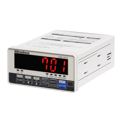
Minebea CSD-709 User manual

DIGITAL PEAK HOLDER
CSD-709
Instruction Manual
EN294-1742E


Introduction
1
Introduction
Thank you for your selecting our CSD-709 digital peak holder. This manual describes installation,
connection, setting, and operating procedures for your equipment. Please read this manual carefully
before using your CSD-709.
Also, be sure to transfer this manual to the final user of the CSD-709. The final user of the equipment
should read the manual and file it carefully.
CAUTION
The contents of this manual are subject to change without prior notice in order to
reflect improvements to the product.
▼ Meanings of the marks and precautions used in this manual
This manual offers precautions you must follow to avoid injuries and accidents, to maintain
measurement accuracy, and to ensure correct settings and operations. The precautions are given
below.
WARNING
Failure to observe the instructions can result in injury or accident. Always observe
the instructions identified by this mark.
CAUTION
Be sure to read the descriptions identified by this mark to maintain the accuracy of
measurements or prevent malfunctions.
POINT
Provides supplementary information with respect to the installation, setting, and operation of the
CSD-709, as well as its connection to other devices. Read the descriptions identified by this
mark whenever necessary.
Indicates where related descriptions can be found.

Introduction
2
In this manual, the headings of sections and paragraphs indicate the accompanying functions used
to set various features of the CSD-709. For example, the heading shown below accompanies
function [CF-07] in order to set an appropriate value for C function CF-07 when it is necessary to set
the excitation voltage.
*****************************************************************************************************************
2.3 Setting the excitation voltage [CF-07]
*****************************************************************************************************************
Furthermore, the default of each function is described on an as-needed basis in this manual. For
example, the default for C function CF-07 used to set the excitation voltage is described as shown
below.
*****************************************************************************************************************
10 VDC
*****************************************************************************************************************
Default

Safety Precautions
3
Safety Precautions
To use the CSD-709 safely, be sure to observe the following precautions.
▼ Precautions
When settings are changed incorrectly during measurement with the CSD-709, correct results
may not be obtained or the equipment may malfunction and cause damage to peripheral
devices.
Do not cause impact to the CSD-709, for example, by striking it against a nearby object.
Otherwise, the components may be damaged or the electrical circuit may fail.
Do not press the front panel of the CSD-709 with excessive force or with the sharp edge of a
screwdriver, for example. Otherwise, panel switches may be damaged or the operability or
environmental worthiness of the CSD-709 may be impaired.
Do not remove the case lid, remove the panel seat, or disassemble the CSD-709, except in
order to replace a fuse. Otherwise, the case or panel seat may be damaged or the operability or
environmental worthiness of the CSD-709 may be impaired.
▼ Compatible standard
The CSD-709 conforms to the following standards:
EN61326-1: 2013
[Electrical equipment for measurement, control, and laboratory use - EMC requirements Part 1:
General requirements]
[Immunity requirements for equipment intended to perform functions in a safety-related system
(functional safety) in industrial locations]
EN61010-1: 2010
[Safety requirements for electrical equipment for measurement, control, and laboratory use -
Part 1: General requirements]
EN50581: 2012
[Technical documentation for the assessment of electrical and electronic products with respect
to the restriction of hazardous substances] (RoHS Directive)
CAUTION
The CSD-709 conforms to EN61326-1 and EN61010-1 when the following
conditions are met.
Shielding
All cables, except for power cables, shall be of the shielded type. For the shielding
method, see related sections.
Grounding
The CSD-709 shall be grounded based on Type D single grounding using a
protective ground connector.

Revision History
4
Revision History
Date Manual No. Revision reason (details)
2017/03 DRW. No. EN294-1742 ROM Ver.1.000
2017/04 DRW. No. EN294-1742A
Due to ECN No.FN17-02059
A.11.3 BCD output (Sync type), A.11.4 BCD outpu
t
(source type)
Change from [~1 000, or 4 000 times/s] [~ 1 000, 2 000,
or 4 000 times/s].
G3. Setting, Function Setting Table
F-33
Change from [~, 2 (5 ms)] to [~, 2 (10 ms), 3 (5 ms), 4
(1.25 ms), 5 (0.5 ms), 6 (0.25 ms), 7 (0.125 ms)].
F-34
Change from [~, 5 (1 000 times/s), 6 (4 000 times/s)] to [~,
5 (1 000 times/s), 6 (2 000 times/s) ,7 (4 000 times/s)]
2017/06 DRW. No. EN294-1742B
Due to ECN No.FN17-02111
7.5. Change [Confirmation with Check mode] to
[Confirmation with Check mode (EzCTS, Version,
Options, Excitation voltage, External control input/output,
Analog output, BCD output, Monitor mode)]
7.5.1. Changing the settings in EzCTS mode
Add [EzCTS is a personal computer application (option).
The function data of CSD-709 can be easily read-out and
written with EzCTS. This software is useful for
maintenance and backup of data.]
A.10. Accessories
Change [CD-ROM(application)] to CD-ROM *
(CSD-709D-01, EzCTS)
Add [* The CD-ROM attached when the optional
additional memory is mounted in the CSD-709 includes
both of the dedicated application CSD-709D-01 and the
EzCTS.]
2018/06 DRW. No. EN294-1742C
Due to ECN No.FN18-02034A
G1 Wiring
・Add the note.
Only BCD-ENABLE (pin number B15) of the source
type becomes effective at the [OPEN].
Use this function after short-circuiting B15 and A1 or B1
when you do not use it.
G4. Timing chart
・Raplace the drawing.
・Correct mis-writing

Revision History
5
Date Manual No. Revision reason (details)
2019/03 DRW. No. EN294-1742D
Due to ECN No.FN19-0159
8-1. Correction
The following statement is added to the note of the
external control input.
・Do not assign the same set value to multiple PIN
numbers.This instrument does not work properly.
2019/07 DRW. No. EN294-1742E
Due to ECN No.FN19-0199
7.7 Printing with serial interface -> Print command through
serial interface.
8.1 External control input signal
Designate print command (only when the serial interface
card is mounted. -> print command (through serial
interface), Print command synchronization mode.
Add the explanation in [POINT] column
・Refer the [10.3 Data format] for Print command
synchronization mode.
Designate print command (only when the serial interface
card is mounted. -> print command (through serial
interface), Print command synchronization mode.
A.4.1 External input signal
Print command (serial interface) -> Print command (serial
interface), Print command synchronization mode
J.4 Calibration based on Modbus
Address -> Data, Data -> Address
K.3 Setting, K4 Checking on Problems
Printing with serial interface -> Print command through
serial interface,
Print signal synchronization→Print command
synchronization.
Function setting table
F-30, F-37 Print signal synchronization -> Print command
synchronization
F-55 4 (Printing with serial interface) -> (Print command
through serial interface)
Due to ECN No.FN19-0446
A.11.10 correct the unit from [bps] to [kbps].

Contents
6
Contents
Introduction ......................................................................................................................................1
Safety Precautions ...........................................................................................................................3
Revision History ...............................................................................................................................4
Contents............................................................................................................................................6
1Overview..................................................................................................................................9
1.1 Checking contents of package ...............................................................................................................9
1.2 Connectable components.......................................................................................................................9
1.3 Features of CSD-709 ...........................................................................................................................10
1.4 Nomenclatures and functions............................................................................................................... 11
1.5 Mode ....................................................................................................................................................13
1.6 Basic key operation ..............................................................................................................................15
1.7 Procedures to prepare for operation of the CSD-709 ...........................................................................16
2Installation and Wiring .........................................................................................................17
2.1 Installation ............................................................................................................................................17
2.2 Wiring ...................................................................................................................................................20
2.3 Setting the excitation voltage ...............................................................................................................29
3Calibration .............................................................................................................................30
3.1 Overview ..............................................................................................................................................30
3.2 Changing the calibration number..........................................................................................................33
3.3 Setting the decimal point display position.............................................................................................35
3.4 Calibration based on actual load ..........................................................................................................36
3.5 Calibration based on input of numerical value......................................................................................40
3.6 Fine adjustment....................................................................................................................................45
3.7 Simplified calibration ............................................................................................................................48
3.8 Verifying the registered calibration data ...............................................................................................52
4Settings Related to Measurement .......................................................................................53
4.1 Overview ..............................................................................................................................................53
4.2 Setting the AD sampling frequency ......................................................................................................54
4.3 Setting the digital filter ..........................................................................................................................56
4.4 Enabling the analog peak detection circuit ...........................................................................................58
5Settings Related to Detection ..............................................................................................60
5.1 Setting the detection conditions............................................................................................................60
5.2 Detection with multimode .....................................................................................................................72
5.3 Detection result judgment and waveform comparison..........................................................................75
6Settings Related to Comparison..........................................................................................81
6.1 Overview ..............................................................................................................................................81
6.2 Setting the comparison value ...............................................................................................................83
6.3 Setting the comparator operating condition..........................................................................................84
6.4 Setting the comparator hysteresis ........................................................................................................86
7Settings Related to Operation .............................................................................................88
7.1 Overview ..............................................................................................................................................88
7.2 Setting the display update frequency ...................................................................................................89
7.3 Lock......................................................................................................................................................90
7.4 Setting the overload display .................................................................................................................92
7.5 Confirmation with Check mode (EzCTS, Version, Options, Excitation voltage, External control
input/output, Analog output, BCD output, Monitor mode) ..................................................................... 93

Contents
7
7.6 Output of CHECK value .......................................................................................................................99
7.7 Setting the F key operation ................................................................................................................100
7.8 Zero set and effective range...............................................................................................................101
7.9 Setting hold targets ............................................................................................................................102
7.10 Initialization of setting ......................................................................................................................... 103
8Settings Related to Output Control ...................................................................................104
8.1 External control input signal ...............................................................................................................104
8.2 External control output signal .............................................................................................................107
9Troubleshooting.................................................................................................................. 110
9.1 Error code list ..................................................................................................................................... 110
9.2 Troubleshooting.................................................................................................................................. 112
9.3 Replacing the fuse.............................................................................................................................. 114
10 Communications via USB .................................................................................................. 115
10.1 Communication specifications............................................................................................................ 115
10.2 Setting the USB interface ................................................................................................................... 116
10.3 Data format ........................................................................................................................................120
10.4 Remote calibration via USB ...............................................................................................................128
ASpecifications of CSD-709 .................................................................................................132
A.1 Analog Specifications .........................................................................................................................132
A.2 Digital Specifications ..........................................................................................................................133
A.3 Functions of Front Panel Sheet Key Switches ...................................................................................133
A.4 External Control Function...................................................................................................................134
A.5 Comparator Function..........................................................................................................................135
A.6 Function ............................................................................................................................................. 136
A.7
USB Interface (for connection with EzCTS and specialized application)
....................................................................137
A.8 General Specifications .......................................................................................................................137
A.9 Standard Shipment Specifications......................................................................................................137
A.10 Accessories........................................................................................................................................138
A.11 Option.................................................................................................................................................139
BWarranty ..............................................................................................................................143
B.1 Warranty.............................................................................................................................................143
B.2 Repairs...............................................................................................................................................143
B.3 Component Service Lives ..................................................................................................................143
CCharacter Display Pattern ..................................................................................................144
DDetection Operation and Section ......................................................................................145
D.1 Detection operation ............................................................................................................................145
D.2 Detection section................................................................................................................................ 154
EVoltage Output Card CSD-709-29 ......................................................................................157
E.1 Wiring .................................................................................................................................................157
E.2 Setting ................................................................................................................................................158
E.3 Calibration ..........................................................................................................................................160
E.4 Adjustment .........................................................................................................................................162
E.5 Output Operation in Hold Mode.......................................................................................................... 164
E.6 Checking on Problems .......................................................................................................................164
FCurrent Output Card CSD-709-07 ......................................................................................165
F.1 Wiring ................................................................................................................................................. 165
F.2 Setting ................................................................................................................................................ 166
F.3 Calibration ..........................................................................................................................................168
F.4 Adjustment .........................................................................................................................................170
F.5 Output Operation in Hold Mode..........................................................................................................172
F.6 Checking on Problems .......................................................................................................................172

Contents
8
GBCD Card CSD-709-15/CSD-709-16 ...................................................................................173
G.1 Wiring .................................................................................................................................................173
G.2 Output specifications ..........................................................................................................................175
G.3 Setting ................................................................................................................................................175
G.4 Timing chart........................................................................................................................................ 176
G.5 Output Operation in Hold Mode.......................................................................................................... 177
G.6 Checking on Problems .......................................................................................................................177
HRS-232C Card CSD-709-74 .................................................................................................178
H.1 Wiring .................................................................................................................................................178
H.2 Communication specifications............................................................................................................179
H.3 Setting ................................................................................................................................................179
H.4 Checking on Problems .......................................................................................................................180
IRS-422/485 Card CSD-709-76.............................................................................................181
I.1 Connection .........................................................................................................................................181
I.2 Communication specifications............................................................................................................182
I.3 Setting ................................................................................................................................................183
I.4 Checking on Problems .......................................................................................................................184
J
Communications Based on Modbus Protocol
..............................................................................185
J.1 Communication specifications............................................................................................................185
J.2 Setting ................................................................................................................................................186
J.3 Modbus function forma.......................................................................................................................187
J.4 Calibration based on Modbus.............................................................................................................194
KSerial Interface Card CSD-709-77 ......................................................................................197
K.1 Connection .........................................................................................................................................197
K.2 Communication specifications............................................................................................................198
K.3 Setting ................................................................................................................................................198
K.4 Checking on Problems .......................................................................................................................198
L
External Control Voltage Input Type Circuit CSD-709-44
..............................................................................199
L.1 Connection .........................................................................................................................................199
MPower Supply Voltage CSD-709-67....................................................................................200
M.1 Connection .........................................................................................................................................200
Function Setting Table .................................................................................................................201

1 Overview
9
1 Overview
1.1 Checking contents of package
Before using the CSD-709, be sure to check if the package contains all the items listed below.
CSD-709: 1
Startup Guide (in Japanese and English): 1 set each
Midget fuse (2.5 A): 1
Unit seal: 1
External control input/output connector: 1
Strain-gage-based transducer connector: 1
CAUTION
The following components are contained in the package when options are mounted
to the CSD-709.
Voltage output plug (component for CSD-709-29): 1
Current output plug (component for CSD-709-07): 1
BCD output plug (component for CSD-709-15/CSD-709-16): 1
RS-232C plug (component for CSD-709-74): 1
RS-422/485 plug (component for CSD-709-76): 1
Serial interface plug (component for CSD-709-77): 1
CC-Link plug (component for CSD-709-73): 1
Application CD-ROM (medium for CSD-709-91): 1
USB cable (component for CSD-709-91): 1
1.2 Connectable components
A strain-gage-based transducer, such as a load cell or pressure sensor, can be connected to the
CSD-709. A PC and printer can also be connected. Shown below are the components that can be
connected to the CSD-709.
Strain-gage-
based transducer
RS-232C
RS-422/485
BCD
CC-Link
SI/F
USB
Measuring devices such as a
voltmeter, ammeter, or data
logger
External control devices such as
a PLC
Printer and display
PC (for additional memory or
PC application)
Voltage/current output

1 Overview
10
1.3 Features of CSD-709
1.3.1 Basic functions
The CSD-709 supports the following basic functions.
The CSD-709 captures the sharp peak load more accurately by means of high-speed AD
sampling of up to 4 000 times/s, an analog low-pass filter, a digital low-pass filter, and
moving-average processing. It also supports an analog peak hold function that enables more
rapid peak capturing regardless of sampling rate.
The CSD-709 supports a simplified calibration function that starts the calibration process by
simply holding down a key. Calibration based on communication through various interfaces is
also available.
In the pre-work check, you can use preset check values to easily verify that the correct
calibration status is maintained.
The load currently applied to the strain-gage-based transducer, such as the load cell, is
displayed in mV/V, allowing you to separate abnormal values and unstable measured values.
Tracks and peaks can be output in analog form. The hold target can be flexibly selected from
displayed values and comparative outputs.
Up to four different types of calibration data or comparator settings are memorized so that you
can select the desired value by means of key operation or external control input.
You can select the peak detection mode from 36 modes configured through a combination of
nine hold modes (peak hold, bottom hold, peak-bottom hold, peak-to-peak hold, maximum hold,
minimum hold, maximum-minimum difference hold, average hold, and four inflection point holds)
and four section modes (entire section, specified section, time-specified section, and automatic
start time-specified section).
1.3.2 Addition of functions using options
The following additional functions become available through mounting options.
Current and voltage outputs synchronizing with high-speed AD sampling
Sink-type and source-type BCD outputs
Readout of loads and confirmation/change of settings by means of RS-232C interface
Readout of loads and confirmation/change of settings by means of RS-422/485 interface
Readout of loads by means of serial interface (S-I/F)
Power supply voltage in DC
External control input in voltage
Readout of loads and confirmation/change of settings by means of CC-Link interface
Utilization of PC applications through the addition of memory

1 Overview
11
1.4 Nomenclatures and functions
1.4.1 Front panel
1. Load window
Indicates the value currently measured in Measurement mode. Also indicates
the settings in any mode other than Measurement mode, such as Function
mode.
2. Status
window
Indicates the current condition by turning on the associated LED.
SEL1, SEL2 Either LED is turned on depending on the calibration
number selected.
CHECK This LED is turned on while the check value is being
output.
HOLD This LED is turned on in hold mode.
PEAK This LED is turned on during detection of a peak.
MEAS. This LED is turned on during detection of a peak in a
section other than reset section.
END This LED is turned on during detection of a peak in the
hold mode.
LOCK This LED is turned on in the key lock mode.
3. Judgment
window
Indicates the condition of the selected external control output by turning on the
associated LED.
4. Key
Inputs commands necessary for settings and operations.
Selects any mode other than Measurement mode, such as
Function mode. Holding this key down for at least two
seconds triggers simplified numerical value input based
calibration.
Allows you to move to the next upper digit in the target
setting. Holding this key down for at least two seconds
triggers simplified zero calibration.
Increases the numerical value of the target setting by one.
Holding this key down for at least two seconds triggers
simplified span calibration.
Selects the track or various peak detections.
Resets the peak. Also outputs the CHECK value.
Executes the F key operation already set. Also registers the
setting.

1 Overview
12
1.4.2 Rear panel
1. Protective ground connector The grounding cable is plugged in here.
2. Power supply connector board The power cable is plugged in here.
3. Connectors for options The cable suitable for the option mounted is plugged in
here.
4. External control input/output
connector
The external control input/output connector is plugged
in here.
5. Strain-gage-based transducer
connector
The signal cable from the strain-gage-based
transducer or the strain-gage-based transducer
connector to which the monitor output signal cable is
connected is plugged in here.
6. USB interface connector The USB cable is plugged in here.

1 Overview
13
1.5 Mode
The CSD-709 supports the following measurement and operating modes.
Measurement mode: You can display the value currently measured. Measurement mode is
further divided into two modes: Track mode and Peak mode. In Track mode, the value, which is
input from the measuring unit and changes with the elapse of time, is displayed in the load
window. In Peak mode, the maximum and minimum measurements are detected and held.
Function mode: You can set the functions prefixed with [F-], including the function related to the
number of AD sampling times and the measurement of the digital filter, the function related to
comparisons (e.g., operation of the comparator), and the function related to the operation of the
key lock and hold target, and check these settings.
C function mode: You can set the functions prefixed with [CF-], including the selection of
calibration number, decimal point display position, and current calibration data, and check these
settings.
P function mode: You can set the peak hold related functions prefixed with [PF-], including
determination of the detecting section and execution of detection, and check these settings.
CAL selection mode: You can select CCAL mode used for calibration, CADJ mode used for fine
adjustment of calibration results, and VCAL mode and VADJ mode used for calibration and
adjustment of optional current output and voltage output cards.
Check mode: You can check CSD-709's ROM version, mounted options, external control
operations, and the like.
COMP setting mode: You can set comparison values and check comparator settings.
Measurement mode
Function mode
C function mode
P function mode
CAL selection mode
CCAL mode
CADJ mode
VCAL mode
VADJ mode
Check mode
COMP setting mode

1 Overview
14
The mode in which multiple detection operations, such as peak detection, maximum detection, and
inflection point detection, are combined to obtain the results from the load changing with the elapse
of time is called [multimode] and distinguished from operations based on a single detecting
sequence ([single mode]).

1 Overview
15
1.6 Basic key operation
To toggle between Measurement mode and any other mode, use the key. To move to any of
COMP setting modes from the Function mode, press the or key to change the display,
then press the key. To return to Measurement mode from any other mode, press the key
several times.
In Function, C function, and P function modes, respectively, the following numerical values prefixed
with the codes shown below are displayed.
Mode Prefix Representation in this manual
Function mode F-xx [F-xx]
C function mode CF-xx [CF-xx]
P function mode PF-xx [PF-xx]
Function mode
CAL selection mode
Check mode
COMP setting mode
C function mode
P function mode
Measurement mode

1 Overview
16
In these modes, the and keys execute digit movement and value change, respectively.
Key Function
Allows you to move to the adjacent digit.
Changes numerical values 0 to 9.
For example, to change the display from to , conduct the following steps.
1. Press key to flash [2].
2. Press key to change [2] to [4].
3. Press key to flash [1].
4. Press key to change [1] to [3].
To input the calibration data, use and as well.
1.7 Procedures to prepare for operation of the CSD-709
Before using the CSD-709, conduct the following setting sequence.
1. Install the CSD-709. (See Section 2.1, "Installation".)
2. Connect cables to the CSD-709. (See Section 2.2, "Wiring".)
3. Calibrate the CSD-709. (See Section 3, "Calibration".)
4. Set the CSD-709 according to the intended application. (See Sections 4, "Settings Related to
Measurement" to 7 "Settings Related to Operation".)
5. Start the operation.

2 Installation and Wiring
17
2 Installation and Wiring
2.1 Installation
2.1.1
Precautions
Use the CSD-709 within the temperature and humidity ranges specified below.
Ambient temperature -10°C ~ 50°C
Ambient humidity 85 %RH, max (No condensation is permitted.)
WARNING
Do not install the CSD-709 in any of the locations listed below.
Locations exposed to direct sunlight or high temperatures
Damp locations
Locations exposed to vibrations or impact
Locations exposed to lots of dust or fine particles
Environments containing corrosive gases or salt
Locations subject to sudden temperature or humidity fluctuations
Close to equipment that generates magnetic or electromagnetic radiation
Locations subject to the effects of radiation and radioactive materials
Locations such as laboratories where chemical changes may occur
2.1.2
Installing the CSD-709
This section describes the external dimensions of the CSD-709 and the appropriate installation
procedures. Shown below are its external dimensions and panel cut dimensions.
External control input/output connector plugged in:
Strain-gage-based transducer connector plugged in:
Panel cut dimensions
92
45
96
48
1411110
10 111 (46)

2 Installation and Wiring
18
Described below are the installation procedures for the CSD-709.
1. Drill holes in the panel according to the panel cut dimensions.
2. Remove the two screws (A) from the rear panel and detach the two panel fittings (B) from both
side panels.
3. Mount the CSD-709 from the front of the panel.
Other manuals for CSD-709
1
Table of contents
Other Minebea Measuring Instrument manuals

Minebea
Minebea CSD-401 User manual

Minebea
Minebea CSD-904-EX User manual

Minebea
Minebea TMD-100 User manual

Minebea
Minebea MIS-202-PT User manual

Minebea
Minebea CSD-814B User manual

Minebea
Minebea CSD-892B-07-25 User manual

Minebea
Minebea CSD-701C User manual

Minebea
Minebea CSD-892B-74 User manual

Minebea
Minebea MIS-202-PT User manual

Minebea
Minebea CSD-801 User manual