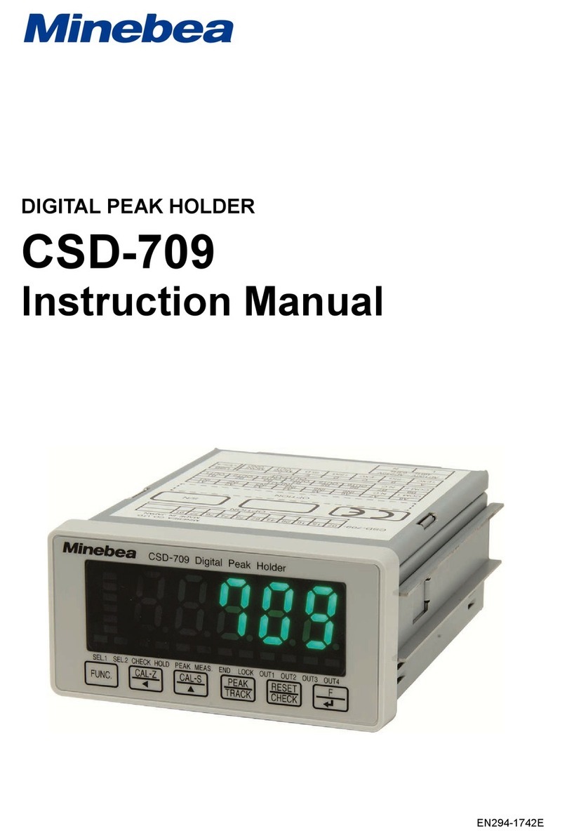
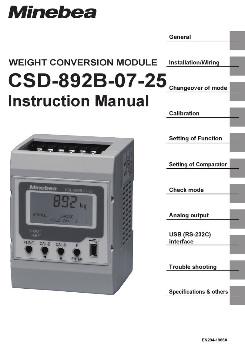
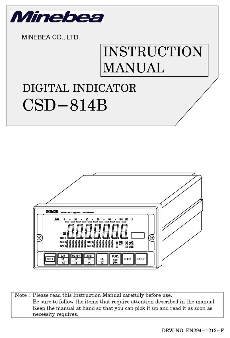
Minebea CSD-801 User manual

Artisan Technology Group is your source for quality
new and certied-used/pre-owned equipment
• FAST SHIPPING AND
DELIVERY
• TENS OF THOUSANDS OF
IN-STOCK ITEMS
• EQUIPMENT DEMOS
• HUNDREDS OF
MANUFACTURERS
SUPPORTED
• LEASING/MONTHLY
RENTALS
• ITAR CERTIFIED
SECURE ASSET SOLUTIONS
SERVICE CENTER REPAIRS
Experienced engineers and technicians on staff
at our full-service, in-house repair center
WE BUY USED EQUIPMENT
Sell your excess, underutilized, and idle used equipment
We also offer credit for buy-backs and trade-ins
www.artisantg.com/WeBuyEquipment
REMOTE INSPECTION
Remotely inspect equipment before purchasing with
our interactive website at www.instraview.com
LOOKING FOR MORE INFORMATION?
Visit us on the web at www.artisantg.com for more
information on price quotations, drivers, technical
specications, manuals, and documentation
Contact us: (888) 88-SOURCE | sales@artisantg.com | www.artisantg.com
SM
View
Instra

INSTRUCTION MANUAL
FOR
CSD-801 DIGITAL INDICATOR
MINEBEA CO., LTD.
SHINKOH COMMUNICATION DIVISION
DRW.NO. 294-1011-A
Artisan Technology Group - Quality Instrumentation ... Guaranteed | (888) 88-SOURCE | www.artisantg.com

Artisan Technology Group - Quality Instrumentation ... Guaranteed | (888) 88-SOURCE | www.artisantg.com

CONTENTS
§1.
§2.
§3.
OUTLINE
FEATURES
NAME OF EACH PART
Page
1
1
2
3-1 Front panel 2
3-2 Rear panel 3
§4. INSTALLATION 4
§5. CONNECTION METHOD 5
5-1 Terminal board for power and transducer 5
5-2 Terminal board for digital control 5
5-3 BCD-OUT connector 6
5-4 Precautions for connection 8
§6. HANDLING PROCEDURE 10
6-1 Connection 11
6-2 Power ON 11
6-3 Actual load calibration-I 12
6-4 Actual load calibration-II 16
6-5 Actual load calibration-III 17
6-6 Electric calibration-I 19
6-7 Electric calibration-II 20
6-8 Registration of each function by SET MODE 21
6-9 Start of measurement 21
CSD-801 DIGITAL INDICATOR
Artisan Technology Group - Quality Instrumentation ... Guaranteed | (888) 88-SOURCE | www.artisantg.com

§7. FUNCTION IN MEASUREMENT MODE 22
7-1 Zero set function 22
7-2 AUTO ZERO, AUTO ZERO OFF function 23
7-3 Comparative setting function (Comparator) 25
7-4 CENTER ZERO function 27
§8. FUNCTION BY SET MODE (INITIAL SETTING FUNCTION) 28
8-i Required switch for SET MODE 29
8-2 ZERO TRACKING 30
8-3 Minimum effective digit setting function 34
8-4 Multiplication function 38
8-5 Pre-set cancellation function 40
8-6 Comparative setting condition
changeover function 43
8-7 Judgment function 46
8-8 Dummy 0 indication 49
8-9 Decimal point indication 51
8-10. Sign inversion function 53
8-11 Sign transfer function 55
8-12 BCD-OUT true conversion 57
8-13 Unit indication changeover 58
8-14 Manual Z/S function 59
8-15 Back-up Data Clear 60
§9. SELF-CHECK FUNCTION 61
§10. ERROR INDICATION 61
§11. SET MODE SETTING VALUE TABLE 65
Artisan Technology Group - Quality Instrumentation ... Guaranteed | (888) 88-SOURCE | www.artisantg.com

§12. ANALOG ADJUSTMENT 67
12-1 Standard parts adjustment 67
12-2 Layout of adjustment parts 68
12-3 Adjustment of bridge voltage 69
12-4 GAIN adjustment 69
12-5 Change of CHECK value 71
12-6 Change of TARE cancel value 73
§13. SPECIFICATION 75
13-1 General specification 75
13-2 Block Diagram 78
13-3 Appearance Drawing 80
§14. ACCESSORIES 81
Artisan Technology Group - Quality Instrumentation ... Guaranteed | (888) 88-SOURCE | www.artisantg.com

Artisan Technology Group - Quality Instrumentation ... Guaranteed | (888) 88-SOURCE | www.artisantg.com

§1. OUTLINE
The equipment is CPU mounted digital indicator for
instrumentation.
§2. FEATURES
oRemote setting function is provided to the converter
(transducer) power, and the error from cable length
will be cancelled.
oFlying capacitor is adopted at signal amplifier input
step. In common mode noise reduction ratio is set at
120dB.
oDrift at the signal amplifier is reduced as much as
possible by chopper amplifier.
oMaximum indication is 9999, with multi (multiplying)
function and, at dumy (-)0, indication up to (+)199980
is possible.
oProvided with BCD parallel-out output (open collector),
which can simultaneously output the total load and
net load.
oSetter is provided with 5-digits 2-steps digital switch,
as well as pre-set cancellation and judgment functions.
It can also be connected to MINEBEA digital setter
CSD-551B by using BCD parallel out connector.
oBy its zero tracking function, secular change in zero-
point of the converter and the like will be cancelled.
1/81
Artisan Technology Group - Quality Instrumentation ... Guaranteed | (888) 88-SOURCE | www.artisantg.com

§3 -
IIii
9
M--sao 11 G;51 Ital IF meettnlO
Ci
11
• WO I117 tali 0 rt 41
0CO igi IN Li
L'o
o�sEi
A*2
voce
"I r
0
eI
0s]
fillrillini
woo
1E1111
mum
11,lArE ZERO GAIN SPAN C/S
91F35? , NINTH
15-1/2 digits 7 segments LED 12 Zero trimmer
2C/Z LED 13 GAIN rotary switch
3High LED 14 Span trimmer
4Low LED 15 C/S rotary switch
5High setting digi-switch 16 Set mode switch
6Low setting digi-switch 17 Check switch (with LED)
7' V-out zero adjust trimmer 18 A/Z off switch (with LED)
8 V-out span adjust trimmer 19 A/Z switch
9I-out zero adjust trimmer 20 Z/S switch (with LED)
10 I-out span adjust trimmer 21 Unit select LED
11 TARE rotary switch
NAME OF EACH PART
3-I Front panel
2/81
Artisan Technology Group - Quality Instrumentation ... Guaranteed | (888) 88-SOURCE | www.artisantg.com

§4. INSTALLATION
For the safe and complete operation of the instrument,
it is important that equipment is installed properly
in a suitable location. Ideally, a dry room with
uniform temperature environment will be the most
suitable location.
(1) When installing, select a location where mechanical
vibration and corrosive gas are minimal, with small
temperature change near the normal temperature.
(temperature compensated range i 0 % 50°C)
(2) The equipment is panel-mount type. When mounting to
apanel, prepare square holes at designated positions.
(Refer to panel outline drawing and panel cut
dimensions.)
4/81
Artisan Technology Group - Quality Instrumentation ... Guaranteed | (888) 88-SOURCE | www.artisantg.com

Z/S external contact--
I0 Cil
A/2 external contact —I 0-Zt
IN
A/Z OFF external contact --1-- C
CHECK external
1-3
Red
D—
m
3
Blue
White
5
H.
tr
0
o
m
Green
I
crl
94rt
o
Shield
(r, tcs
•C)
0Ground earth _t-\
II
1--•
IQ
oz
ct
AC power input
L°
contact ----
-0 0
00-- 11
-r-
rn
7t
0
A
11-0
<
HIGH contact output
7- 0
Twist regulation --
r-
0n
LOW contact output //
Twist regulation -71:0
OK contact output
Twist regulation rrIM
ERROR contact output
Twist regulation X
0
0
0
0
0
0
0
0
O
0
ulLoad cell etc.
0
0
K
hLoad cell etc. Red
0
AC power input
01 co)
Lri
I— •
o
o
Z
5
H-
PJ H
0
tr Z
0
13) X
tzi
H't 0
0IV
ro
tD
rt
H
I1)
UI
0
Artisan Technology Group - Quality Instrumentation ... Guaranteed | (888) 88-SOURCE | www.artisantg.com

°Input circuit (Z/S,A/Z,OFF,CHECK)
25 24 23 221 21120 19 1 18 [17 16 15 14 13 12 11 10 9 8 [ 716 15 43 2 1 1
Roev
ton
ft
HP
o
4r‘,"4
r
P
T
0
I
181.4 2184 2 181 41 2 11 8 4 2 1 1
1041 103
14 1 N
103
N
101
N
100
N
50 49 48 47 46 49 44 43 42 41 40 39 38 37 36) 35 1 34 33 1 32 31 30 29 28 27 1 26
C
0
M
oH
I.
.
N
p
C
N
P
C
T1
0
v
f
N
-4
I8421841 2 1 1 81 4 2 1 8 4 2 1 1
10'
i
101
T
101
i
10'
f
10°
T
POL Lat + data and H at - data when ERROR Error
polarity is high true. COM Signal ground
OVF Data over (overflow) XXX-N Net load
PC Print command -(during data conversion) XXX-T Total load
HOLD Data hold (fixed low true input)
Photocoupler z/s
n/z
A/'7,10fF
IIECK
OM
5-3 BCD-OUT connector
°Pin arrangement
°Output circuit (HIGH,LOW,OK,ERROR)
aContact AC250V DC30V 0.
Naristor
(Note) In case of TTL level output (option), the true will be reverse.
°.Input circuit (HOLD) °Output circuit (Others)
HOLD
6/81
BCD— OUT
COM
Artisan Technology Group - Quality Instrumentation ... Guaranteed | (888) 88-SOURCE | www.artisantg.com

Timing Chart (When data command is high true output)
DATA
ML
P. C.
HOLD
DATA
POL
P. C .
DATA
POL
P. C .
O. V. F.
DATA
POL
P. C .
4RMDR
°Normal
0,2mS 270m8
°Hold signal input
60••••••••=.•••
°Data over (overflow)
°Error
7/81
ML
L
H
Artisan Technology Group - Quality Instrumentation ... Guaranteed | (888) 88-SOURCE | www.artisantg.com

5-4 Precautions for connection
(1) Wiring of sensor input (A, B, C, D, E, F, G)
For connection, use MINEBEA shild cable SKB-4012
(4-wires) or SKB-4011(6-wires). When using 6-wires
cable, maximum length of the cable should be up to
200m.
It is essential that this wiring is separated from
the wirings for power circuit and for control contact
output circuit. In any case, it must not be placed
near a cable with big current flow such as power
cable. Therefore, in case of conduit wiring,
aseparate conduit from that of power circuit and
control contact output circuit should be used.
(2) Wiring of "Out" circuit (V-Out, I-Out)
Use 2-core shilding wire. The load shall be more
than 2 k0 at V-Out and less than 500 0 at I-Out
(option). Wiring should be as short as possible,
and as in (1) above, should be wired away from power
cable. or the like.
(3) Wiring of control signal input circuit (Z/S, A/Z, OFF,
CHECK)
In order to avoid the reception of external noise,
the input circuit is received internally at the
photocoupler, but the wiring should be short and
should be away from power cable or the like.
8/81
Artisan Technology Group - Quality Instrumentation ... Guaranteed | (888) 88-SOURCE | www.artisantg.com

(4) Wiring of control contact output circuit (HIGH, LOW,
OK, ERROR)
Wiring cable should be determined according to the
applied voltage, current and so forth. Normally,
the cable does not require shielding.
(5) Wiring of GND (earth) circuit
GND terminal is linked with the amplifier body.
From this terminal, pull out the earth wire and,
preferably solder to copper plate or copper rod and
bury in wet ground.
Please note that GND terminal and analog common
(V-Out-terminal etc.) are not common, so make sure
it will not short-circuit.
(6) Wiring of power circuit
"AC" terminal is a connecting terminal for alternate
current power circuit.
"AC" voltage is standard "100V", but if the equipment
is manufactured in specification other than "100V"
according to the customer's requirements, such voltage
value will be entered. Therefore, make sure that the
designated voltage is supplied at all times.
If the voltage supplied is below the rating, the
instrument will not operate, or if operated, its
performance cannot be guaranteed. If excessive
voltage is supplied, the fuse will cause the breaking
of wire, or, there is a danger of internal power
transformer being burned.
9/81
Artisan Technology Group - Quality Instrumentation ... Guaranteed | (888) 88-SOURCE | www.artisantg.com

§6. HANDLING PROCEDURE
In order to utilize the various functions of CSD-801 effectively, adjustments shall be made
according to the following procedure.
In case of changing our standard adjusted product
to the customer's specification or changing the
specification of previously adjusted product.
In case the product has been shipped from
our factory, with adjustment required by
the customer's specification already completed.
Using digital output only Combined use of
analog output
Using digital output
only
Combined use of
analog output
6-1
(Connection)
6-2
(Power on)
6-3
(Actual load
calibration I)
4,
6 -B
(Function' registration`
by set mode)
6-9
(Start measurement)
Basically, adjustment
in our factory will be
required.
Please contact our
sales representative.
6-1
(Connection)
6-2
(Power on)
6-4 6-6
(Actual load
calibration II•
Electric
calibration I)
6-8
(Function registration
by set mode)
4.
6-9
(Start measurement)
6-1
(Connection)
6-2
(Power on)
6-5 6 -7
(Actual load
calibration III.
Electric
calibration II)
6-8
(Function registration
by set mode)
6-9
(Start measurement)
Artisan Technology Group - Quality Instrumentation ... Guaranteed | (888) 88-SOURCE | www.artisantg.com

6-1 Connection
Connect the transducer and the body (CSD-801) according
to Section 5.
When using 4-wires cable (equivalent to our SKB-4012)
for wiring the equipment to the transducer, use the
attached short cable (one each of red and white) and
shorten between A-F and C-G of the terminal board for
transducer, located on the back panel of the equipment.
6-2 Power ON
Check the voltage and current and supply the power.
(standard AC100V)
Confirm the self-diagnosis indication by the equipment.
The indications are as follows.
1) E- 0 :Internal memory will be checked. If there is
an error, a number will be indicated in the ❑.
(For details, refer to Section 10.)
2) 0. 0 :Shows the version of the program. In case of
malfunction, inform this number.
3) :Indications will increment from the right end,
and finally all LED will flash.
4) :With the completion of the above, measuring
mode will start.
Also confirm that the condition of each LED
on the front panel are
Indication data
Lz/s LED
[A/z OFF.
'CHECK
as follows.
XXXX (some value)
OFF
LED ON
LED OFF
Artisan Technology Group - Quality Instrumentation ... Guaranteed | (888) 88-SOURCE | www.artisantg.com

6-3 Actual load calibration-I (for changing specification,
no analog output)
(1) Maintain the condition with initial load on transducer.
(2) Adjust the TARE rotary switch (coarse adjustment) and
ZERO trimmer (fine adjustment) of the equipment, and
confirm that the indication will be 0 (zero).
(3) Apply maximum load on the transducer.
(4) What is the maximum indication required under the
condition of (3) above.
1) less than 999 4- to (5)
2) less than 1999 to (6)
3) less than 4999 to (7)
4) less than 9999 4- to (8)
5) more than 10000 to (9)
(5) Multiply the required indication by 10 times (x 10)
Eg,) If the maximum indication is 800, then
800 x 10 = P1500I
To obtain the calculated value, adjust the 'GAIN'
rotary switch and ISPANI trimmer on the front panel
with the attached micro-driver.
If the adjustment cannot be made, change the bridge
voltage by referring to 12-3 in page 69, and repeat
the same adjustment.
If the adjustment still cannot be made, proceed to (6).
12/81
Artisan Technology Group - Quality Instrumentation ... Guaranteed | (888) 88-SOURCE | www.artisantg.com

If the adjustment is completed, set mode (refer to
Section 8) will start, and by utilizing the minimum
effective digit setting function (Section 8-3, page 34)
cut the 108 digit.
After completion, pass through the set mode and proceed
to (10).
(6) Multiply the required indication by 5 times (x 5)
Eg.) If the maximum indication is 1500, then
1500 x 5 = 17500 1
To obtain the calculated value, adjust the IGAIN1
rotary switch and SPAN trimmer on the front panel
with the attached micro-driver.
If the adjustment cannot be made, change the bridge
voltage by referring to 12-3 in page 69, and repeat
the same adjustment.
If the adjustment still cannot be made, proceed to (7).
If the adjustment is completed, set mode (refer to
Section 8) will start, and by utilizing the multipli-
cation function (Section 8-4, page 38), set the
indication data at 1/5.
After completion, pass through the set mode and
proceed to (10).
(7) Multiply the required indication by 2 times (x 2)
Eg.) If the maximum indication is 3000, then
3000 x 2 = 60001
To obtain the calculated value, adjust the
rotary switch and (SPAN
!GAIN]
trimmer on the front panel
with the attached micro-driver.
13/81
Artisan Technology Group - Quality Instrumentation ... Guaranteed | (888) 88-SOURCE | www.artisantg.com

If the adjustment cannot be made, change the bridge
voltage by referring to 12-3 in page 69, and repeat
the same adjustment.
If the adjustment still cannot be made, proceed to (8).
If the adjustment is completed, set mode (refer to
Section 8) will start, and by utilizing the multipli-
cation function (Section 8-4, page 38), set the
indication data at 1/2.
After completion, pass through the set mode and proceed
to (10).
(8) To obtain the required indication value, adjust the
rotary switch and SPAN trimmer on the front
GAIN
panel with the attached micro-driver.
If the adjustment cannot be made, change
voltage by referring to 12-3 in page 69,
the same adjustment.
If the adjustment still cannot be made, it
that it is out of the specification of the
Please contact our sales representative.
If the adjustment is completed, proceed to
the bridge
and repeat
is possible
equipment.
(10) .
(9) Multiply the required indication by 1/2 time (x 1/2)
Eg.) If the maximum indication is 16000, then
16000 x 1/2 = 8000
To obtain the calculated value, adjust the GAIN
rotary switch and (SPAN trimmer on the front panel
with the attached micro-driver.
If the adjustment cannot be made, change the bridge
voltage by referring to 12-3 in page 69, and repeat
the same adjustment.
14/81
Artisan Technology Group - Quality Instrumentation ... Guaranteed | (888) 88-SOURCE | www.artisantg.com
Table of contents
Other Minebea Measuring Instrument manuals
Minebea
Minebea MIS-202-PT User manual
Minebea
Minebea CSD-814B User manual

Minebea
Minebea MIS-202-PT User manual

Minebea
Minebea CSD-701C User manual

Minebea
Minebea CSD-891B User manual

Minebea
Minebea CSD-401 User manual

Minebea
Minebea CSD-892B-07-25 User manual

Minebea
Minebea CSD-904-EX User manual

Minebea
Minebea CSD-903-73 User manual

Minebea
Minebea CSD-892B-74 User manual
Popular Measuring Instrument manuals by other brands

GESTRA
GESTRA VK 14 Original Installation Instructions

Xylem
Xylem wtw pHotoFlex pH quick start guide

Seres OL
Seres OL TOC User and maintenance manual

Keysight Technologies
Keysight Technologies S9106AC-2IF Startup guide

Sensus
Sensus PulseRF-Mei MS 2820 installation manual

Hioki
Hioki MR8880-20 quick start guide