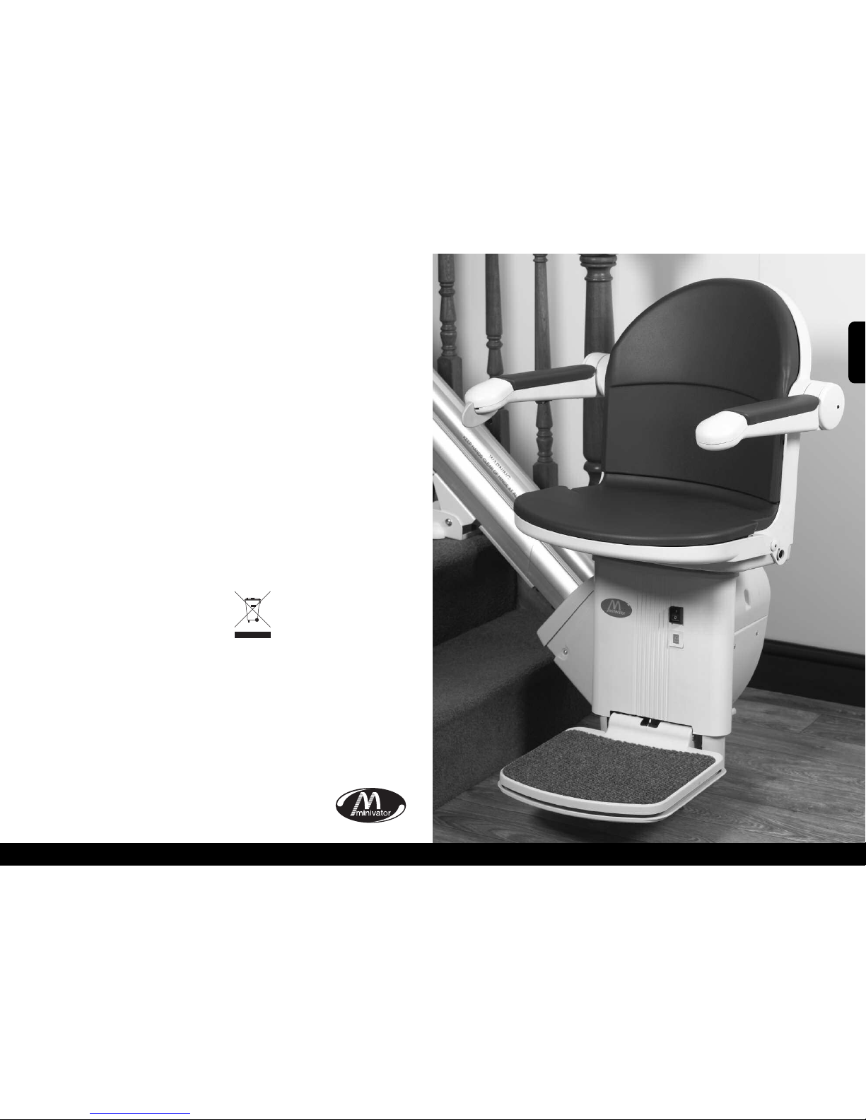
Operating your Minivator 1000
7
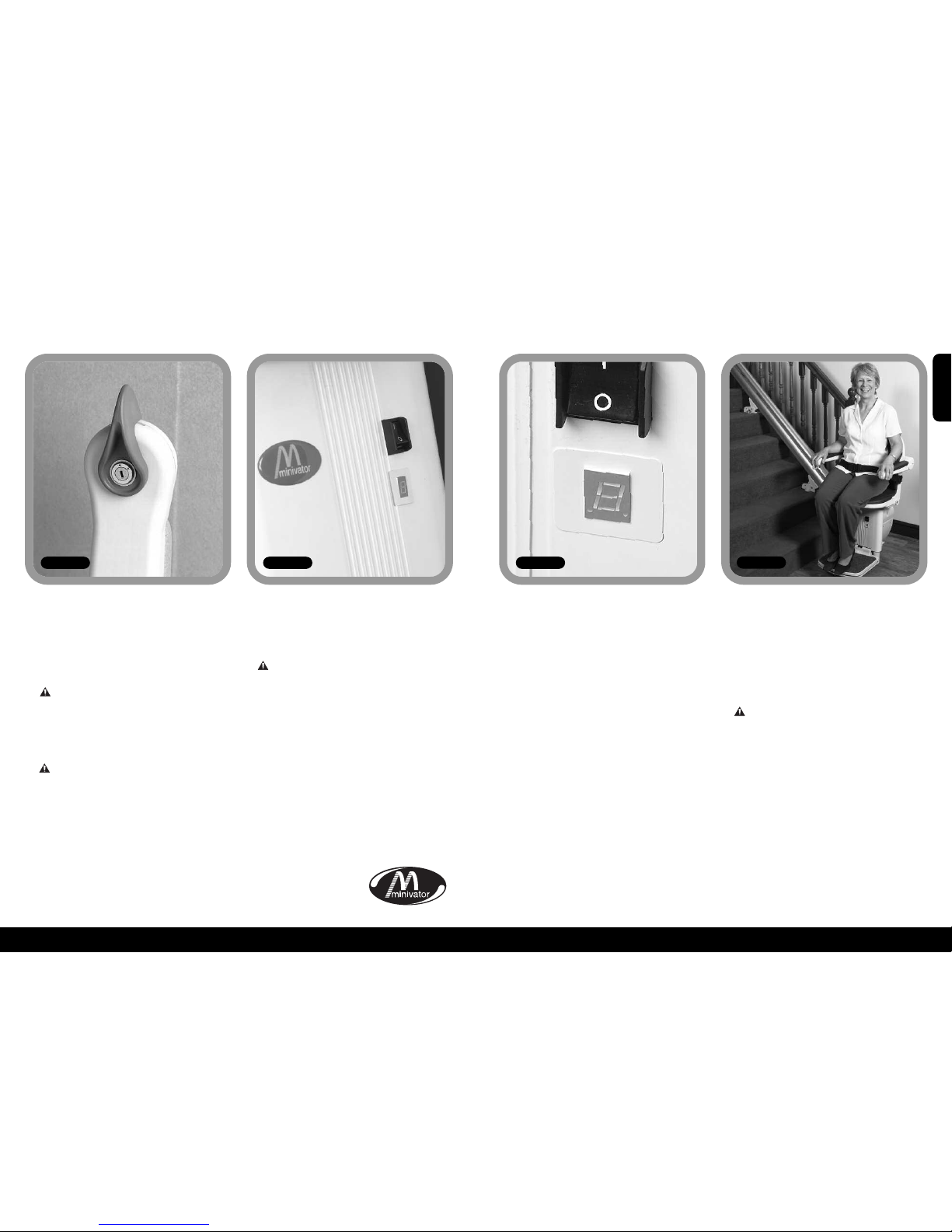
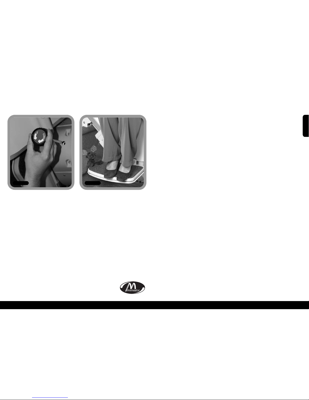
Operating the swivel
8
Figure 10
Aswivel seat is provided to enable you to
mount/dismount the seat moreeasily at
the top of the stairs by swivelling you on
to the landing.
To operate the seat swivel, wait until
the stairlift has stopped.
To swivel the seat hold either (there is one
both sides of the seat) swivel lever down
or pull it up. This will release the seat lock
and allow you to move the seat round by
pushing away from the footplate. When
the seat reaches 90 degrees it will lock in
position.
You should not attempt to leave the seat
until it has firmly ‘clicked’ into its locked
position.
To swivel in the opposite direction follow
the same procedure, but push away from
the landing.
Power operated swivel (optional)
If your stairlift is fitted with an optional
power operated swivel there will be no
swivel levers fitted. In order to swivel the
seat hold the operating toggle in the up
direction. When the stairlift reaches the
top of the stairs continue to hold the
operating toggle in the up direction.
The stairlift will beep three times and
then the seat will swivel. When the seat
is fully swivelled to 90 degrees the seat
will stop.
You should not attempt to leave the seat
until it is fully rotated.
To swivel in the opposite direction follow
the same procedure in reverse. Push the
operating lever in the down direction. The
seat will beep three times and then after a
shortpause it will rotate to the driving
position. Continue to hold the operating
lever in the down direction. The stairlift
will then again beep three times before
beginning its descent.
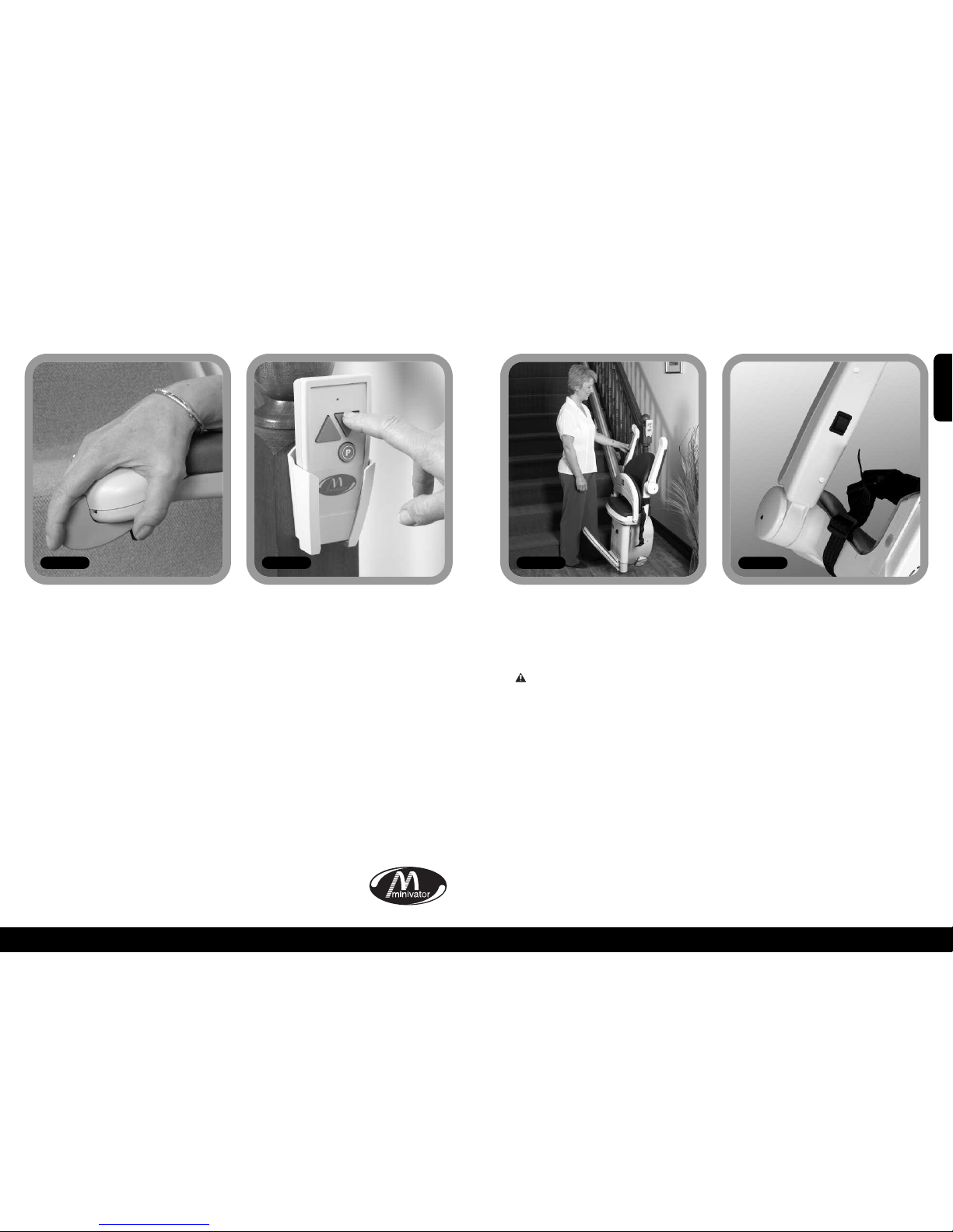
SAFETY PRECAUTIONS
NEVER
Swivel the seat without the lap belt
fastened.
NEVER
Mount or dismount the swivel seat unless
it is locked in position.
NEVER
Try to operate the swivel seat whilst the
stairlift is in motion. (As a safety
precaution, should you try to use it whilst
the lift is in motion, it will cause the lift to
stop).
NEVER
Attempt to travel up or down the staircase
unless the seat is in the correct position
(i.e. facing directly across the staircase).
ENGLISH
Operating your Minivator 1000
In some installations a hinged track option
may be necessary: usually to move the
track out of the way of a doorway at the
foot of the stairs. The hinged track is fully
automatic in operation and will function
as follows:
Going up the stairs
Mount the stairlift as previously directed
and push the operating toggle in the up
direction. The stairlift will, after a short
delay, move up the stairs. Once the lift has
passed the hinged track section it will stop
–KEEP THE TOGGLE PRESSED IN
THE UP DIRECTION. At this time the seat
will beep three times whilst the hinge
track automatically folds itself away. When
the hinge is fully folded the stairlift will
continue to the top of the stairs.
Going down the stairs
Mount the stairlift as previously directed
and push the operating toggle in the
down direction. The stairlift will, after a
short delay, move down the stairs. Before
the lift has reached the hinged track
section it will stop (Figure 11) – KEEP THE
TOGGLE PRESSED IN THE DOWN
DIRECTION.
At this time the seat will beep three times
whilst the hinge track automatically folds
open itself. When the hinge is fully open
the stairlift will continue to the bottom of
the stairs.
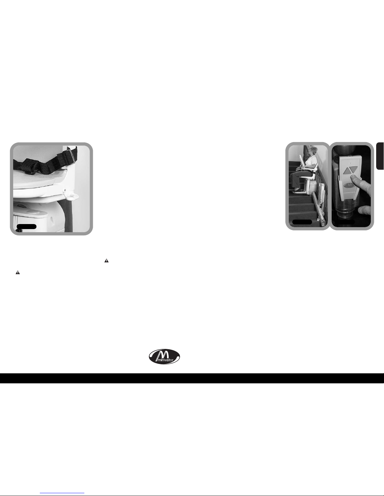
Parking the Stairlift
WHEN THE STAIRLIFT IS NOT IN USE IT
SHOULD BE MOVED TO ITS PARK POSITION
SO THAT IT DOES NOT CAUSE AN
OBSTRUCTION.
THE STAIRLIFT DOES NOT CHARGE WHEN
IT IS PARKED AT THE BOTTOM OF THE
STAIRS.
Hinged track
powered (optional)
Topark the stairlift, press and hold the P
button on the handset (Figure 12). The lift
will travel up the stairs to its park position
and the hinge will automatically fold itself.
If you release the P button the lift or track
will stop moving. To continue, press and
hold the P button again. After a short delay
movement will start again.
WARNING
BEFORE YOU OPERATE THE HINGED TRACK
PLEASE REMOVE ANY OBSTACLES WHICH
MAY OBSTRUCT THE TRACK.
Before raising the manual hinged track park
the stairlift on the charge points, above the
hinge, or at the top of the stairs.
Your stairlift will not work unless the track
has been lowered.
Hinged track
manual (optional)
Figure 12
Figure 11