manuals.online logo
Brands
  1. Home
  2. •
  3. Brands
  4. •
  5. vimec
  6. •
  7. Stairlift
  8. •
  9. vimec STAIRLIFT V70 User manual

vimec STAIRLIFT V70 User manual

30 - 04 - 2010
Vimec s.r.l
Via Parri, 7 - 42045 Luzzara - Reggio Emilia- Italy
Tel. + 39 0522 970 666 - Fax. + 39 0522 970919
www.vimec.biz
STAIRLIFT V70
USE AND MAINTENANCE Page 02 - 16
ASSEMBLY ISTRUCTIONS Page 17 - 52
SPARE PARTS MANUAL Page 53 - 64
MANUAL CODE
7 5 1 2 0 5 3
VIMEC reserves the right to make modications and changes to its products at any time in response to technological deve-
lopments.
DATE ____________ APPROVED ____________
Original instructions
2
7502050
CONTENTS OF THE MANUAL
1. Features of your stairlift Vimec Simplicity 950 Pag.3
2. Operating your Vimec Simplicity 950 Pag.4
3. Safety and servicing Pag.10
4. Routine care and cleaning Pag.11
5. Appendix 1 Pag.12
6. Appendix 2 Pag.13
7. Appendix 3 Pag.14
USE AND MAINTENANCE
INTRODUCTION
Thank you for choosing a Vimec stairlift. Please read these operating instructions carefully.
Your Vimec stairlift has been designed and builtwith careful attention to detail. In order
to obtain many years of trouble free use please follow the instructions, paying particular at-
tention to the care and maintenance requirements. Vimec recommend that you do not under-
take any maintenance tasks other than the routine care and cleaning explained in this
handbook. Please contact your Vimec dealer or our Customer Service Department in your
country if your stairlift requires attention and we would be pleased to help you.
STANDARD NORM
Vimec has been accredited as conforming to the international standard of manufacturing,
recognised by the award of UNI EN ISO 9001 Vision 2000. All Vimec stairlifts are built and
tested to conform to the British Standard for stairlifts (BS5776) :1996 as well as ISO 9386-2.
They also carry the CE mark.
Vimec are audited regularly to ensure we continue to conform to ISO 9001 and this provides
you with the assurance of using a high quality and well manufactured product.
3
4
2
65
1
7
6
3
7502050
1) FEATURES OF YOUR VIMEC V70
1- FOLDING SEAT
2- SWIVEL SEAT
3- INFRA RED REMOTE CONTROL
4- FOLDING FOOTREST WITH SAFETY EDGES
5- CONTROL LEVER WITH EMERGENCY STOP (RED MUSHROOM PUSH BUTTON)
6- FOLDING ARMRESTS
7- DIAGNOSTIC DISPLAY
FIG.1
4
7502050
2) OPERATING YOUR VIMEC V70
2.1) Key switch
Your Minivator stairlift is tted with a key switch (Fig. 2).
The stairlift cannot be operated unless the key is
inserted and turned to the on position.
The keyswitch is provided to enable you to lock the
stairlift to prevent it being used by others (for example
children).
However, it can be left in the on position if desired.
If you remove your key for safety reasons, please
ensure you put it in a safe place.
If the keyswitch is turned off the lift will continue to
charge.
2.2) On/off switch
As well as a key switch your stairlift is tted
with an on/off switch (Fig. 3) on the bottom, side panel
of the lift.
Ensure that this is left in the ‘ON’ position. The
fault diagnosis display panel will be illuminated to
indicate this.
If you intend to be away from home for a long period,
and decide to switch off the mains supply, it is important
that you also switch off the lift from this on/off switch.
This will ensure that the lift batteries will remain charged
while you are away.
2.3) Diagnostic display
The stairlift is tted with a diagnostic display
(Fig. 3) that displays a code to help diagnose faults.
Refer to Appendix 3 for an explanation of the diagnostic
codes. If you
should experience a problem with your lift please
examine the display and make a ote
of any codes that are displayed.
Please inform the customer services operator of these
codes when reporting any faults.
2.4)Operating lever
Before using your stairlift, MOST IMPORTANTLY
please ensure the stairs are clear of other people, pets
or any objects which may obstruct your stairlift. Then
next, ensure that the arms, footplate and seat are folded
down for use to ensure your safety. (Fig. 4).
BEFORE OPERATING YOUR STAIRLIFT
ALWAYS FASTEN YOUR LAP BELT.
Your Vimec stairlift is operated by simply pressing and
holding the operating lever in the direction you wish to
travel (Fig. 5). The stairlift will automatically stop when
the switch is released or the stairlift has reached the
end of its travel.
PLEASE NOTE: In the interest of safety, initial
FIG.2
FIG.3
FIG.4
5
7502050
activation of the stairlift is delayed by 1 second from
pressing and holding the operating lever, to avoid
accidental operation. If the switch is released while
the lift is in motion, the lift will stop and a delay of 1
second will occur before the switch will re-start the lift.
When changing the direction of travel the delay will be
3 seconds before the lift begins to move.
2.5) Hand control
The hand control (Fig. 6) is used to call the stairlift
to the desired floor or to operate the slide-track
(if installed). The control may also be used by an
attendant control where the user is unable to operate
the stairlift themselves.
The attendant should always remain off
the staircase until the stairlift is
stationary.
2.6) Folding your stairlift
Your Vimec V70 seat, armrests and footrest can be
folded to allow easier passage up and down stairs
when it is not in use (Fig. 7).
SAFETY PRECAUTION!
always return the stairlift to its stowed position.
i.e. with armrests, seat and footrest folded and the
chair parallel to the track as shown in gure 7, so
that exits are not obstructed.
2.7) Opertaing the swivel
A swivel seat is provided to enable you to mount/
dismount the seat more easily at the top of the stairs
by swivelling you on to the landing.
FIG.5
FIG.6
FIG.7
6
7502050
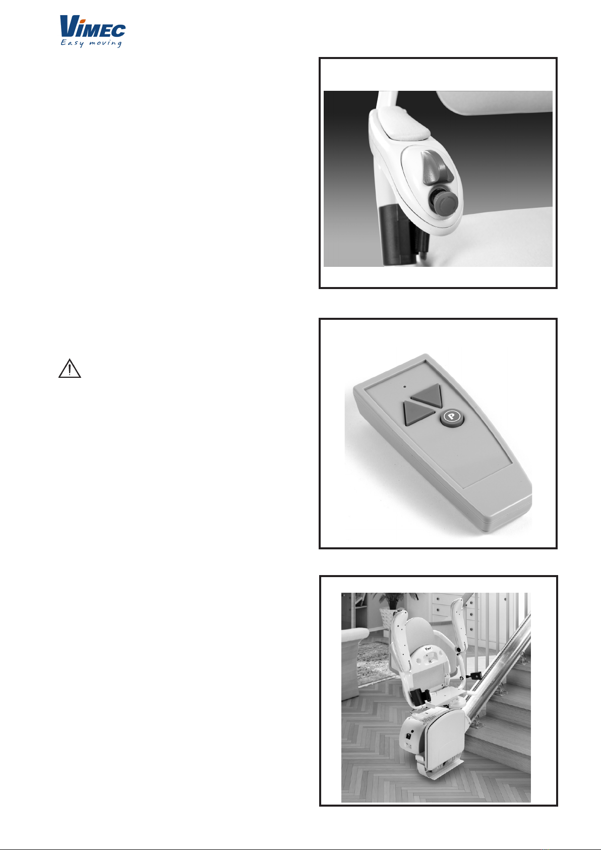
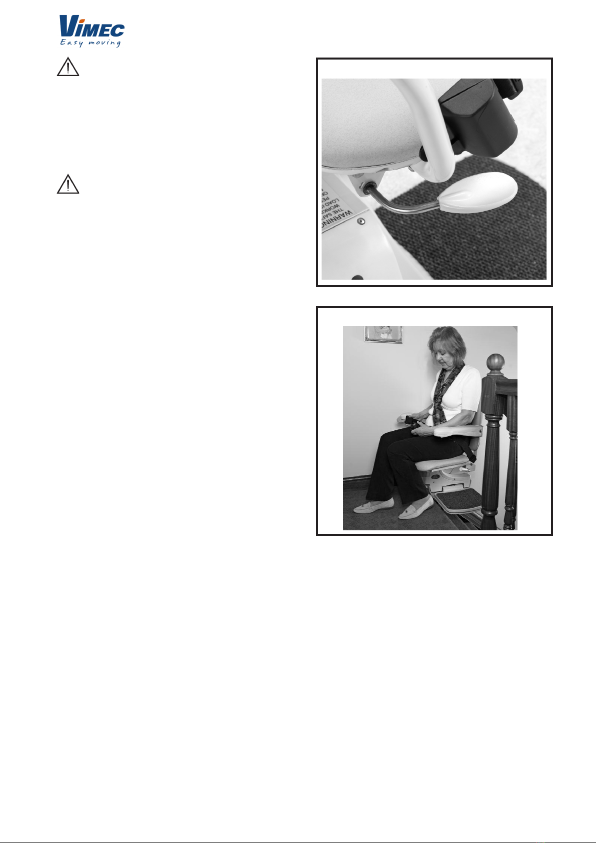
To operate the seat swivel, wait until the stairlift
has stopped.
To swivel the seat hold the swivel lever down (Fig.
8). When the seat reaches 90 degrees it will lock in
position.
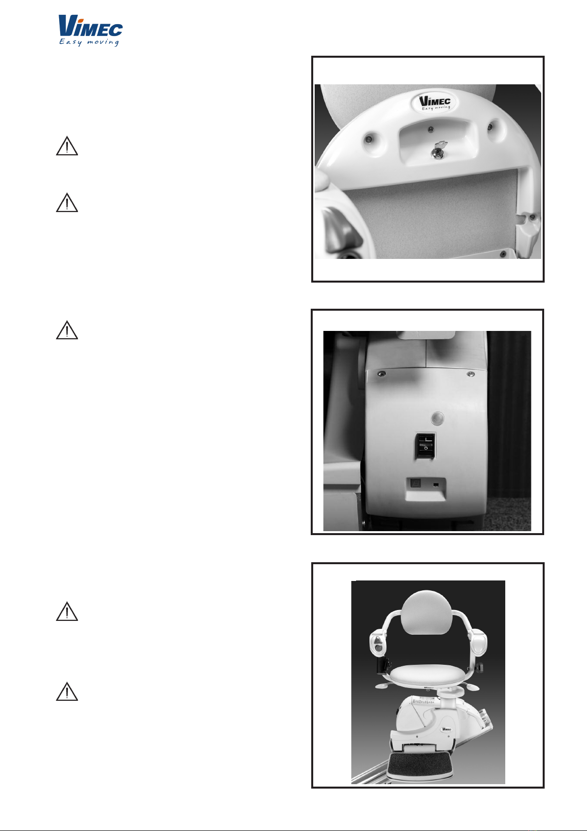
You should not attempt to leave the seat until it has
rmly ‘clicked’ into its locked position (Fig. 9).
To swivel in the opposite direction follow the same
procedure.
SAFETY PRECAUTIONS :
NEVER
Swivel the seat without the lap belt
fastened.
NEVER
Mount or dismount the swivel seat unless it is
locked in position.
NEVER
Try to operate the swivel seat whilst the
stairlift is in motion. (As a safety precaution,
should you try to use it whilst the lift is in motion,
it will cause the lift to stop).
ALWAYS
Use the swivel seat to travel up or down
the staircase in the correct position (i.e.
facing directly across the staircase).
2.8) Hinged track
Manual (optional)
In some installations a manual hinged track may be
necessary, usually to move the track out of the way of
the doorway at the foot of the stairs.
Before raising the manual hinged track, park the
stairlift near the hinged track or at the upper oor.
- Parking the Stairlift
WHEN THE STAIRLIFT IS NOT IN USE IT SHOULD
BE MOVED TO ITS PARK POSITION SO THAT IT
DOES NOT CAUSE AN OBSTRUCTION.
THE STAIRLIFT DOES NOT CHARGE WHEN IT
IS PARKED AT THE BOTTOM OF THE STAIRS (IN
CASE OF HINGED TRACK).
Your stairlift will not work unless the track has
been lowered.
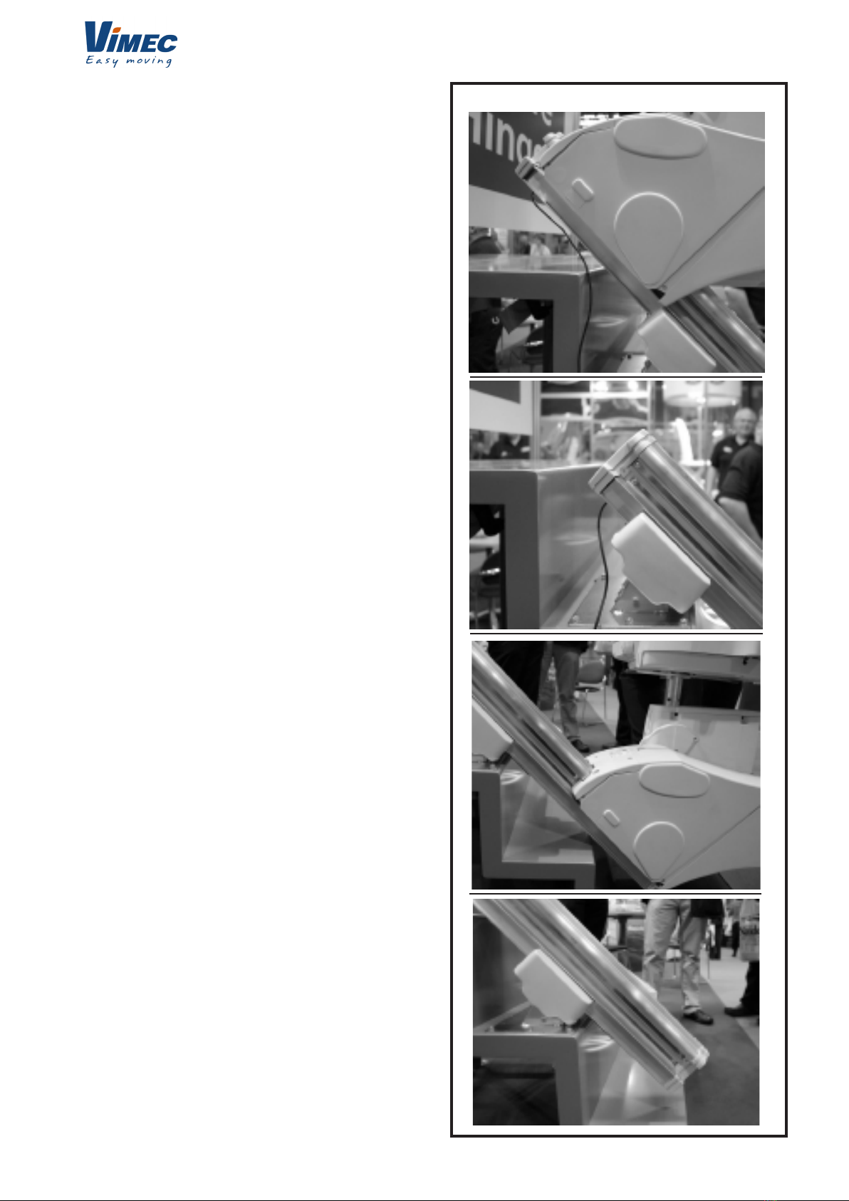
2.9) Motorised Slide Track
SlideTrack is a revolutionary addition to solutions
offered by the various types of stairlifts, eliminating the
need for installing hinged track on straight staircases.
• SlideTrack eliminates the potential danger of being
trapped, common to all hinges.
• SlideTrack’s minimum intrusion on either side of the
FIG.8
FIG.9
staircase reduces the risk of being trapped.
• Automatic operation makes SlideTrack easy to use.
• SlideTrack is the most suitable and accurate
alternative to hinged track.
• SlideTrack is easy to use, especially compared to a
standard hinge.
• Basically, SlideTrack guarantees safe use, it is easy
to install and use.
SlideTrack is shorter overall than track with a hinge.
When the lifter is in the parked position on the low part
of the staircase, SlideTrack does not reach the upper
landing.
When the track comes to its nal position on the upper
landing, it stops. The stairlift will continue along the
track until it reaches the end of the track.
Likewise, when it moves down the track it will continue
with the lifter until it reaches the ground oor where it
stops. The lifter will continue to move until it reaches
the end of the track.
7
7502050
How does the user start up the SlideTrack:
SlideTrack operates automatically: the user starts the
lifter as usual with the lever and SlideTrack will move
as requested.
The SlideTrack safety features
SlideTrack has safety guards on both ends. If the track
hits an obstacle it stops and can only proceed again
once the obstacle is removed.
SlideTrack is supplied with a CE marked manual
operation device for use in case of emergency.
SlideTrack length calculation
We will calculate the best track length for you if you
give us the distance from the upper point to the oor
and the staircase angle.
If you prefer to make your own calculations of the track
length, here is what you should do:
First measure from the upper point to the oor in mm:
this is measurement A in the diagram below.
Then measure the staircase angle.
In short, using the table below, identify value B (track
reduction from the point) and subtract it from your total
length A. The number will be the nal track cut length.
FIG.10
8
7502050
FIG.11
FIG.12
FIG.13
Track reduction from the point values
Angle = Value B Angle = Value B
37° = 81 40° = 79
38° = 81 41° = 78
39° = 80 42° = 77
Angle = Value B Angle = Value B
43° = 76 47° = 71
44° = 75 48° = 70
45° = 74 49° = 68
46° = 72 50° = 66
Track cut length
A (from the upper point to the oor in mm) less
B (track reduction from the point)
equals C (total track cut length)
For example:
Dimension A = 3250mm
Angle = 45°
3250 - 74 = 3176
Final track cut length
How to obtain a standard nish:
SlideTrack was designed to end with the platform
aligned vertically to the distance from the point, as
shown in gure 12.
This end position can be changed to shorten the
height of platform landing at the top of the staircase,
consequently moving the upper limit ramps downwards
towards the track. In addition, this will create lateral
play between the platform edge and the distance from
the point.
We recommend keeping this play to a minimum,
preferably less than 50 mm.
It may not always be possible to reach intrusion less
than absolute zero when SlideTrack is in a completely
high position. The lower intrusion is regulated by the
staircase angle and by the height of the rst riser.
In general the smaller the rst riser (D) is, the less the
lower track (F) intrusion will be; and the steeper the
angle, the less the lower intrusion (F) will be.
In most applications, less than zero intrusion is not
necessary since the door lintel (door frame) is normally
at the end of the rst point. It is usually 20mm broad. In
this situation SlideTrack can be adapted with a real zero
track intrusion which meets the obstacle elimination
requirement from the entrance door below.
Standard
nish
Distance from
the point
Height of rst riser
9
7502050
FIG.14
Technical specications
Minimum track length: 2 m
Maximum track length: 5 m
Minimum track angle*: 37°
Maximum track angle: 50°
Maximum load: 120 kg
Minimum pivot radius: 695 mm
* SlideTrack can be adapted to staircases of less than
27°. Nevertheless the track will reach the oor only
where the riser height is not high.
As the staircase angle decreases, the riser height must
decrease in relation, otherwise the track will block the
hallway.
Installation time
It takes the same amount of time to install SlideTrack
as it does a standard track; it is quicker and simpler
than installing a traditional hinged track.
How to order
Simply give us the distance from the upper point to the
oor and the staircase angle and we will calculate the
SlideTrack length for you.
How do we know if a less than zero intrusion is
possible.
Dimension D is the height of the rst riser. This is the
height that regulates the lower intrusion of the track.
The table on the left shows the maximum height of the
rst riser, at a given angle, where an absolute zero
intrusion is possible. A height of rst upper riser, at a
given angle, will give a minimum intrusion.
For example: on a 45° staircase, a rst riser up to 173
mm will give an intrusion of less than zero. On a 45°
staircase a rst riser that is more than 173 mm will
have less track intrusion.
How do we know the upper track projection.
The diagram below shows the upper projection when
SlideTrack comes to the limit at the top of the staircase.
Dimension E is the upper projection, meaning the track
distance from the upper point in the landing area.
The table on the left shows the upper projection (E)
with a given angle of the staircase.
For example, on a 45° staircase, the upper projection
will be 195 mm.
What type of lower track intrusion will there be with
a typical rst riser of 200 mm
Dimension F in the diagram below shows the lower
intrusion found with a typical rst riser of 200 mm. The
table on the left gives the details of the dimensions for
a staircase with a given angle and a rst riser height
of 200 mm.
If the architrave or obstacle distance from the rst
point is greater than Dimension F, the installation of a
SlideTrack instead of a hinge will be acceptable.
For example, a staircase with a 45° angle and a rst
riser height of 200 mm will have an intrusion of less
than 27 mm.
D: Maximum height for a maximum intrusion less
than 0
E: Upper projection (mm) at a given staircase angle
F: Lower intrusion at a given angle presuming a
rst riser of 200 mm.
Height of rst riser
10
7502050
3) SAFETY AND SERVICING
We advise that your stairlift is serviced after the rst 12
months and thereafter AT LEAST EVERY
12 MONTHS.
This work must be carried out by a competent person,
i.e. a Minivator approved dealer.
If in doubt, please contact the Minivator Service De-
partment on 01384 408700.
If you own your stairlift and no longer require it your
dealer or Minivator may be interested in
purchasing it.
3.1) Warnings and precautions
NEVER: Allow more than one person to use the stairlift
at any one time.
The maximum carrying capacity is 120kg (19 stone/
265lb).
NEVER: Allow children to play on or with the stairlift.
NEVER: Allow water to come into contact with the
components in the stairlift. If you have to
transport liquids DO SO WITH CARE.
NEVER: Place objects in the track, or leave objects on
the stairs, where they could come into
contact with the lift in operation. Your stairlift is tted
with sensitive side edges and
undertray on the footplate, which will automatically stop
the lift if it detects any
FIG.15
FIG.16
2.10) Emergency hand winding
instructions
In the unlikely event that the lift has a total power
failure or runs on to the nal track stops there is an
emergency hand winding procedure. Please follow
these steps:
1. Switch off the stairlift with the key.
2. Insert the emergency hand winding knob (Fig. 15).
3. Turn the knob in the direction indicated for the
required movement.
4. When the desired position is reached remove the
hand winder and switch the lift on.
If in any doubt contact your local Vimec approved
dealer or service centre.
2.11) Trapped articles
Your stairlift is tted with safety edges on the bottom of
the footrest and on the lift itself that will stop the stairlift
should any article become trapped by the footrest
(Fig. 16).
To remove the article reverse the stairlift away
from the object then have the object removed from
the staircase. Proceed on your stairlift as normal.
11
7502050
obstructions.
NEVER: Use the stairlift without using the lap belt, or
any other safety belts or harnesses tted.
NEVER: Use the stairlift in a standing position.
ALWAYS: Keep your FEET ON THE FOOTPLATE
whilst the stairlift is in motion, and try to avoid your
feet hanging over the edges of the footplate.
NEVER: Swivel the seat until the lift has come to a stop
at the top or bottom of the staircase.
ALWAYS: Fold the chair when it is not in use, to avoid
obstructing exits.
4) ROUTINE CARE AND CLEANING
4.1) Battery care and charging
Your stairlift is battery powered and will continue to
work for a period of time even if you have a power cut.
You should normally be able to travel up and down the
stairs at least 10 times without needing to charge the
batteries, however you should always ensure that there
is sufcient lighting to allow safe travel, especially at
each end of the track where you get on and off the lift.
The stairlift has a continuous load system.
In other words, the batteries can charge in any position
the stairlift is parked.
If the stairlift makes a beeping noise when it is not in
use IT IS NOT CHARGING.
Please check that the power supply for the stairlift is
switched on. If it is switched on and the beeping conti-
nues please contact your local Vimec approved dealer
or service centre.
4.2) Care and cleaning
Before cleaning any part of your stairlift, please ensure
you have removed the key. The stairlift is manufactured
from a variety of materials, all with easy “wipe clean”
surfaces. The seat and body covers can be wiped over
with a damp, NOT WET, cloth and a small quantity of
washing up liquid.
PLEASE DO NOT USE ABRASIVE CLEANERS,
BLEACH OR SOLVENT BASED CLEANERS, AS
THESE WILL DAMAGE THE SEAT.
To clean the track, rst send the stairlift to the top of
the stairs. The track can be cleaned with a damp cloth.
When most of the track is clean, move the stairlift to the
bottom of the stairs and nish cleaning the track making
sure that none of the cleaning debris falls on to it.
To maintain your stairlift in good mechanical order, it is
recommended that regular services are carried out by
qualied service engineers.
12
7502050
DIP 1 DIP 2
0N
0N
0N 0N
1 2 3 4
1 2 3 4
1 2 3 4 1 2 3 4
BATTERY POSITIVE
BATTERY NEGATIVE
IF ANY DIP SWITCHES ARE CHANGED, PLEASE TURN OFF
LIFT, WAIT 10 SECONDS, THEN POWER THE LIFT BACK ON.
CHARGE +
DIP SWITCH 1
DIP SWITCH 2
NO CONNECTION REQUIRED
INFRARED/RADIO
7 SEGMENT DISPLAY
9 WAY CON
NECTOR
8 WAY CON
NECTOR
BRAKE CONNECTOR
IINFRARED/RADIO LEARN
BUTTON
KEY:
HALF SPEED UP
HALF SPEED ON
PING DISABLE
UNUSED
FULL SPEED UP
FULL SPEED ON
PING ENABLE
UNUSED
HINGE DISABLE
DIRECTION
SLOW RAMP
UNUSED
HINGE ENABLE
DIRECTION B
FAST RAMP
UNUSED
V70 Left Hand and Right hand Standard
NO CONNECTION REQUIRED
5) APPENDIX 1
- Wiring diagram
MOTOR 2 (BLACK)
MOTOR 1 (WHITE)
13
31/01/2010
7502050
VIMEC S.r.l. “Original” Declaration of Conformity
_________________________________________________________
“EC” DECLARATION OF CONFORMITY
The manufacturer:
Via Parri n.7 , 42045 Luzzara (R.E.) ITALIA
Tel. 0522/970666 r.a. Fax 0522/970919
(Name and address of the person authorised to compile the technical le:
Name: Marco Marchetti
Address: Via Parri n.7 , 42045 Luzzara (R.E.) ITALY - Tel. +39/0522/970666)
states on his own responsibility that the stair lift for carrying a seated person, model:
V 70 – Serial Number:
conforms to the following directives:
- Directive 2004/108/EEC “Electromagnetic Compatibility”
- Directive 2006/95/EEC “Low Voltage”
- Directive 2006/42/EEC “Machinery Directive”
The Legal Representative
Ing. Giuseppe Lupo
Luzzara
6) APPENDIX 2
- Certicate of conformity
Draft
14
0
1
2
3
4
5
6
7502050
7) APPENDIX 3
- Diagnostic display
Display Code Meaning Self help action
None No display.
Press the toggle switch and see if display comes on.
Check that the main power switch on the lift is turned on.
If this does not clear the fault, contact your Vimec Servi-
ce Centre.
-- OK
0
Limit switch acti-
vated.
Check that the keyswitch is on and seat is fully swivelled
to the drive position. If this does not clear the fault,
contact your Vimec Service Centre.
1
Requires char-
ge.
The stairlift batteries require charging. Drive the lift to
the charge contacts if the ‘Okay’ code does not show
contact your Vimec Service Centre.
2 Not recharged Check that the battery charge is plugged. If it is plugged,
contact the Vimec service centre.
3
Over-run micro-
switch activated. Contact your Vimec Service Centre.
4
Safety edge (up/
down direction)
activated foo-
tplate.
Contact your Vimec Service Centre.
5
Final over-run
microswitch
activate
Contact your Vimec Service Centre.
6
A switch is active
i.e. Toggle Up,
Toggle
Down, IR Up, IR
Down or Learn.
Contact your Vimec Service Centre.
15
7
8
A
C
E
f
7502050
7
Batteries appro-
aching
critical level.
The stairlift batteries require charging. Drive the lift to
the charge contacts if the ‘Okay’ code does not show
contact your Vimec Service Centre.
8
Shows when
toggle switch is
activated in up/
down direction.
N/A
9
Shows when
toggle switch is
activated in
down/up direc-
tion.
N/A
A Hinge open. Contact your Vimec Service Centre.
B
A switch is ac-
tive
i.e. Toggle Up,
Toggle Down, IR
Up, IR Down or
Learn.
Contact your Vimec Service Centre.
C
The IR address
(dip switch)
does not match.
Contact your Vimec Service Centre.
D
The main power
relay is welded
closed.
Contact your Vimec Service Centre.
E
The main power
relay did not
close.
Contact your Vimec Service Centre.
F
Brake semi-con-
ductor
failed.
Contact your Vimec Service Centre.
GBrake not con-
nected. Contact your Vimec Service Centre.
16
H
l
P
u
7502050
H
The main power
relay has closed
early.
Contact your Vimec Service Centre.
LCurrent limit
exceeded. Contact your Vimec Service Centre.
N Half speed. If permanently showing, contact your Vimec Service
Centre.
O
The main control
board has a me-
mory problem.
Contact your Vimec Service Centre.
PPowered swivel
did not respond. Contact your Vimec Service Centre.
RNo charge cur-
rent.
Make sure that power supply is switched on from mains.
If it is contact your Vimec Service Centre.
UFaulty power
supply. Contact your Vimec Service Centre.
N/A Over current. Contact your Vimec Service Centre.
YFailure of control
card software Contact your Vimec Service Centre.
NOTE:
If the display is showing anything but the fault codes above it requires resetting.
Drive the lift off the charge contacts. Turn the main switch on the unit off for 10 secon-
ds and then back on
17
7602050
ASSEMBLY INSTRUCTIONS
CONTENTS OF THE MANUAL
1. PRE-INSTALLATION CHECK LIST Page 18
2. TRACK ASSEMBLY Page 18
3. FEET POSITIONING Page 22
4. LOADING THE POWER PACK Page 23
5. FITTING THE FOOTPLATE Page 25
6. FITTING THE SEAT Page 26
7. REMOTE CONTROL HANDSETS Page 29
8. TESTING Page 30
9. HANDOVER Page 32
10. ADDITIONAL INSTRUCTIONS FOR SLIDE TRACK USE Page 34
AND INSTALLATION
11. APPENDIX 1 Page 43
12. APPENDIX 2 Page 47
13. APPENDIX 3 Page 48
18
7602050
FIG.1
FIG.2
1) PRE-INSTALLATION CHECK LIST
1.1- Check that all of the required components are
available. You should have 6 boxes. These are
colour coded so that identication of any handed
components is simple. The table below shows the
colour of the boxes that you require.
COMPONENT Left hand Right hand
Footplate box Purple
Left
Green
Right
Purple Seat
Power pack
Blue
Fitting kit
Bottom track
section
Top track sec-
tion
e.g. a left hand lift comprises 2 purple and 4 blue
boxes; a right hand lift comprises 1 green, 4 blue and
1 purple boxes.
1.2- Installation tools required
- Toggle switch
- Short-circuiting switching connections
- 13mm Socket
- 17mm Socket
- 13mm Spanner
- 2.5mm Allen key
- 3mm Allen key
- 4mm Allen key
- 6mm Allen key
- 8mm Allen key
- No. 2 Pozi-drive
- Spirit level
- Small nose pliers
NOTE: The installation engineer must check with Vi-
mec for the latest installation manual issue number.
2) TRACK ASSEMBLY
Items required:
- Fit kit
Splice bars x 3
Track ends cap x 1
Red bag
8 x bolts
4 x grub screws
Final limit switch x 1
Over-run microswitch x 1
- Top track section x 1
- Bottom track section x 1
- Three xing support feet
Tools required:
- 6mm Allen key
- 3mm Allen key
- 2.5mm Allen key
- 13mm Spanner
2.1- Position the bottom section of the track (2m)
on the stairs with the splice holes at the top
as shown in (Fig. 1). Regardless of the hand
of the lift the rack should always be on the
left hand side of the track when looking up
the stairs.
2.2- Bolt in the splice bars to the bottom section
of track extrusion (Fig. 2) using 2 grub
screws for the top splice bar and the 4 bolts
in the bottom splice bars (from the red
ttings bag).
19
7602050
FIG.3
FIG.5
FIG.4
NOTE: Ensure that the splice bars are positioned in
the track in the correct orientation. The splice bar has
three at faces and one sloping face. The sloping face
MUST be positioned against the sloping face on the
extrusion as shown in (Fig. 3).
2.3- Position the top section of track adjacent to
the bottom section of track (Fig. 4).
2.4- For older machines: near the junction connect
the spade terminal connectors for the busbar charging
strip (Fig.5).
- For recent machines:
Kits now include a short copper strip that must be
placed across the track/busbar joint.
This replaces the copper adhesive tape and the
internal connection with the cables that were used
previously.
The installation instructions for this new connection
are explained below, and a copy is enclosed in each
installation kit.
1. Assemble the track as usual.
2. Slide the top of the load bar including the plastic for
approx. 100 mm.
20
7602050
FIG.7
FIG.8
FIG.9
FIG.10
FIG.6
3. Insert the copper connection bar at the end of the
load bar, behind the copper and in front of the plastic
(Fig.6).
4. Pull out the upper section of the load bar by approx.
10 mm. Now gently turn the end of the copper bar by
hand (Fig.7). If too much the contact brush will scratch
it.
5. Lightly push back the top of the copper load bar into
the plastic slot.
6. Bring the upper plastic section of the load bar
behind the connection bar (Fig.8).
7. Bring the upper part of the copper load bar above
the connection bar so that the connection bar is
pressed between the copper and plastic parts, as in
the bottom section (Fig.9).
8. Make sure that the upper and lower sections of the
load bars are as close as possible.
9. Foldaway tracks
Foldaway tracks are always connected from the top
with a cable running inside the track towards the lower
section. This connection is now made with a special
copper bar that gives continuity to the whole busbar.
2.5- Fix the track sections together (Fig. 11). The bolts
should be tightened in sequence:
a. left bottom
b. centre bottom
c. right bottom
d. left top
e. centre top
f. right top
Repeat this process until the bolts are all secure (torque
setting 8-9Nm).
NOTE: Ensure that the track is connected with all faces
level so that no step is present in the joint.
Pay close attention to the busbar charging strip – this
connection MUST be ush as shown in (Fig. 12).

Other vimec Stairlift manuals

vimec V64 B.I. User guide

vimec

vimec V64 B.I. User guide

vimec V 64 User guide

vimec

vimec V 64 User guide

vimec V65 B.I. User manual

vimec

vimec V65 B.I. User manual

vimec V64-74 B.I. User manual

vimec

vimec V64-74 B.I. User manual

vimec V65 B.I. User guide

vimec

vimec V65 B.I. User guide

vimec V65 B.I. User manual

vimec

vimec V65 B.I. User manual

vimec T10 User manual

vimec

vimec T10 User manual

vimec V65 B.I. User manual

vimec

vimec V65 B.I. User manual

Popular Stairlift manuals by other brands

Pride End-To-End Lift Chair Specifications

Pride

Pride End-To-End Lift Chair Specifications

Stair Climbers Kris instruction manual

Stair Climbers

Stair Climbers Kris instruction manual

Minivator Simplicity 950 Series user manual

Minivator

Minivator Simplicity 950 Series user manual

MOBILE STAIRLIFT ATLAS instruction manual

MOBILE STAIRLIFT

MOBILE STAIRLIFT ATLAS instruction manual

Hawle HW 10 user manual

Hawle

Hawle HW 10 user manual

Savaria K2 Plus owner's manual

Savaria

Savaria K2 Plus owner's manual

ThyssenKrupp Flow2 manual

ThyssenKrupp

ThyssenKrupp Flow2 manual

MediTek D120 user guide

MediTek

MediTek D120 user guide

Acorn 180 user manual

Acorn

Acorn 180 user manual

AmeriGlide RAVE owner's manual

AmeriGlide

AmeriGlide RAVE owner's manual

Bruno ELITE SRE-2010 Operator's manual

Bruno

Bruno ELITE SRE-2010 Operator's manual

ThyssenKrupp HomeGlide user manual

ThyssenKrupp

ThyssenKrupp HomeGlide user manual

AmeriGlide Rave 2 installation manual

AmeriGlide

AmeriGlide Rave 2 installation manual

Lehner Lifttechnik ALPHA user manual

Lehner Lifttechnik

Lehner Lifttechnik ALPHA user manual

manuals.online logo
manuals.online logoBrands
  • About & Mission
  • Contact us
  • Privacy Policy
  • Terms and Conditions

Copyright 2025 Manuals.Online. All Rights Reserved.