Minivator 1000 series Installation Manual
10
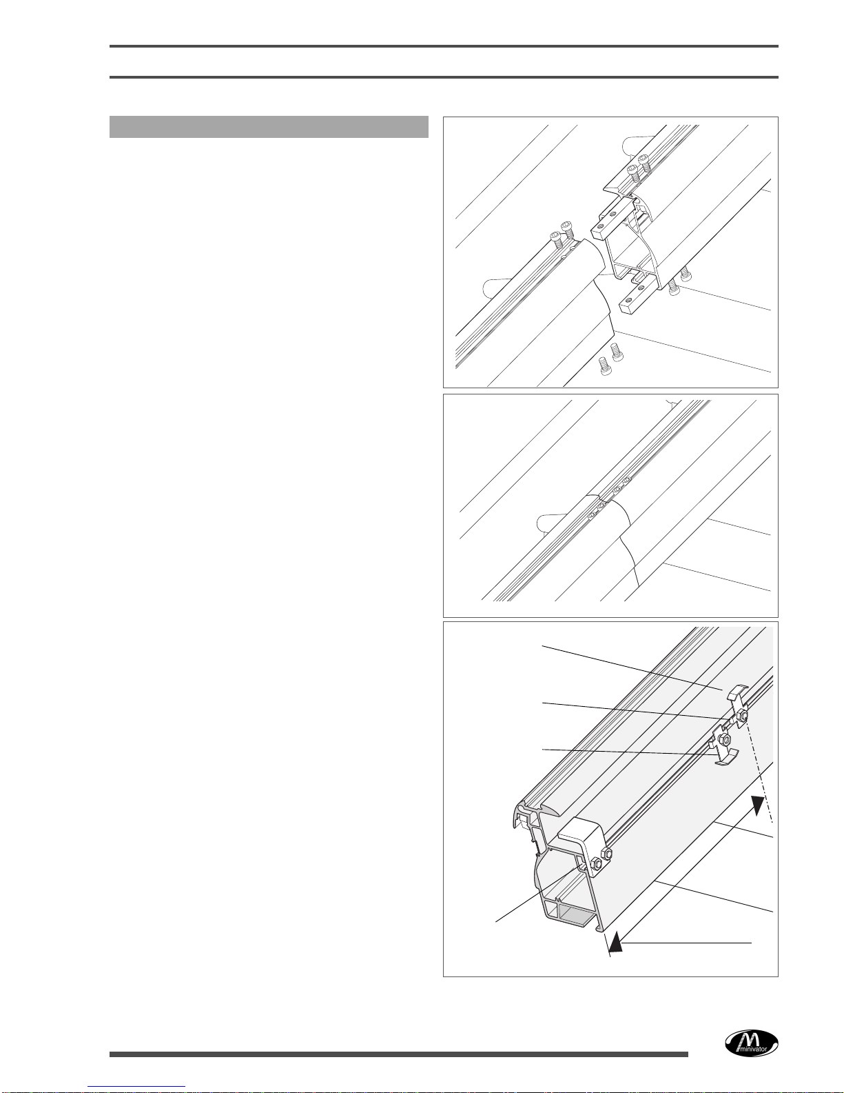
To assemble the track to the staircase
3 Stand the feet on to the stairs, with one
foot on the top tread, and one foot on the
first tread, with the spacing even in
between.
If possible fit one foot over the splice, or
as close as possible to it.
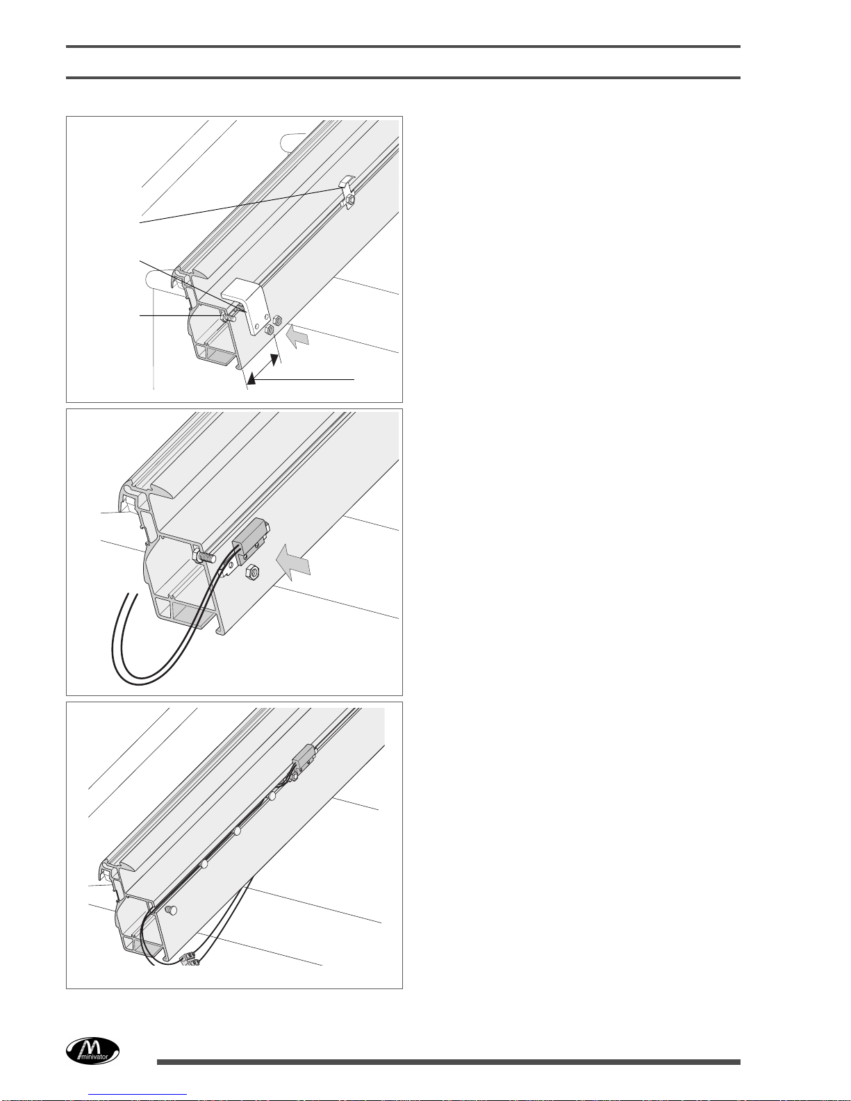
4 Offer the track assembly to the stairs, and
fix the feet to the stair treads, see Fig. 14
for fitting dimension.
With the screws supplied locate the feet
using three rear screws per foot.
5 Vertically align the track along its whole
length, using a spanner on the singlefront
adjuster on each foot (Fig. 13).
Do not tighten the screws until the track
angleiscorrectforverticalalignmentalong
its whole length.
Fig. 13
Screw the adjuster up or
down to achieve the
correct level - using a
10mm A/F wrench,
(under the foot) or a
6mm Allen key (before
fittting the fixing screw)
Finally ‘snap’ fit the
plastic covers over the
adjusting screws
When all the feet are
correctly adjusted
tighten all the fixing
screws.
Three fixing screws on each foot
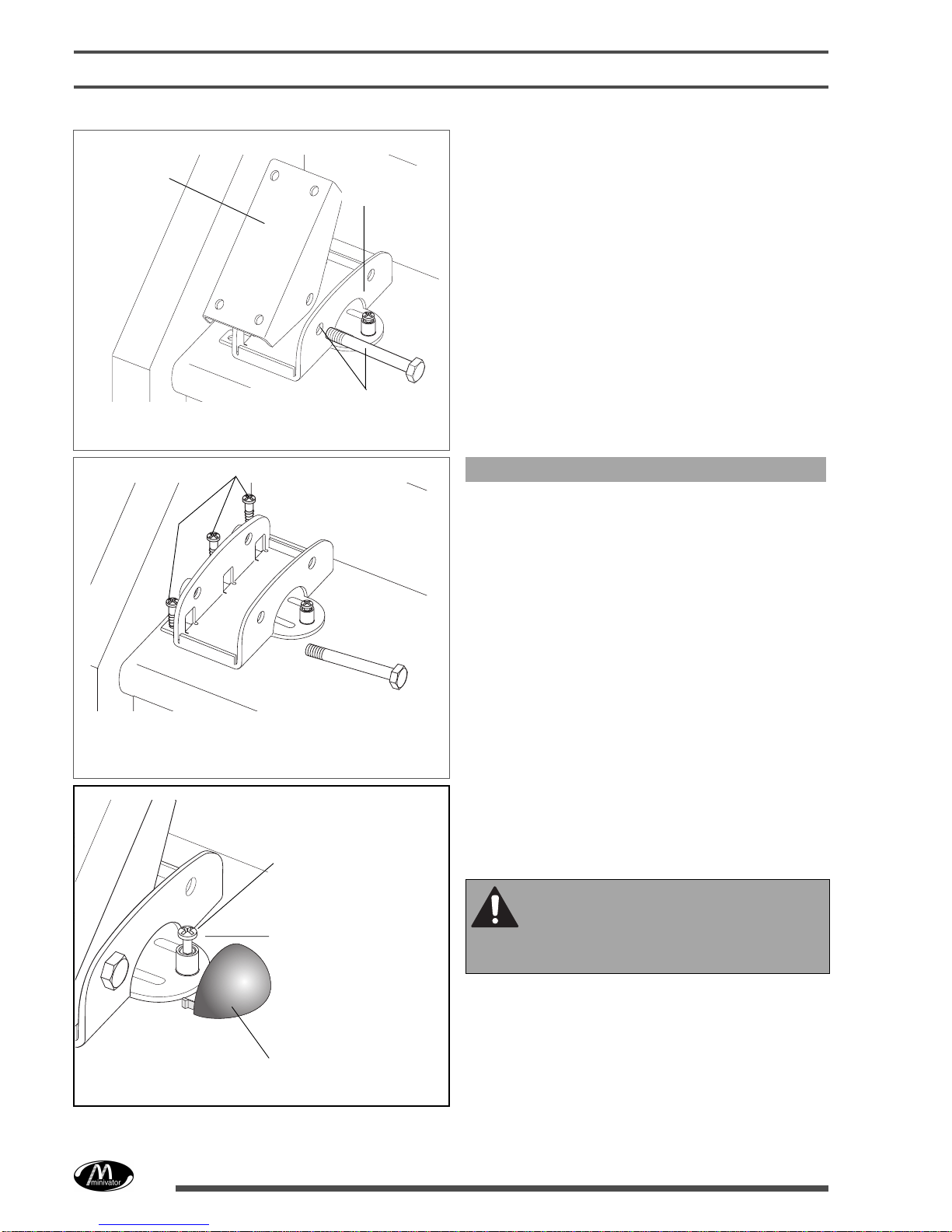
Fig. 12
Note the bottom foot component is shown in
isolation for clarity
Fig. 11
Mounting foot-
base
Mounting foot-
top bracket
Mounting foot-assembly bolt.
Use the hole closest to the
nose of the stair tread.
6 Tighten all feet to the track, and the feet
pivot bolts.
7 ‘Snap’ fit the protective plastic covers over
the adjuster assemblies.
Failure to align the track and feet
correctly prior to tightening the
screws will twist the feet and lead
to permanent damage.