Harman SR601 User manual

ATTENTION! STRICT ADHERENCE TO THESE INSTALLATION INSTRUCTIONS is required and will promote the safety of those installing this
product, as well as those who will ultimately use the lift for its intended purpose. Any deviation from these instructions will void the
LIMITED WARRANTY that accompanies the product. Additionally, any party installing the product who deviates from the INSTALLATION
INSTRUCTIONS shall be taken to agree to INDEMNIFY, SAVE AND HOLD HARMLESS the manufacturer from any and all loss, liability or
damage, including attorneys fees, that might arise out of or in connection with such deviation.
Stair Lift
SR601
INSTALLATION MANUAL
Part Number: 630-00065-01 Rev A

© 2015Harmar Mobility, LLC • All Rights Reserved
| www.harmar.com
2
Pinnacle 101 Stair Lift CONTENTS
Read and understand this manual prior to
attempting stair lift installations. Please
refer to the Owner’s Manual for Limited
Warranty information and operating instructions.
The Owner’s Manual must be given to the owner
of the lift before it is put into service.
Any alterations to the equipment without written
authorization by the manufacturer may void
the warranty.
Harmar lifts are designed to install with as little
assembly by the installer as possible. If you have
questions, concerns or comments, please contact
Harmar’s Technical Service Department.
Contents
PRELIMINARY CHECKS 3
Tools Required ...............................3
Included Parts ................................3
INSTALLATION PROCEDURES 4-12
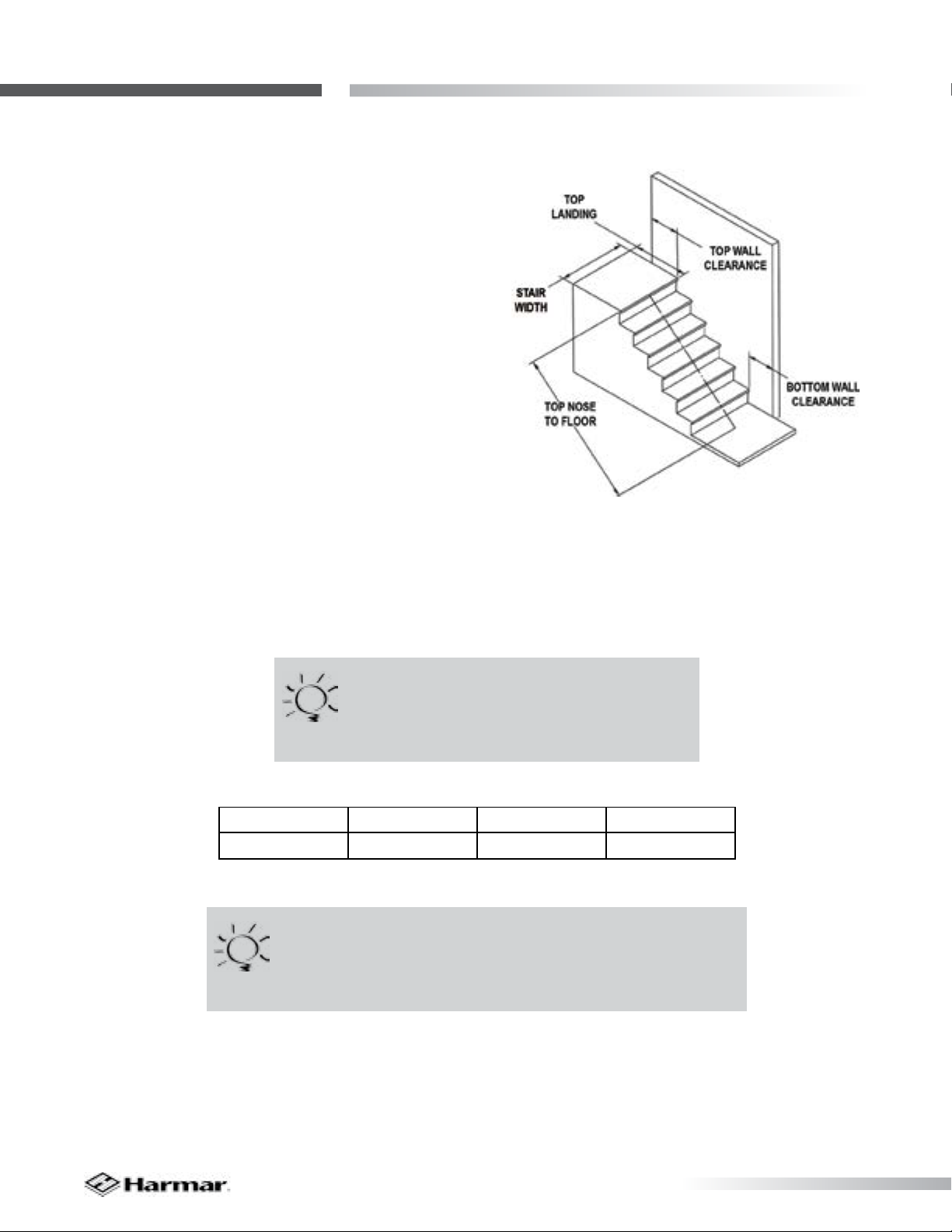
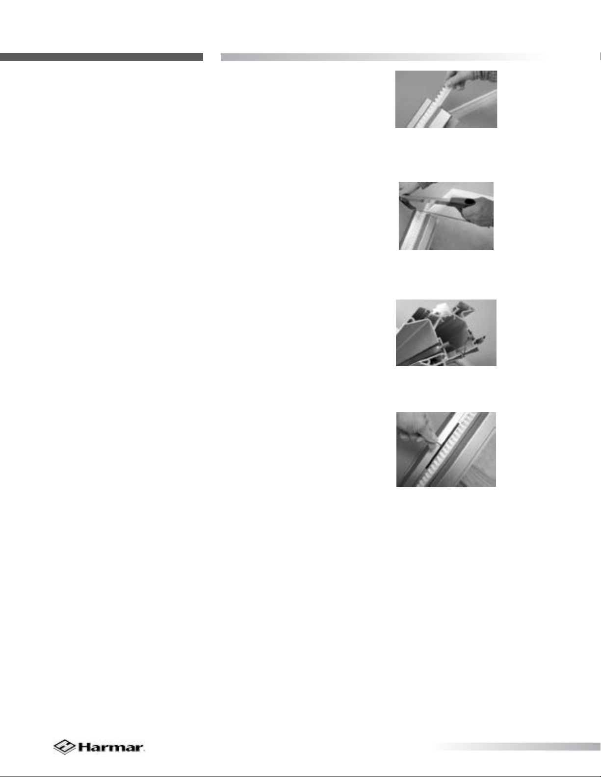
Determine Rail Length ........................4
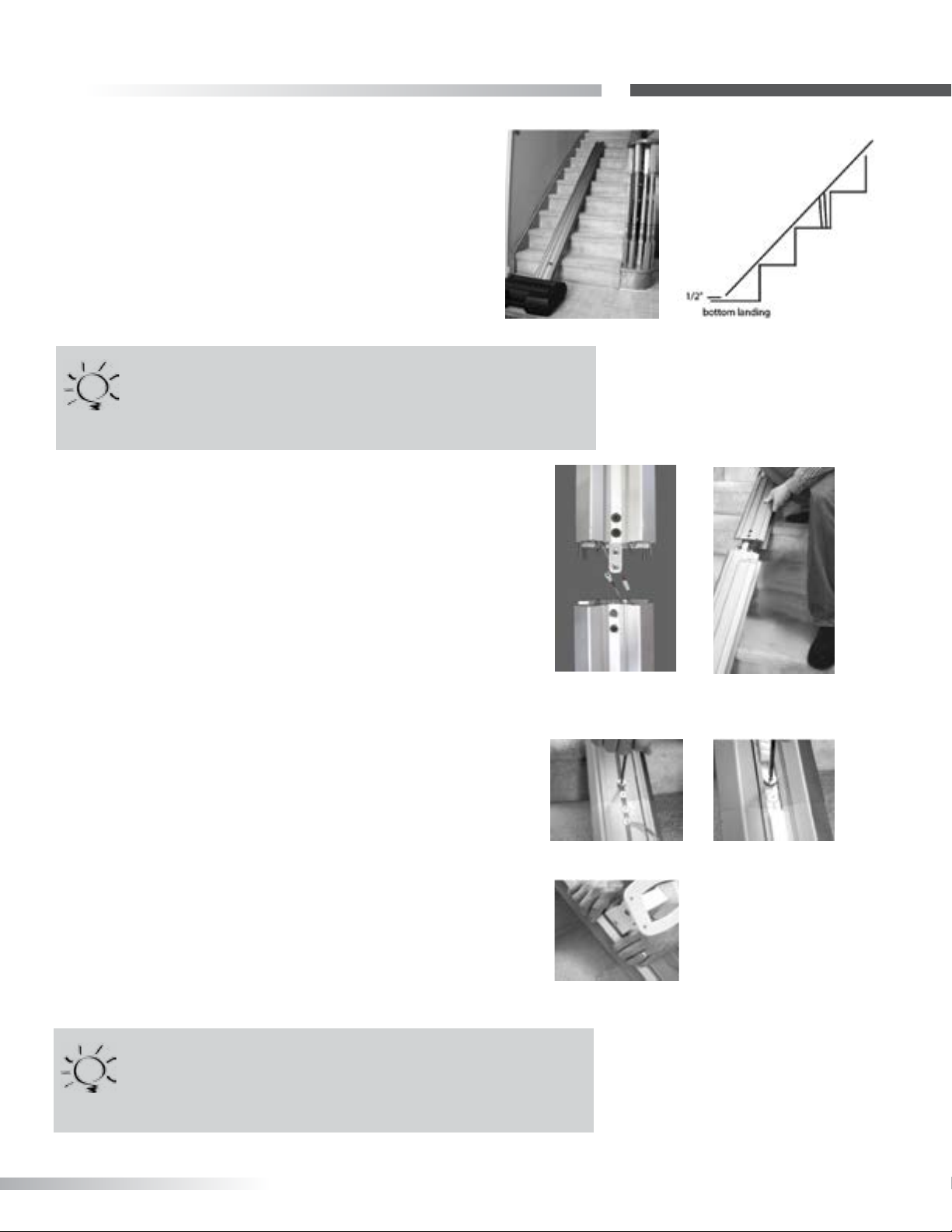
Rail Installation .............................5-6
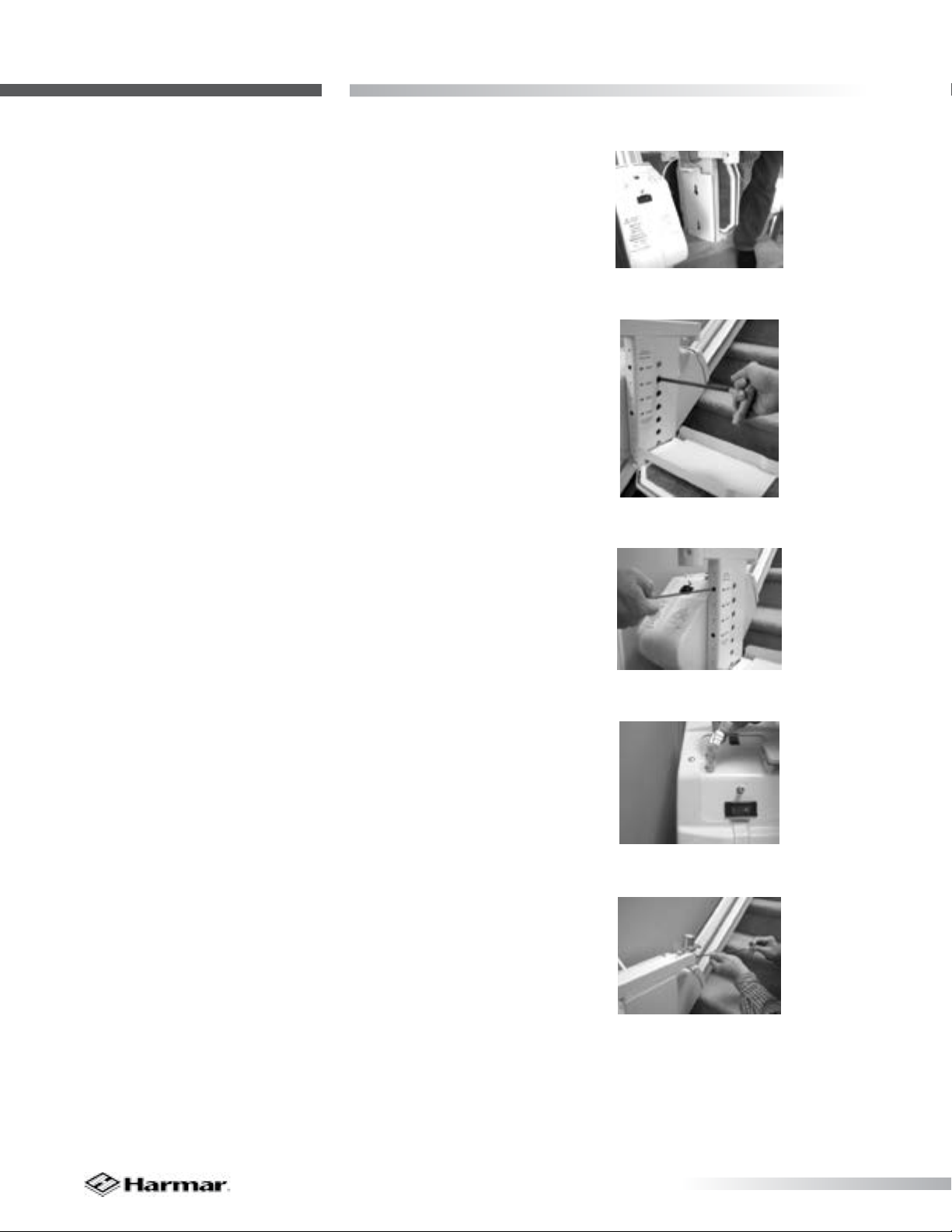
Chassis Installation............................7
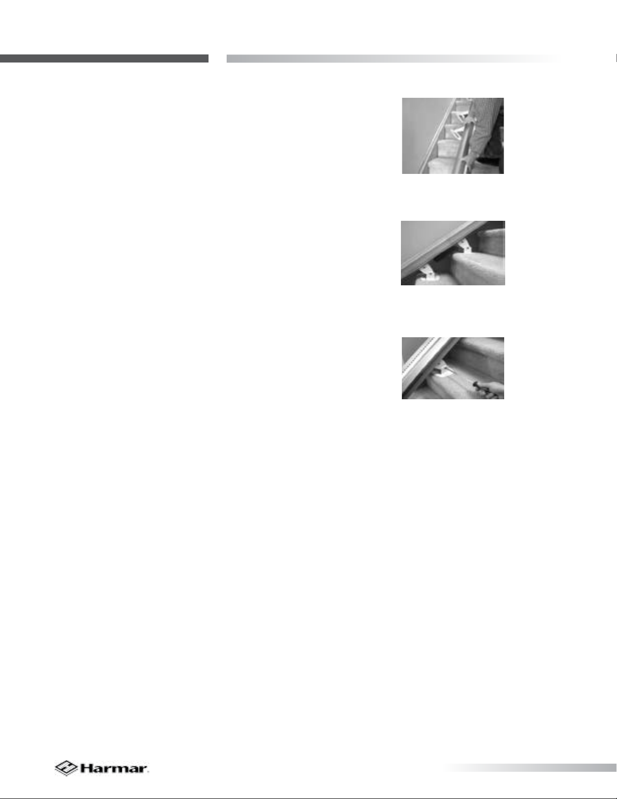
Final Rail Installation ........................8-9
Footrest And Seat Installation .............10-12
REMOTE CONTROL OPERATION 13
Remote Control Operation ...................13
Remote Control Reprogramming .............13
COMPLETION PROCEDURES 14-15
Test Armrest Control Switch..................14
Tighten Brackets .............................14
Set Upper And Lower Travel Limits............14
Test Safety Stop Switches..................14-15
Additional System Checks ....................15
SAFETY SYSTEMS TESTING 16
FOLDING RAIL INSTALLATION 17-20
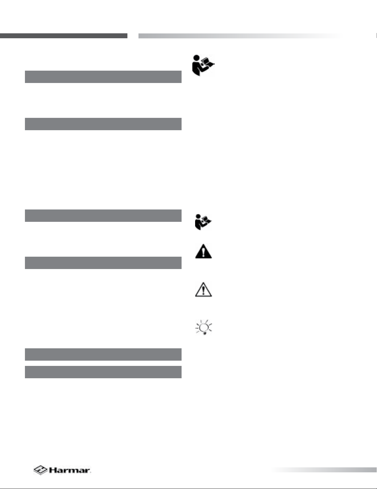
SYMBOLS USED IN THIS MANUAL
READ MANUAL - Pay close attention to
the instructions in the manual.
CAUTION - Hazardous situation. If not
avoided, could result in serious damage
to property.
WARNING - Hazardous situation. If not
avoided, could result in serious injury to
installer or user.
TIP - Helpful tips that will facilitate ease
of installation.
INDICATIONS OF USE STATEMENT
The Pinnacle 101 Stair Lift is to assist transfer of
patients or mobility impaired persons, up and down
between levels of a residential or private facility.

TEC0081 20150915 P/N: 630-00065 revA SR601 • Pinnacle 101 Stair Lift Installation 3
Pinnacle 101 StairPRELIMINARY CHECKS
Tools Required
The following is a suggested list of basic tools to
have on hand during installation.
Cordless drill
Allen wrenches (5/64”, 5/32”, 3/16”, 5/16”)
Phillips screwdriver (#3)
Nut driver (3/8”and 5/16”)
6-10” driver extension
T30 Torx bit (included)
Level
Hack saw or chop saw
SAE socket set
SAE wrenches
Tape measure
Volt Meter
Included Parts
Before beginning installation, please inspect and
check the box contents. Report any damage to your
dealer.
Chassis Box:
Chassis
In Tray
2 Wireless call/send hand controls
Power supply
Manual overide tool
Installation manual
Owner’s manual
Rail Box:
Bottom rail pre-installed with:
Bottom end plate
Charge strip wire harness
Bottom limit cam
Joint pins and joint brackets
(two-piece rail only)
Plastic gear rack
Top rail pre-installed with:
Charge strip wire harness
Rail accessories (plastic bag):
Top end plate
Compression bolts (2 sizes)
Self-cutting screws (1/4”-20 X 1”)
Torx T30 driver bit
Rail Bracket Box:
Rail brackets (2, 3, 4, or 6 per set)
Wood screws (#14 X 2” (4 per rail bracket)
Chair and Footrest Box:
Chair with seat belt
Footrest complete with:
Adjustable seat height frame
Plastic vertical cover
Nylon plugs (5)
Seat swivel post with fasteners
Rail parts (plastic bag):
Extra plastic racks (2 or 3)
Top limit cam

© 2015Harmar Mobility, LLC • All Rights Reserved
| www.harmar.com
4
Pinnacle 101 Stair Lift INSTALLATION PROCEDURES
A. DETERMINE OVERALL RAIL LENGTH
(Only if rail did not come pre-cut to length)
1: Determine any obstructions that will aect the
position and length of the rail. These may include
walls, doors, hallway orientation, etc.
2: Measure the overall length of the stairs from the
nose at the top landing of the stairs to the oor at
the bottom (nose to oor measurement, (128").
[Figure 4-1]
3: For a normal stairway with adequate space for a
landing, add 13" to the nose to oor measurement.
This will provide enough rail length to allow
the stair lift to be adjusted so that the oor-to-
seat height will be the same at both the top and
bottom (e.g., 141").
4: If the top landing has restrictions (i.e., a wall or
doorway), use the chart below to determine the
length of extension that should be used.
5: To cut the rail, use a standard 12”chop saw,
with a blade designed to cut aluminum.
Figure 4-1
Installation Site Electrical Requirements - The lift shall be connected to a dedicated
120V 15A electrical circuit.
Extension
7 in 9 in 11 in 13 in
3.9 in 5 in 6.1 in 7.2 in
Horizontal intrusion on top landing
TIP
Do not cut rail inside the house (aluminum
chips are very hard to remove from carpets)
TIP
DO NOT cut the end of the rail that contains the joint holes.
Remove the charger strips and wire harness before cutting.

TEC0081 20150915 P/N: 630-00065 revA SR601 • Pinnacle 101 Stair Lift Installation 5
Pinnacle 101 Stair
INSTALLATION PROCEDURES
B. RAIL INSTALLATION
1: Open the rail box and remove the contents.
2: Position the bottom rail (the rail with end plate
attached) directly on the stairs with the end plate
towards the bottom of the stairs and the plastic rack
facing up. Place an object that measures between
3/4 in and 1 in between end plate and the oor.
[Figure 5-1 and 5-2]
3: Position the two ends of the rail close together.
Locate and connect the plug on the ends of the two
power harnesses inside the two rail pieces. [Figure 5-3]
4: With the plastic rack facing up, slide the top
rail into the bottom rail and guide them together
using the pre-installed pins. Gently tap the top rail
if necessary to get them close together. Be cautious
not to pinch the power harness. [Figure 5-4]
5: Install two (2) joint fasteners and rmly tighten
with 3/16” Allen wrench. Then slide rack pieces
down to cover joint. [Figure5-5]
6: Turn over joined rails and install the remaining
two (2) joint fasteners and rmly tighten with 3/16”
Allen wrench. Then slide rack pieces down to cover
joint. [Figure 5-6]
7. Install rail brackets with label facing the wall by
loosening the screws and snapping each bracket
edge into the slot, or slide the brackets on from the
top of the rail. [Figure 5-7]
Figure 5-1
Figure 5-6Figure 5-5
Figure 5-4Figure 5-3
Figure 5-2
Figure 5-7
TIP
Use the chair box or another heavy object, like a toolbox, at
the bottom to prevent the rail from sliding down the stairs.
TIP
The brackets are tightened from one side only. It is
important that the bracket be installed with the nut side
facing the wall so when the rail is turned over to its correct
orientation the screws will be accessible.

© 2015Harmar Mobility, LLC • All Rights Reserved
| www.harmar.com
6
Pinnacle 101 Stair Lift INSTALLATION PROCEDURES
8.
A. For double rails, the rst rail bracket should
be tightened in place so when turned over
the back of the bracket touches the rear of
the rst step from the bottom landing. The
second and third brackets should be placed
and tightened on the steps on each side
of the rail joint, again so the back of the
bracket touches the rear of the step. The
fourth and nal bracket should be placed
on the last step before the top landing,
again tightening it so it touches the front of
the rear of the last step.
B. Tighten the rst rail bracket in place so
when turned over the back of the bracket
touches the rear of the rst step from the
bottom landing. Place the other rail on
the last step before the top landing, again
tightening it so it touches the rear of the
last step.
9. Turn the rail right side up (plastic side facing up).
[Figure 6-1]
10. Measure any obstruction from the wall (this
may include handrails, molding, light switches,
etc.) and adjust the edge of the brackets an equal
distance from the wall. The minimum distance will
be 1/2" from the wall or any obstruction.
11. The underside of the rail must be at least 2"
above the stair tread nose to provide clearance
for the footrest. To achieve this 2" clearance move
the rail and bracket forward. Once the clearance is
2", tighten all bracket nuts to hold the brackets in
position. To maintain the 2" clearance, and to hold
the rail in place, secure the bottom bracket to the
rst step from the oor with 2" wood screws, using
a 3/8" nut driver on a 6-10”extension of a cordless
drill. [Figure 6-2 and 6-3]
Figure 6-1
Figure 6-2
Figure 6-3

TEC0081 20150915 P/N: 630-00065 revA SR601 • Pinnacle 101 Stair Lift Installation 7
Pinnacle 101 Stair
INSTALLATION PROCEDURES
C. CHASSIS INSTALLATION
1. Remove chassis from the box. Lift the chassis
with the manual override hole (on bottom) facing
the downhill side of the stairs and gently slide the
chassis onto the rail until it makes contact with the
plastic rack. DO NOT LET THE CHASSIS FREE FALL
DOWN THE RAIL.
2. Use the installation switch (the black switch on
the top of the chassis) to move the chassis at least
24" down the rail, pushing gently on the chassis to
ensure the chassis does not pull any rack to the top.
3. Loosen, but do not remove, the four (4) seat-
leveling bolts two (2) on each side of the chassis)
and then align them vertically using a level. Firmly
tighten the two (2) bolts on the side of the chassis
facing the wall.
WARNING
Be careful not to trap ngers
between the rail and the chassis.
WARNING
Do not ride on the chassis or lift until
the install is complete.

© 2015Harmar Mobility, LLC • All Rights Reserved
| www.harmar.com
8
Pinnacle 101 Stair Lift INSTALLATION PROCEDURES
D. FINAL RAIL INSTALLATION
1. Install the remaining plastic rack pieces in the
upper rail. [Figure 8-1]
2. Use a hacksaw or chop saw to cut the last plastic
rack piece ush with the rail end. Place something
on the oor to catch debris or mark and cut the
rack outside. [Figure 8-2]
The exposed, cut end of the plastic rack should be
facing the top end of the rail (the factory-cut side
should butt against the lower rack).
3. Slide the top limit cam into one of the cam slots
(it doesn’t matter which side), and tighten the
pre-inserted Allen screw with a 5/64”Allen wrench.
This will be used to set the nal upper limits for the
stair lift. [Figure 8-4]
4. Remove charging strip from the rail box.
Connect charging strip connector to the power
wire that runs through the center of the rail from
the lower charging strips. [Figure 8-3]
Insert the two (2) charger strips into the keyed slots
at the top of the rail (while standing on the top
landing looking down). The charging strip with the
red wire should be inserted into the left slot with
the metal strip facing out. The charging strip with
the black wire should be inserted into the right slot
with the metal strip pointing out. [Figure 8-3]
Bend the red and black wire tabs in toward the
center of the track.
Insert excess cable into the rail, leaving the pigtail
with the Molex connector on the outside.
Figure 8-4
Figure 8-3
Figure 8-2
Figure 8-1

TEC0081 20150915 P/N: 630-00065 revA SR601 • Pinnacle 101 Stair Lift Installation 9
Pinnacle 101 Stair
INSTALLATION PROCEDURES
5. Install the end plate to the top of the track with
the four (4) self-cutting Torx screws using the
supplied T30 Torx bit. [Figure 9-1]
Figure 9-1
Figure 9-2
Figure 9-3
Figure 9-4
TIP
Too much torque applied to these screws
may result in damage. Take your time and
apply grease to threads.
6. Install one of the rack pre-compression screws
in the threaded hole in the top plate of the rail, and
tighten it as rmly as possible by hand with a 5/32”
Allen wrench. [Figure 9-2]
There are two (2) kinds of pre-compression screws:
• 3/4” for rails under 12 ft
• 1” for rails over 12 ft
7. Plug in the power supply at either end of the
rail, depending on the closest or most convenient
location of a wall power supply. Minimize wire length
and intrusion. [Figure 9-3 & 9-4]

© 2015Harmar Mobility, LLC • All Rights Reserved
| www.harmar.com
10
Pinnacle 101 Stair Lift INSTALLATION PROCEDURES
E. FOOTREST & SEAT INSTALLATION
1. Remove footrest from box and use the installation
switch to drive the chassis downward to a position
about 6" clear of the oor. This will provide a safe
area to install and adjust the footrest. Do not drive
the unit into bottom stop. [Figure 10-1]
2. Turn the red “ON/OFF”switch located on the top
of the chassis to the“OFF”position (0).
3. Position the footrest onto the two (2) seat-
leveling bolts on the outside of the chassis by
aligning the large opening at the slot ends of the
footrest. [Figure 10-2]
4. Ensure the footrest is fully engaged.
5. Check that the height of the seat base is
correctly set for the intended user. A seat height
guide is provided behind the plastic footrest
shroud. Consult with the client and use an existing
chair or walker with armrests as a guide.
If the height of the seat needs to be adjusted,
loosen and remove the four (4) bolts on the sides
of the seat base using a 5/32”Allen wrench. Adjust
the seat base up or down relative to the footrest
structure until the holes align, then replace and
securely tighten the four (4) bolts. [Figure 10-3]
6. Connect the footrest cable to the 6-pin
connector on the chassis. [Figure 10-4]
7. Position the keyed seat swivel post in the hole in
the seat base hole closest to the top of the stairs.
Securely tighten the two (2) bolts on the sides of the
hold using a 5/32”Allen wrench. [Figure 10-5]
8. Use the supplied white plastic plugs to secure
the vertical footrest shroud to the main footrest
cover plate.
Figure 10-1
Figure 10-2
Figure 10-5
Figure 10-3
Figure 10-4

TEC0081 20150915 P/N: 630-00065 revA SR601 • Pinnacle 101 Stair Lift Installation 11
Pinnacle 101 Stair
INSTALLATION PROCEDURES
9. Position the seat directly aligned over the
carriage and place onto the seat swivel post.
Depress the swivel lever until the seat is fully
engaged with the swivel post. Check the swivel
lever to test the locking mechanism. THE SYSTEM
WILL NOT FUNCTION IF PROPER ENGAGEMENT IS
NOT ACHIEVED. [Figure 11-1]
10. Connect the seat cable to the 8-pin connector
on the chassis. [Figure 11-2]
11. The armrest control is factory set for right-hand
operation. If the user prefers to operate the armrest
controls with their left hand, loosen the single
screw on the underside of each armrest and slide
each armrest upwards. Disconnect the plug on the
armrest control, switch the armrests, and reconnect
the plug. Replace armrests and tighten screws.
[Figure 11-3 & 11-4]
Figure 11-1
Figure 11-6
Figure 11-5
Figure 11-4
Figure 11-2
Figure 11-3
TIP
When the 6-pin footrest and/or the 8-pin
chair cables are connected to the chassis,
the black installation switch on the
chassis is disabled and will not function.
NOTE - If the lift is equipped with the optional key
switch on the armrest control, be sure it is in the
locked position with the key in the vertical position.
[Figure 11-5]
12. Turn the red “ON/OFF”switch located on the
top of the chassis to the“ON” (I) position. You
should hear a single beep and the LED indicator
light on the armrest control should cycle through
a test sequence, showing red, yellow and green
respectively. If any of the system controls or safety
sensors are engaged the LED indicator light will turn
to yellow. [Figure 11-6]

© 2015Harmar Mobility, LLC • All Rights Reserved
| www.harmar.com
12
Pinnacle 101 Stair Lift INSTALLATION PROCEDURES
Figure 12-1
1. If the LED indicator light is not green, check the
safety senors:
• Seat swivel sensor (seat should be in the
locked position)
• Footrest lower sensor (check by pushing in
on the safety pan on the footrest)
• Upper foot pan safety sensor (check by
pushing on the safety pan on the footrest).
• Front foot pan safety sensor (check by
pushing on the safety pan on the footrest).
• Uphill safety sensor (ensure nothing is
blocking upward passage)
• Downhill safety sensor (ensure nothing is
blocking downward passage)
If the LED indicator light is still not green after
testing sensors, turn the unit o and re-check all
wire plugs. Turn the unit on again and re-check the
LED indicator light cycle. When the LED indicator
light remains green the lift is ready to operate.
[Figure 12-1]
F. LED & AUDIBLE TONES
2. TONES INFORMATION
Minor faults
Single long beep (will reset once fault is cleared)
• Seat swiveled out of position
• Edge safety detected
• Under foot rest
• Current overload condition
• A Low battery voltage condition
Pulsing Beep
Lift stopped o of charge strip. Will sound after 30
second for 30 seconds. It will repeat ever 10 minutes
until lift is operated or returned to charge strips.
Tones Beeps
Runaway ....................................................................... 1
No Power ........................................................................2
Conicting Switches Footrest UP & Footrest DOWN ...............................3
Conicting Switches Obstruction UP & Obstruction Down.........................4
Conicting Switches Footrest DOWN & Obstruction UP ...........................5
Conicting Switches Footrest UP & Obstruction DOWN ...........................6
Conicting Switches STOP UP & STOP DOWN switches both Detected .............7
Conicting Switches STOP UP & STOP DOWN switches both not Detected .........8
Helix Only LIMIT Switch Dectected ...............................................9
Major Fault Codes

TEC0081 20150915 P/N: 630-00065 revA SR601 • Pinnacle 101 Stair Lift Installation 13
Pinnacle 101 StairREMOTE CONTROL OPERATION
A. REMOTE CONTROL OPERATION
1. Press and hold the
appropriate directional
button on the front of the
hand control.
The chair lift will operate with
or without a rider. All safety
sensors on the chair lift are designed to continue
to operate in their normal mode. The LED light
indicator on the armrest will display the appropriate
color.
2. If the chair lift fails to respond, this may indicate
the batteries are discharged and need to be
replaced. Remove the back cover of the control and
replace with commonly available AAA batteries,
ensuring that the polarity is correct.
Remote Call/Send Control Operation
NOTE - If the key lock option is installed the key
switch on the arm of the chair must be in the “ON”
position to use the remote call/send control.
B. REMOTE CONTROL RE-PROGRAMMING
All call/send controls are factory programmed.
Re-programming is not normally necessary during
installation.
In the event that the remote call/send control needs
to be re-programmed, it is essential to program
BOTH controls in one programming cycle. Do so by
completing the following:
1. Start with the red“ON/OFF”switch in the “OFF”
position (0).
2. Disconnect the 6-pin footrest and 8-pin chair wire
harnesses from the chassis.
3. Press and hold the install switch (located on the
top of the chassis) in either direction.
4. Turn the red “ON/OFF”switch to the“ON” position
(I). Wait for circuit board to beep and then release
the install switch.
5. The lift will begin to beep rapidly (this means the
rst remote control is ready to program).
6. Press and release the“UP” or“DOWN”button of
the rst remote control (the rst remote control is
now programmed).
7. Press and release the“UP” or“DOWN”button
of the second remote control (the second remote
control is now programmed).
8. Upon completion, two beeps will indicate that
both remote controls have been programmed.
9. Turn the “ON/OFF”switch to the“OFF”position (0).
10. Connect the 6-pin footrest and 8-pin chair wire
harnesses to the chassis and then turn the red“ON/
OFF”switch to the“ON” position (I).
11. Test each remote control in both the up and
down directions.

© 2015Harmar Mobility, LLC • All Rights Reserved
| www.harmar.com
14
Pinnacle 101 Stair Lift COMPLETION PROCEDURES
Completion Procedures
A. TEST ARMREST CONTROL SWITCH
1. Ensure that the unit travels correctly by
operating the armrest control switch while
standing in front of the unit.
2. Depress the switch in the upstairs direction to
move up. The lift will begin to smoothly accelerate
upwards. The lift will continue to move upwards
as long as the switch
is depressed.
3. Release the switch and the lift will come to an
immediate stop.
4. Depress the switch in the downstairs direction
to move down. The lift will begin to smoothly
accelerate downwards.
5. Release the switch and the lift will come to an
immediate stop.
6. Run the chair all the way up and down the
rail to ensure that the top of the seat back has
at least a 1/2 in clearance from the wall and any
obstructions.
B. TIGHTEN BRACKETS
1. Install and fully tighten the rail bracket
mounting screws (three (3) screws per bracket). For
hardwood stairs, a pilot hole should be drilled rst.
For plywood or particle board stairs care must be
taken to prevent stripping.
C. SET UPPER AND LOWER TRAVEL LIMITS
1. Test the lower travel limit by operating the lift
downward, keeping the switch depressed. The unit
should begin to decelerate about 3 in from its nal
resting position and stop clear of the oor.
2. The nal stopped position can be adjusted
to accommodate the height of the user by
repositioning the limit cam located in a slot in the rail.
3. Use a 5/64”Allen wrench to loosen the set screw in
the limit cam. Adjust the limit cam up or down and
retighten the set screws. Repeat the above steps until
the lift stops in the desired position.
4. Repeat the above steps to set the upper limits.
For safety, the footrest should be set at least level
with the upper landing.
5. The optimum position is met when the seat
height above the oor is the same at the top and
bottom of the stairs.
D. TEST SAFETY STOP SWITCHES
1. Safety stop switches are located in both the
upward and downward ends of the chassis
providing protection from obstructions on the rail.
2. Safety stop switches are located in the
footrest bottom pan providing protection from
obstructions and trapping hazards on the stairs.
3. A safety stop switch is part of the swivel seat
mechanism and prevents the lift from operating
when the swivel is in use.
4. Test all the safety stop switches by driving the
lift down and touching the downward end of the
chassis, the lower edge of the footrest, and the
underside of the footrest in both its folded and
unfolded positions.
5. In each of the above cases the unit should come
to an immediate halt. The LED indicator light on
the armrest control should turn to orange and the
unit should beep intermittently.
6. When the control switch is released, the unit
should NOT be able to be driven in the direction
that the lift initially engaged the obstacle. Test this
condition.
WARNING
Do not ride on the chassis or lift
until the install is complete.

TEC0081 20150915 P/N: 630-00065 revA SR601 • Pinnacle 101 Stair Lift Installation 15
Pinnacle 101 StairCOMPLETION PROCEDURES
7. Test to ensure that the lift can only be driven
away from the obstruction. The LED indicator light
will turn to green and stop beeping indicating a safe
operating condition.
8. Repeat the above tests while driving the lift in
opposite direction.
9. If any safety condition does not function properly,
carefully review all installation instructions, reset the
“ON /OFF”switch and check that the LED indicator
light is green. Repeat the above tests.
10. If any safety stop switch fails to immediately
stop the lift and/or a red LED indicator light appears,
remove the key to prevent further use of the lift and
immediately call the manufacturer for assistance
in diagnosing and repairing the problem. DO NOT
USE THE LIFT.
E. ADDITIONAL SYSTEM CHECKS
1. After the successful testing of all safety switches,
sit on the lift and operate to the top of the stairs.
Keeping the control switch depressed continuously,
the lift should gently decelerate and then stop at
the top of the rail.
2. As a nal adjustment, sit on the lift and do two
(2) complete up trips and stop with the chair at
the bottom. Then tighten the compression screw
in the top end plate, then run the chair to the top
and again tighten the compression screw. Run the
chair to the middle and do a nal tightening of the
compression screw.
3. Drive the lift to the bottom, keeping the control
switch depressed all the time, and check that the lift
gently decelerates and stops so the footrest pan is
clear of the oor. If necessary adjust the limit cams
with a 5/64” Allen wrench.
4. Move the lift about 3 ft from either the top or
bottom of the rail. After 30 seconds the armrest
LED indicator light will show orange and beep
indicating that the lift is not positioned on a charge
point. The beep will stop after 30 seconds, but the
armrest LED indicator light will continue to ash
orange.
5. Test the seat swivel at the top by using the levers
and swiveling the seat towards the landing and
stop the seat at 35 and 85 degrees. The seat swivel
levers will release into a locked position at each of
these angles. The lift will not operate in any of these
positions if the control switch is depressed, and the
LED indicator light will turn orange. Return the seat
to its normal position and the LED indicator light will
turn green and the lift will now operate normally.

© 2015Harmar Mobility, LLC • All Rights Reserved
| www.harmar.com
16
Pinnacle 101 Stair Lift FOLDING RAIL INSTALLATION
Note - The photos in this section show a "left" folding rail, assembled to be installed on the left side of
the stairway. If you’re assembling a "right’"side, please complete all of these steps in mirror-image to
what’s shown.
As always, if you encounter any diculty, please call Harmar Technical Support at: (866) 351-2776
Folding Rail Option Installation
FOLDING RAIL INSTALLATION PROCEDURES
1. Orient the two rail brackets onto the folding rail
as shown [Figure 20-1], with the nuts on the same
side as the folding mechanism (for either left or right
folding). [Figure 20-2]
Figure 20-1
Figure 20-4
Figure 20-3
Figure 20-2
2. Expand and snap the two brackets over the rail,
so the top is in the bracket-groove. [Figure 20-3]
3. Partially tighten the two nuts that position
these on the rail, using a 1/2" wrench (deep socket
preferred), so they won’t slide when you’re test-
tting the position. [Figure 20-4]

TEC0081 20150915 P/N: 630-00065 revA SR601 • Pinnacle 101 Stair Lift Installation 17
Pinnacle 101 Stair
FOLDING RAIL INSTALLATION
Figure 21-1
4. Place the rail onto the stairway with the bottom
bracket on the second step, as shown. Note that the
bottom feet should approximately rest on the oor
with the rail straight, but they will be adjusted later.
[Figure 21-1]
Bottom bracket
2" or more
Figure 21-3
Figure 21-2
Figure 21-4
5. Measure to verify that the underside of the rail
is more than 2" from the stair noses, both at the
second step bracket and at the upper bracket. If not,
reposition the brackets as needed. This clearance
is required for the stair lift footrest. In some
installations, you may not be able to get 2" or more
with the standard stair-bracket. Contact Harmar to
get tall brackets. [Figure 21-2 & 21-3]
6. Measure from the side of the rail to the wall. The
minimum clearance that will work with a folding
stair lift rail is 3". Set the folding section of the stair
lift rails to a distance of 3" from the wall or more.
This will leave about 1/2" of clearance at the ball of
the gas-spring. [Figure 21-4]
Upper bracket
2" or more

© 2015Harmar Mobility, LLC • All Rights Reserved
| www.harmar.com
18
Pinnacle 101 Stair Lift FOLDING RAIL INSTALLATION
7. Fasten down the near corner of the lower bracket
using a drill that has extensions at least 10"long and
a 3/8” socket. [Figure 22-1 & 22-2]
8. Measure from the side of the rail at the upper
bracket of the folding rail.
Set this at 3" or more. Screw down one corner of the
bracket.
9. Join to upper rail, following regular procedures
(this procedure is detailed on page 5). This
procedure includes plugging the battery charging
wire harness for the folding rail into the charging
harness from the upper rail. The power supply itself
can be plugged into either the top rail (for the top
of the stairs), or to the charge plug from the folding
rail, which comes out just higher than the folding
mechanism for the bottom of the stairway.
10. Fasten down the other screws of both rail
brackets using the power drill and long extension
with the 3/8” socket. [Figure 22-3]
Figure 22-3
Figure 22-2
Figure 22-1
Figure 22-4
11. Adjust the height of the two feet using a 9/16"
open end wrench. Set them so that both rest on
the oor with the rail fully straight. The foot farther
from the wall should be set a little taller than the
inside one to get it to seat at on the oor, since
the Pinnacle rail brackets intentionally lean the rail
toward the wall just a little. [Figure 22-4]

TEC0081 20150915 P/N: 630-00065 revA SR601 • Pinnacle 101 Stair Lift Installation 19
Pinnacle 101 Stair
FOLDING RAIL INSTALLATION
12. If you’re installing the feet onto carpet, screw
down a piece of wood or metal to make the feet
seat reliably. [Figure 23-1]
Figure 23-2
Figure 23-1
13. Carefully move the fork with your hand to make
sure it operates smoothly. Allow it to go all the way to
the oor. Conrm that both feet sit level on the oor
and the hinge-joint is fully straight. [Figure 23-2]
14. Follow the normal procedure for installing rail
brackets and tightening them. This procedure is
detailed on pages 5 & 6 (steps 7 & 8).
15. Test ride the unit a couple of times to verify that
the folding rail is operating properly.
WARNING
Be careful not to pinch your ngers
when moving the fork.

TEC0003 20151008 P/N: 630-00005 revA
Stair Lift
SR601
INSTALLATION MANUAL
www.harmar.com | 800-833-0478
2075 47th Street Sarasota, Florida 34234
Table of contents