manuals.online logo
Brands
  1. Home
  2. •
  3. Brands
  4. •
  5. MINN KOTA
  6. •
  7. Outboard Motor
  8. •
  9. MINN KOTA ULTREX User manual

MINN KOTA ULTREX User manual

ULTREX™
BOW-MOUNT TROLLING MOTOR
Owner's Manual
minnkotamotors.com | 3
©2018 Johnson Outdoors Marine Electronics, Inc.
Table Of CONTeNTs
SAFETY CONSIDERATIONS ................................................................................................. 4
WARRANTY..................................................................................................................... 5
KNOW YOUR BOAT............................................................................................................ 6
FEATURES....................................................................................................................... 7
INSTALLATION ................................................................................................................. 8
Assembly of Motor to Mount....................................................................................... 9
Installing the Bow-Mount ......................................................................................... 10
Installing the Gas Spring Pin.................................................................................... 12
Indexing the Motor .................................................................................................. 13
Orientate the Pedal Control Sleeve Assembly for a Starboard Mount ............................ 18
Placing the Bow-Mount Stabilizer ............................................................................. 23
Mounting the Foot Pedal.......................................................................................... 25
Identifying Trolling Motor Features by their Associated Cables..................................... 26
Routing Connection Cables ...................................................................................... 27
Feature Overview and Connecting the Cables ............................................................. 29
Built-in MEGA Down Imaging.............................................................................. 29
Universal Sonar.................................................................................................. 30
i-Pilot Link......................................................................................................... 32
Removal of the Steering Module ............................................................................... 34
Disconnect the Gas Spring .................................................................................. 34
Remove Motor from Mount.................................................................................. 35
Reassemble the Steering Module......................................................................... 35
BATTERY & WIRING INSTALLATION.................................................................................... 37
Boat Rigging & Product Installation .......................................................................... 37
Conductor Gauge and Circuit Breaker Sizing Table ..................................................... 37
Selecting the Correct Batteries ................................................................................. 38
Additional Considerations......................................................................................... 38
Connecting the Batteries in Series ............................................................................ 39
MOTOR WIRING DIAGRAM................................................................................................ 41
USING & ADJUSTING THE MOTOR...................................................................................... 42
Mount Features....................................................................................................... 42
Stowing and Deploying the Motor.............................................................................. 43
Adjusting the Lower Unit for a Secure Stow ............................................................... 43
Adjusting the Depth of the Motor.............................................................................. 44
Adjusting the Pull Grip and Cable ............................................................................. 45
Installing an External Transducer .............................................................................. 47
USING THE FOOT PEDAL .................................................................................................. 48
Controlling Speed & Steering with the Foot Pedal....................................................... 48
Adjusting the Steering Cable .................................................................................... 50
SERVICE & MAINTENANCE............................................................................................... 51
Propeller Replacement............................................................................................. 51
General Maintenance............................................................................................... 52
Troubleshooting....................................................................................................... 52
For Further Troubleshooting and Repair ..................................................................... 53
COMPLIANCE STATEMENTS.............................................................................................. 54
PARTS DIAGRAM & PARTS LIST ........................................................................................ 56
6 | minnkotamotors.com ©2018 Johnson Outdoors Marine Electronics, Inc.
KNOW YOUR bOaT
Keel
Bow
Hull
Bow
Stern
Stern
Port
Port Starboard
Starboard
Gunwale
Gunwale
Transom
Inboard
Outboard
minnkotamotors.com | 7
©2018 Johnson Outdoors Marine Electronics, Inc.
feaTURes
Steering Module
i-Pilot/
i-Pilot Link Control
Mono-Arm
Lifetime Warranty
Flexible Composite Shaft
Propeller
Power Switch
Heel Block
Speed Control
Spot-Lock
AutoPilot
Cool Quiet
Power Motor
Momentary
On Button
Constant
On Button
Lift-Assist
Depth Collar Knob
High-Impact
Composite Material
Pull Grip and Cable
Spot-Lock
Constant On
Power
AutoPilot
Indicator Panel
NOTICE: Specifications subject to change without notice. This diagram is for reference only and may differ from your actual
motor.
8 | minnkotamotors.com ©2018 Johnson Outdoors Marine Electronics, Inc.
INsTallaTION
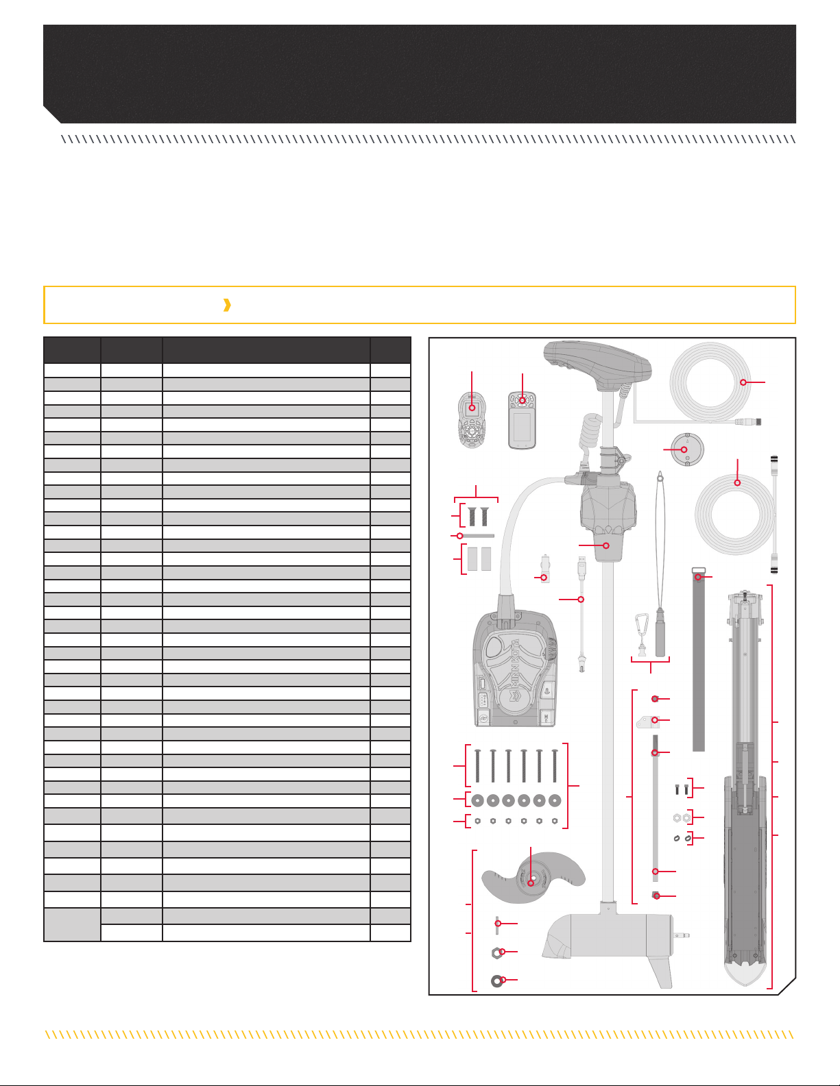
INSTALLING THE ULTREX
Your new Ultrex comes with everything you’ll need to directly install it to the boat. This motor can be directly mounted to the boat or coupled
with a Minn Kota quick release bracket for ease of mounting and removal. For installation with a quick release bracket, refer to the installation
instructions provided with the bracket. For compatible quick release mounting bracket, please visit minnkotamotors.com. To install the motor
directly to the boat, please follow the instructions provided in this manual. Please review the parts list, mounting considerations and tools
needed for installation prior to getting started. For additional product support and to locate your nearest dealer, please visit minnkotamotors.com.
12
3
4
5
6
10
11
13
14
15
12
9
8
7
Item /
Assembly Part # Description Qty.
12994075 tREMOTE ASSEMBLY, IPILOT 1
22994076 ÂREMOTE ASSEMBLY LINK TOUCHSCREEN 1
3✖MOTOR ASSEMBLY 1
A2994887 INSTALLATION HARDWARE BAG ASSEMBLY 1
42263468 1/4 - 20 X 2.5" SS PPH SCREW 6
52263103 1/4 - 20 SS NYLOCK NUT 6
62261713 1/4 FLAT 18-8 SS WASHER 6
AA 1378132 80# THRUST PROP KIT 1
BB 1378160 112# THRUST PROP KIT 1
72341160 PROP-WW2 (4.5)W/ADP.RING 1
82091701 WASHER-PROP (LARGE) 1
92093101 NUT-PROP NYLOC,LG, MX101 3/8 SS 1
10 2262658 PIN-DRIVE 1" 3/16" S/S 1
C2991925 BRACKET STABLZR ARM ASY (SUB) 1
11 22655100 BUMPER STABILIZER 1
12 2263624 STABILIZER ROD 1
13 2263107 NYLON HEX NUT 3/4 - 10 UNC 1
14 2281829 BRACKET 1
15 2260221 VINYL CAP 1
16 2223100 NUT 5/16-18 NYLOCS SS 2
17 2263422 BOLT 5/16-18 X 1" SS CAP SCREW 2
18 2281700 5/16 "ID X .457 OD HIGH COLLAR LOCK WASHER 2
19 2390800 tÂLANYARD, REMOTE W/ CARABEENER 1
20 2773806 STRAP, HOLD DOWN 1
21 2373241 ÂCABLE, USB REMOTE CHARGER LINK 1
22 2375901 ÂADAPTER, USB DC POWER LINK 1
23 2996400 tÂHEADING SENSOR ASSEMBLY 1
24 490389-1 ÂCABLE, ETH (M12-M-M12-F, 30' 1
D2994912 BAG ASSY, FORTREX MOUNT HDW 1
25 2283410 SCREW-1/4-20 X .500" PFH 2
26 2281710 SPACER, GAS SPRING, FORTREX 2
27 2282610 PIN, UPPER SHOCK 1
p2397106 tMANUAL, QUICK REF., iPILOT 1.6 1
p2397107 ÂMANUAL-QUICK REF., iPILOT 3.0 1
p2997161 INSTALLATION GUIDE, ULTREX 1
E2991642 MOUNT ASM ULTREX FW 112# 45" 1
F2991640 MOUNT ASM ULTREX FW 80# 45" 1
G2991641 MOUNT ASM ULTREX FW 80# 52/60" 1
H2991643 MOUNT ASM ULTREX FW 112# 52/60" 1
32 2211415 ÌCABLE-EXTENSION, PD/AP 110" *PRE-INSTALLED* 1
490507-1 âCABLE, ADP-INT MDI 14 M12-120" *PRE-INSTALLED* 1
A
BB
AA
C
E
F
G
H
17
25
16
27
18
26
19
20
21
22
23 24
32
D
INSTALLATION PARTS LIST
pNot shown on Parts Diagram.
✖This part is included in an assembly and cannot be ordered individually.
tOnly available with models factory installed with i-Pilot.
ÂOnly available with models factory installed with i-Pilot Link.
ÌOnly available with models factory installed with Universal Sonar.
âOnly available with models factory installed with Built-in MEGA Down Imaging.
minnkotamotors.com | 9
©2018 Johnson Outdoors Marine Electronics, Inc.
ASSEMBLY OF MOTOR TO MOUNT
• #2 Phillips Screwdriver
• (2) #3 Phillips Screwdriver
• 1/4" Allen Wrench
• Drill
• 9/32" Drill Bit
• 7/16" Box End Wrench
• A person to help with
installation
• Torque Wrench
• File or Sandpaper
• Hack Saw
• Marker or Pencil
• 1/8" Flat Screwdriver
• 1/8" Allen Wrench
• Loctite
a. Place the Mount on an elevated, level surface such
as a workbench or the tailgate of a pickup. The
Mount, as removed from the box, should be in the
deployed position.
b. Remove the 5/16" Allen Screw and Lock Washer
from the Mount using the 1/4" Allen Wrench. The
5/16" Allen Screw is located on the opposite end
of the mount from the hinge that opens and closes
when the mount is stowed and deployed.
It is recommended that the motor be mounted as close to the keel or centerline of the boat
as possible. Make sure the area under the mounting location is clear to drill holes and install
nuts and washers. Make sure the motor rest is positioned far enough beyond the edge of the
boat. The motor must not encounter any obstructions as it is lowered into the water or raised
into the boat when stowed and deployed. Consider a quick release or adapter bracket with the
installation of your motor. To view a list of accessories, please visit minnkotamotors.com.
c. Align the Keyways on the inside of the Steering
Module with the End Links on the Mount. Do this by
positioning the Steering Module above the End Links
on the Mount.
d. Lower the Motor Assembly straight down until the
Steering Module is seated.
Assembly of Motor to Mount
End Links
Keyways
Steering
Module
Allen Screw with
Lock Washer
Mount
Mount
Deployed
Stowed
View accessories
available for your
trolling motor at
minnkotamotors.com.
MOUNTING CONSIDERATIONS
TOOLS AND RESOURCES REQUIRED
INSTALLATION
1
2
WARNING
Carefully lower the Steering Module into place to avoid
creating a pinch point between the Steering Module and
Mount.
10 | minnkotamotors.com ©2018 Johnson Outdoors Marine Electronics, Inc.
INSTALLING THE BOW-MOUNT
e. Reinstall the 5/16" Allen Screw and Lock Washer and
tighten to 18 to 20 ft-lbs with a Torque Wrench.
NOTICE: The 5/16" Allen Screw must be
tightened when installed and periodically
tightened to 18 to 20 ft-lbs. This will allow
the motor to be stowed properly. Tighten the
Allen Screw when the Mount is in the deployed
position.
a. Review the mounting considerations at the beginning
of the Installation section for proper placement.
Place the Mount as close to the centerline or keel of
the boat as possible, with the motor in the stowed
position, on the deck of the boat. Check
placement
with the motor in the stowed and deployed positions.
NOTICE: This motor weighs approximately 55 lbs.
We recommend having a second person help with the
installation.
ITEM(S) NEEDED
#20 x 1
Allen Screw with
Lock Washer
Mount
Deck of Boat
Hold Down Strap
Keel
Mount
b. Place the Hold-Down Strap (Item #20) under the
base of the Mount Plate so that it is below the Mount
when placed.
During installation, it is recommended to mount the motor to the boat before installing the Gas Spring Pin. The Gas Spring Pin is
installed in the Gas Spring Cylinder. The Gas Spring Cylinder is located on the inside of the Outer Arm, which is a part of the Mount.
At this point in the installation, the Gas Spring Cylinder is not fully installed and may move around inside the Mount when stowing and
deploying the motor. The Gas Spring Cylinder can become damaged while deploying the motor and the damage will prevent the Lift-Assist
feature from operating correctly once fully assembled. Make sure that the Gas Spring Cylinder does not get damaged in the Mount.
3
1
Installing the Bow-Mount
CAUTION
The Gas Spring Cylinder can become damaged in the Mount
while stowing or deploying the motor because it is not yet
fully installed. Damage will prevent the Lift-Assist feature
from operating correctly once fully assembled. Make sure
that the Gas Spring Cylinder does not get damaged by
keeping it inside the Outer Arm of the Mount.
minnkotamotors.com | 11
©2018 Johnson Outdoors Marine Electronics, Inc.
INSTALLING THE BOW-MOUNT
Deck of Boat
Hold Down Strap
Keel
Mount
d. Check the placement with the motor in the deployed
position. When the motor is in the deployed position,
make sure that the Shaft is 1-1/2" out past the
Gunwale of the boat. The lower unit, when stowed
and deployed must not encounter any obstructions.
e. Check the placement of the Hold-Down Strap when
the motor is in the stowed and deployed position and
adjust if necessary. 1-1/2"
Minimum
Gunwale
Shaft
c. The Mount can be installed on either the Port
or Starboard side of the boat based on personal
preference. Test the placement of the Hold-Down
Strap to be sure it can hold the Mount as placed.
The placement of the buckle on the Hold-Down
Strap either inboard or outboard is based on personal
preference. The hook and loop on the fastener should
be face down for the Hold-Down Strap to function.
f. Once the Mount is in position, determine which bolt
pattern to use. The bolt pattern selected will depend
on the deck space available on your boat.
g. It is recommended to mark at least 4 of the 6 holes
in the base of the Mount and to have two bolts on
each side that are located the farthest apart on the
Mount Plate. Ideal installation would allow for 6
bolts to be used, with a minimum of 4.
h. Drill through the deck of the boat using a 9/32" Drill
Bit on the marked locations.
i. Be sure the Hold-Down Strap under the base of the
Mount Plate sits between the second and third set
of bolts according to the mounting pattern selected.
Double check that it can close around the Mount
when stowed.
NOTICE: If Pattern 2 is used, the right side plate must
be removed to access the mounting holes in the base of
the Mount.
Pattern 1
Pattern 2
Bow
2
3
4
Hold Down Strap
12 | minnkotamotors.com ©2018 Johnson Outdoors Marine Electronics, Inc.
INSTALLING THE GAS SPRING PIN
j. Put a 1/4-20 x 2 1/2" Screw (Item #4) in each of the
drilled locations. The Screw should pass through the
Mount Plate and the boat deck.
k. Place a Flat Washer (Item #5) and then a Nylock Nut
(Item #6) at the end of each screw as shown and
secure. Make sure all hardware is secure.
ITEM(S) NEEDED
#5 x 6
NOTICE: To prevent seizing of the stainless steel
hardware, do not use high speed installation tools.
Wetting the screws or applying an anti-seize may help
prevent seizing.
Screw
Deck
Flat Washer
and Nylock Nut
a. Position the motor to the stowed position with the
Pull Grip and Cable to disengage the latch bar,
allowing the motor to fold into a flat position.
b. Once in the stowed or flat position, the Gas Spring
Pin and Spacers can be installed.
5
Installing the Gas Spring Pin
1
#6 x 6 #4 x 6
minnkotamotors.com | 13
©2018 Johnson Outdoors Marine Electronics, Inc.
INDEXING THE MOTOR
Deck of Boat
Pedal Control
Sleeve Assembly
Keel
Deck of Boat
Pedal Control
Sleeve Assembly
Control Head
Keel
c. Locate the upper Gas Spring Pin (Item #27) and
Spacers (Item #26) in the bag assembly. Align the end
of the Gas Spring with the holes in the Outer Arm.
d. Install the Gas Spring Pin through the Outer Arm,
then through a Spacer, the end of the Gas Spring
Cylinder and another Spacer.
NOTICE: Spacers are placed on each side of
the Gas Spring on the inside of the Outer Arm.
Phillips Screws have a pre-applied thread locker.
Do not apply additional thread-locker to them as
it may prevent future removal.
ITEM(S) NEEDED
#25 x 2 #26 x 2 #27 x 1
Phillips Screw
Phillips Screw
Phillips Screw
Spacer
Spacer
Spacer
Spacer
Gas Spring Pin
Gas Spring
Cylinder
Gas Spring
Cylinder
Outer Arm
Outer Arm Outer Arm
Outer Arm
Gas Spring
It is recommended to have the Pedal Control Sleeve Assembly pointing inboard. If the Pedal Control Sleeve Assembly points outboard,
please see Orientate the Pedal Control Sleeve Assembly for a Starboard Mount. Use the following instructions to index the motor if the
Pedal Control Sleeve Assembly is already mounted inboard.
Once installed, the system is properly indexed when the motor is deployed and the head of the motor and lower unit align with the
centerline or keel of the boat at the same time the top of the Foot Pedal is parallel to the deck of the boat.
2
Indexing the Motor
Inboard Outboard
e. Install one Phillips Screw (Item #25) on each end
of the Gas Spring Pin and secure with two #3
Phillips screwdrivers.
f. Tighten Phillips Screws until the heads are flush with
the Outer Arm.
14 | minnkotamotors.com ©2018 Johnson Outdoors Marine Electronics, Inc.
INDEXING THE MOTOR
a. Turn the Power Switch "on" and steer the motor so
that the Control Head is in line with the keel of the
boat. This can be done by steering the motor with
the Foot Pedal, turning the motor with the remote, or
manually turning the head of the motor.
b. Leave the Control Head in the desired alignment
and turn the power to the Foot Pedal "off". Then
disconnect the power by removing the power cables
from the battery or turning "off" the breaker if
equipped.
Foot Pedal
Power Switch
Deck of
Boat
Pedal Control
Sleeve Assembly
Control Head
Control Head
Alignment
Keel
c. Remove the Connector Cover from the Wrap
Drum Cover using a 1/8” wide Flat Screwdriver to
release it. Release it by pressing the flat part of the
screwdriver in the slot closest to the center of the
Connector Cover and prying upwards.
d. Once the Connector Cover is removed, disconnect
the Steering Motor Connection Plug that is visible.
NOTICE: Please note the orientation and routing of the
plug and wires for re-installation.
Connector
Cover Wrap Drum
Cover
Wrap Drum
Cover
Connector
Cover
Flat
Screwdriver
Steering Motor Connection Plug
1
2
WARNING
To avoid electric shock, make sure the motor is not
connected to a power source.
2c
2d
minnkotamotors.com | 15
©2018 Johnson Outdoors Marine Electronics, Inc.
INDEXING THE MOTOR
g. Once the Cable Tension Screw is loosened, prying the
Wrap Drum straight up off of the Cable Gear using a
heavy flat-blade screwdriver, until the Wrap Drum is
free of the Cable Gear.
Cable Gear
Flat
Screwdriver
Steering
Cables
Wrap Drum
Cable
Anchor
e. Remove the two screws that hold the Wrap Drum
Cover in place with a #1 Phillips Screwdriver. Once
removed, lift the Wrap Drum Cover away from the
Steering Module.
Steering
Module
Wrap Drum
Cover
Steering Motor
Connection
Plug
Steering Motor
Connection
Plug
Screws
f. The Cable Tension Screw that holds tension on the
Steering Cables is located under the base of the Toe
End of the Foot Pedal. This screw can be loosened
just enough so that the Steering Cables can be
pinched together between the Cable Anchor and
Wrap Drum. Use a #3 Phillips screwdriver to loosen
this screw. Turning the screw approximately 8 turns
counterclockwise should provide enough slack in the
cables to adjust. Keep track of the number of turns
the screw is unscrewed so it can be re-tightened
accordingly later.
NOTICE: The cables are fed through the Cable Anchor
and wound around the Wrap Drum. The right cable is
the shorter cable and begins winding on the Wrap drum
from the top down. The left cable is the longer cable and
begins winding on the Wrap drum from the bottom up.
Cable
Tension
Screw
Toe End of
Foot Pedal
CAUTION
Be careful to not damage the Steering Motor Connection
Plug ends.
3
4
5
CAUTION
Over loosening the Cable Tension Screw may cause the
cables to disengage from the Wrap Drum.
CAUTION
Care must be taken so that the Steering Cables remain on
the Wrap Drum when it is disengaged from the Cable Gear.
It is important that the Steering Cables follow the grooves
on the Wrap Drum so that they do not become intertwined or
pop off. Be sure that the electric wire is not damaged as the
Wrap Drum is lifted.
16 | minnkotamotors.com ©2018 Johnson Outdoors Marine Electronics, Inc.
INDEXING THE MOTOR
Wrap Drum
Steering Motor
Connection Wire
Steering
Cables
Steering
Module
Cable
Anchor
Foot Pedal
h. While holding the Wrap Drum just above the Cable
Gear, and maintaining tension on the Steering
Cables, carefully rotate the Wrap Drum right or left
until the top of the Foot Pedal is parallel with the
deck of the boat. The proper position of the Wrap
Drum will locate the anchors for each of the Steering
Cables equidistant from the mid-line of the Cable
Anchor where it is secured to the Steering Module.
i. Once the Foot Pedal is at the desired position, align
the Wrap Drum with the nearest tooth on the splined
shaft of the Cable Gear. Press the Wrap Drum
securely down so that it is seated on top of the Cable
Gear. At this point, the head of the motor should be
parallel with the keel of the boat and the top of the
foot pedal should be parallel with the deck of the
boat.
Cable
Tension
Screw
Toe End of
Foot Pedal
j. Using a #3 Phillips screwdriver, tighten the Cable
Tension Screw located at the base of the Toe End of
the Foot Pedal to 10 - 12 in-lbs until the Steering
Cables are under tension or re-tighten the same
number of turns as was used in step 4f.
NOTICE: The top of the Wrap Drum has rounded and
smooth edges. The bottom of the Wrap Drum is flat
and the teeth that engage the Cable Gear are visible in
the center.
6
7
CAUTION
Do not make this adjustment by applying pressure to the
Foot Pedal. Rotate the Wrap Drum manually and use the Foot
Pedal position as a guide to indicate the proper position of
the Wrap Drum.
CAUTION
Do not over tighten the Cable Tension Screw, as excessive
tension will cause damage to the unit.
CAUTION
If the Wrap Drum becomes unintentionally disengaged from the
Cable Gear, the Steering Cables can become unwound and will
need to be reassembled correctly for proper operation.

Other manuals for ULTREX

4

Other MINN KOTA Outboard Motor manuals

MINN KOTA ENDURA C2 User manual

MINN KOTA

MINN KOTA ENDURA C2 User manual

MINN KOTA EDGE User manual

MINN KOTA

MINN KOTA EDGE User manual

MINN KOTA TERROVA User manual

MINN KOTA

MINN KOTA TERROVA User manual

MINN KOTA TERROVA User manual

MINN KOTA

MINN KOTA TERROVA User manual

MINN KOTA ENDURA MAX User manual

MINN KOTA

MINN KOTA ENDURA MAX User manual

MINN KOTA FORTEX User manual

MINN KOTA

MINN KOTA FORTEX User manual

MINN KOTA PowerDrive 55 series User manual

MINN KOTA

MINN KOTA PowerDrive 55 series User manual

MINN KOTA ENDURA MAX User manual

MINN KOTA

MINN KOTA ENDURA MAX User manual

MINN KOTA ULTREX User manual

MINN KOTA

MINN KOTA ULTREX User manual

MINN KOTA POWERDRIVE 42 User manual

MINN KOTA

MINN KOTA POWERDRIVE 42 User manual

MINN KOTA PowerDrive User manual

MINN KOTA

MINN KOTA PowerDrive User manual

MINN KOTA POWERDRIVE V2 User manual

MINN KOTA

MINN KOTA POWERDRIVE V2 User manual

MINN KOTA Riptide User manual

MINN KOTA

MINN KOTA Riptide User manual

MINN KOTA MAXXUM Bowmount bowGuard 360 User manual

MINN KOTA

MINN KOTA MAXXUM Bowmount bowGuard 360 User manual

MINN KOTA TALON User manual

MINN KOTA

MINN KOTA TALON User manual

MINN KOTA FORTREX User manual

MINN KOTA

MINN KOTA FORTREX User manual

MINN KOTA Terrova 55 Quick start guide

MINN KOTA

MINN KOTA Terrova 55 Quick start guide

MINN KOTA ULTERRA User manual

MINN KOTA

MINN KOTA ULTERRA User manual

MINN KOTA ENDURA 40 User manual

MINN KOTA

MINN KOTA ENDURA 40 User manual

MINN KOTA Riptide RT User manual

MINN KOTA

MINN KOTA Riptide RT User manual

MINN KOTA Terrova 101 User manual

MINN KOTA

MINN KOTA Terrova 101 User manual

MINN KOTA PowerDrive User manual

MINN KOTA

MINN KOTA PowerDrive User manual

MINN KOTA FORTREX User manual

MINN KOTA

MINN KOTA FORTREX User manual

MINN KOTA Riptide Ulterra User manual

MINN KOTA

MINN KOTA Riptide Ulterra User manual

Popular Outboard Motor manuals by other brands

Torqeedo Cruise 3.0 R/T Translation of the original operating instructions

Torqeedo

Torqeedo Cruise 3.0 R/T Translation of the original operating instructions

Tanaka 945601 - TOB 120 owner's manual

Tanaka

Tanaka 945601 - TOB 120 owner's manual

Mercury Optimax user manual

Mercury

Mercury Optimax user manual

TOHATSU MD 70-90C2 Service manual

TOHATSU

TOHATSU MD 70-90C2 Service manual

Mercury 200 VERADO manual

Mercury

Mercury 200 VERADO manual

Hidea F60 owner's manual

Hidea

Hidea F60 owner's manual

Lewmar 125 VRTT Owners installation, operation & servicing manual

Lewmar

Lewmar 125 VRTT Owners installation, operation & servicing manual

Evinrude 85895 manual

Evinrude

Evinrude 85895 manual

Yamaha F100B owner's manual

Yamaha

Yamaha F100B owner's manual

EMG ELDROclassic Ed 23/5 Assembly instructions

EMG

EMG ELDROclassic Ed 23/5 Assembly instructions

Yamaha F20A owner's manual

Yamaha

Yamaha F20A owner's manual

RHINO BLX 65 BMR owner's manual

RHINO

RHINO BLX 65 BMR owner's manual

Side-Power SE80/185T Installation and user manual

Side-Power

Side-Power SE80/185T Installation and user manual

Yamaha F75D Ower's manual

Yamaha

Yamaha F75D Ower's manual

THUNDER TIGER 5001 - V2 manual

THUNDER TIGER

THUNDER TIGER 5001 - V2 manual

Suzuki DF 25 Service manual

Suzuki

Suzuki DF 25 Service manual

Podkriznik Edyn 1120 instruction manual

Podkriznik

Podkriznik Edyn 1120 instruction manual

SLEIPNER MOTOR AS SIDE-POWER SEP80 installation manual

SLEIPNER MOTOR AS

SLEIPNER MOTOR AS SIDE-POWER SEP80 installation manual

manuals.online logo
manuals.online logoBrands
  • About & Mission
  • Contact us
  • Privacy Policy
  • Terms and Conditions

Copyright 2025 Manuals.Online. All Rights Reserved.