minrray UV500-USB3.0 User manual

HD E-PTZ Video Camera
User Manual
(English)

1
Preface:
Thanks for using our HD color video conference camera.
This manual introduces the function installation and operation of the HD camera. Prior to
installation and usage, please read the manual thoroughly.
Warning
This product can be only used in specified range in order to avoid any damage or danger;
●Don’t expose the camera to rain or moisture place
●Don’t remove the cover to reduce the risk of electric shock. Refer servicing to qualified
personnel.
●Never operate the camera under unqualified temperature , humidity and power supply;
●Please use the soft cloth to clean the camera. Use neuter cleanser if bad smeared .Don’t use
the strong or cleanser avoiding scuffing.
Notes
Electromagnetic fields at the specific frequency may affect the image quality.

2
【Contents】
NOTES...................................................................................... 3
ACCESSORIES............................................................................ 3
FAST INSTALLATION................................................................... 4
CAMERA HIGHLIGHTS..................................................................5
CAMERA SPECIFICATIONS............................................................ 5
CAMERA INTERFACE EXPLANATION................................................6
DIMENSIONS............................................................................. 6
REMOTE CONTROLLER EXPLANATION............................................. 8
RS-232C INTERFACE.................................................................. 10
MENU SETTING......................................................................... 16

3
Notes
Electric Safety
Installation and operation must accord with electric safety standards.
Caution to transport
Avoid stress, vibration and soakage in transport, storage and installation.
Polarity of power supply
The power supply of the product is ±12V; the max electrical current is 2A.
Polarity of the power supply as the following drawing
Install Carefully
Never move the camera by seizing the camera head. Don’t rotate camera head by hand; otherwise,
mechanical trouble will occur.
This series item must put on the smooth desk or platform, and it can not be installed slantways;
If the camera is installed on TV or computer, the base can be fixed by three double-sided adhesive trays.
Don’t apply in corrosive liquid, gas or solid environment to avoid the cover which is made up of organic
material. To make sure no obstacle in rotation range
Never power on before installation is not completed
Don’t dispatch discretionarily
We are not responsible for any unauthorized modification or dismantling.
Accessories
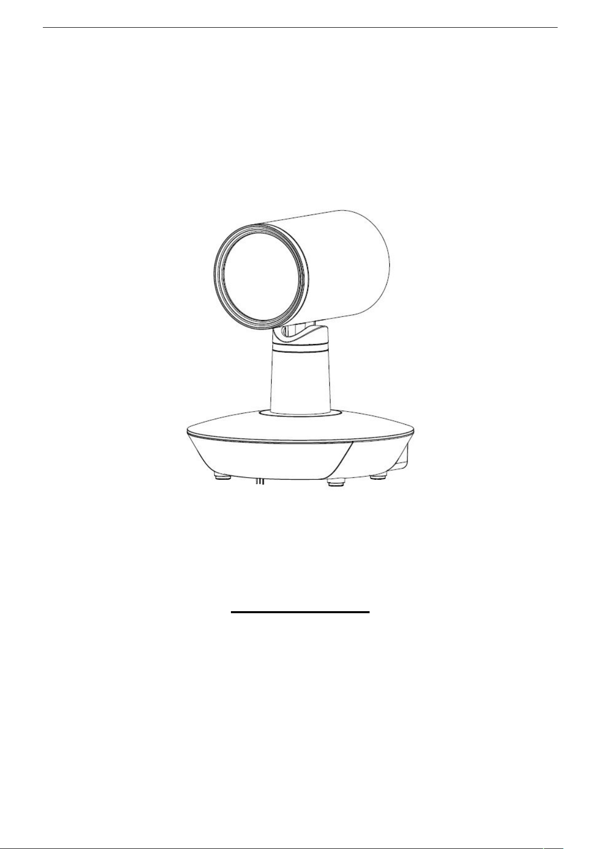
When you open the box, check that all the supplied accessories are included:
Camera.....................................1
Power adapter .........................1
Power cable…………………….1
RS232 cable…………………….1
Remote controller………………1
User manual ……………………1
Double-side glue shim ..............4
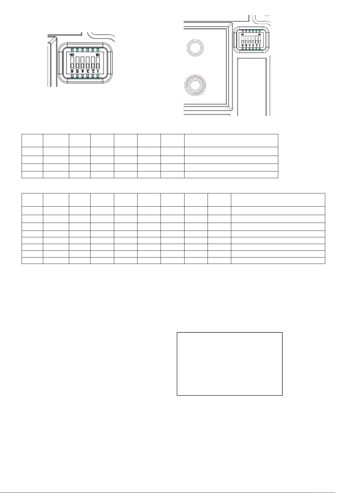
Fast Installation
1、Pls check whether cable connection is correct。

4
UV500-A9-H Model
UV500-A9-U3 Model
2、Dial switch setting at the bottom.
Two DIP switch is set to OFF,ie, choose normal working mode .

5
UV500-A9-H
UV500-A9-U3
3.When the camera is power-on and begin initialize, front panel lights lit in red-yellow-green order cycle, until
the front panel indicator light on to green fixedly, the initiation is completed.(Note: If the power-on mode is
open and saved preset position 0 or 1, then the camera will go to preset 0 or 1 if no operation within 12 secs
after power on)
4、Factory Default : entry OSD menu by pressing the menu key, 【MENU】->
【RESET】->【ALL RESET】, moving the left/right key to select 【Yes】 ,then confirm by 【HOME】。
5.Camera standby:Press the “standby” button on the
remote
controller, the image is closed and the working light will be out, the light flashes once every 20s. If to restart the
self-inspection, pls press “standby” again.
Camera Highlights
1、EPTZ: electronic pan tilt zoom function;
2,Chinese / English menu,convenient to use.;
3、Multi interfaces:USB3.0(UV500-A9-U3) or HD-SDI. HDMI(UV500-A9-H);
4、IR remote controller signal transparent transmission function: camera can receive both its own remote
controller signal and the one from terminal equipment, by transmitting the signal through VISCA IN to
terminal equipment IR receiver.
SW2-2
SW2-
1
SW2-3
SW2-4
SW2-5
SW2-6
Explanation
1
ON
OFF
NC
NC
NC
NC
Undefined
2
OFF
OFF
NC
NC
NC
NC
Updating mode
3
OFF
ON
NC
NC
NC
NC
Debugging mode
4
ON
ON
NC
NC
NC
NC
Working mode
SW2-2
SW2-
1
SW2-3
SW2-4
SW2-5
SW2-6
SW2-7
SW2-8
Explanation
1
ON
OFF
NC
NC
NC
NC
NC
NC
Undefined
2
OFF
OFF
NC
NC
NC
NC
NC
NC
Updating mode
3
OFF
ON
NC
NC
NC
NC
NC
NC
Debugging mode
4
ON
ON
NC
NC
NC
NC
NC
NC
Working mode
5
NC
NC
NC
NC
NC
NC
NC
NC
Undefined
6
NC
NC
NC
NC
NC
NC
NC
NC
Undefined
7
NC
NC
NC
NC
NC
NC
ON
OFF
USB3.0 programming mode
8
NC
NC
NC
NC
NC
NC
OFF
ON
USB3.0working mode
RESET
==============
SYSTEM. RESET NO
CAM.RESET NO
PT. RESET NO
ALL. RESET NO
BACK/MENU

6
Camera Specifications:
video format : 1080P30
Video Output Interface : USB3.0(UV500-A9-U3) or HD-SDI and HDMI(UV500-A9-H)
Image Sensor : SONY IMX117CQT-D
Lens: 2.46 mm ±5%,F2.2±5%, angle of view: 106.2°
Mechanism (Manual Rotation): ±90°for pan rotation, and -25°~+25°for tilt rotation,
support up-side-down installation
Electronic P/T/Z : ±46°for pan rotation, and -25°~+25°for tilt rotation
Presets: 10 preset positions (can reach to128 presets by serial command), precision error less than 0.1°
Support auto/ manual white balance , auto/manual exposure (iris , shuttle )
support WDR function: with performance ≥100dB
Control Signal interface : 8 pins mini DIN--RS232/RS485,VISCA/Pelco-D/Pelco-P protocol
Power interface : HEC3800 power jack , Power supply adapter: DC12V/2A
Max power consumption: 6W
Working temperature: -0℃to +45℃
Storage temperature:-10℃to +60℃
Weight: 1.0KG
Camera Interface Explanation
UV500-A9-H model
1、Camera lens 2、Camera base 3、Working status light indicator
4、Infrared receiver header 5、Tripod screw hole 6、Working mode selection switch
7、Installation hole 8、SDI interface 9、HDMI interface
10、RS232 control interface 11、DC12V Input Power Supply Jack 12、Power light indicator(red)

7
UV500-A9-U3 model
1、Camera lens 2、Camera base 3、Working status light indicator
4、Infrared receiver header 5、Tripod screw hole 6、Working mode selection switch
7、Installation hole 8、USB3.0 interface 9、RS232 control interface
10、DC12V Input Power Supply Jack 11、Power light indicator(red)

8
Dimension:

9
Remote Controller Explanation:
0、Standby key
After pressing the standby key, the camera will step into
standby mode, while the front indicator light is off and
sparks every 20sec.Press again, the camera will do
self-checking again and back to home position.
1. Number key
Setting or locating presets
2.* key
Key combination use
3.Set preset key:
Set preset:
Set preset key + 0-9 number key:
Clear preset key:
Clear preset key + 0-9 number key
or:#+#+#:Clear all the presets
4.BLC control key
BLC function is unavailable
5.Focus control key
Focus+:unavailable
Focus-:unavailable
Auto focus:unavailable
Manual focus:unavailable
6.Camera address selection
Select the camera which wants to be controlled
7. # key
Key combination use
8.pan/tilt control key
Press key :up
Press key :down
Press key :left
Press key:right
“HOME” key: Return to the wide angle position
9.Menu setting
Open or close the OSD menu
10.Zoom Control key
zoom :lens near
zoom :lens far
11.Camera IR remote control address selection
【*】+【#】+【F1】:Camera Address No.1
【*】+【#】+【F2】:Camera Address No. 2
【*】+【#】+【F3】:Camera Address No. 3
【*】+【#】+【F4】:Camera Address No. 4

10
Usage of IR Remote Controller
Finishing initialization, it can receive and execute the IR commands. Users can control the pan/tilt/zoom,
setting and running preset positions via the IR remote controller.
Key Instruction:
1、When a key-combination is required, do it in sequence. For example, “ 【*】+【#】+【F1】”means
press“【*】”first and then press“【#】” and press“【F1】”at last.
1.Pan/Tilt Control
Up: press
Down: press
Left: press
Right: press
Back to wide angle position:press【HOME】
Press and hold the up/down/left/right key, the pan/tilt will keep running, from slow to fast, until it run to the
endpoint; The pan/tilt running stops as soon as the key is released.
2. Zoom Control
ZOOM OUT: press 【ZOOM 】key
ZOOM IN: press 【ZOOM 】key
Press and hold the key, the camera will keep zooming in or zooming out and stops as soon as the key is
released.
3. Focus Control

11
Focus (far):Press 【focus+】key (Valid only in manual focus mode)
Focus (near):Press 【focus-】key (Valid only in manual focus mode)
Auto Focus: unavailable
Manual Focus: unavailable
Press and hold the key, the action of focus continues and stops as soon as the key is released.
4.BLC Setting
BLC ON / OFF : unavailable
5、Presets Setting / Cancel
1、Preset setting : to set a preset position, the users should press the 【SET PRESET】key first and then press
the number key 0-9 to set a relative position, 10 preset positions in total are available.
2、Preset clearing : to clear a preset position, the user can press the 【CLEAR PRESET】key first and then press
the number key 0-9 to clear the relative position;
Note : press the【#】key three times continually to cancel all the presets.
6、Preset Running
Press a number key 0-9 directly to run a relative preset.
Note: Action in vain if a relative preset position does not exist.
7、Camera Selection

12
Select the camera number to control.
8、Camera Remote Controller Address Setting
【*】+【#】+【F1】:Camera Address No.1
【*】+【#】+【F2】:Camera Address No.2
【*】+【#】+【F3】:Camera Address No.3
【*】+【#】+【F4】:Camera Address No.4
RS-232C Interface
Camera Windows DB-9
1.DTR 1.CD
2.DSR 2.RXD
3.TXD1 3.TXD
4.GND 4.DTR
5.RXD1 5.GND
6.GND 6.DSR
7.IR OUT 7.RTS
8.NC 8.CTS
9.RI
Camera Mini DIN
1.DTR 1.DTR
2.DSR 2.DSR
3.TXD 3.TXD
4.GND 4.GND
5.RXD 5.RXD
6.A 6.GND
7.IR OUT 7.NC
8.B 8.NC
Camera RS485
1.DTR
2.DSR
3.TXD1
4.GND
5.RXD1
6.RS485-A A
7.IR OUT
8.RS485-B B
9.GND
No.
Function
1
DTR
2
DSR
3
TXD1
4
GND
5
RXD1
6
RS485-A
7
IR OUT
8
RS485-B

13
COM Control
In normal working mode, the camera is able to be controlled via RS-232C/RS485 command (VISCA IN) . The
parameter of the RS232C/RS485 COM is as following :
Baud Rate :2400/4800/9600/115200 bit/s
Start bit:1bit ;
Data bit: 8bit ;
Stop bit : 1bit;
Code: None
The user can control the camera via serial command only after the camera finished self-check and powered
on..
VISCA PROTOCOL
Part 1 Camera Return Command
Ack/Completion Message
Command Packet
Note
ACK
z0 41 FF
Returned when the command is accepted.
Completion
z0 51 FF
Returned when the command has been executed.
z = Camera Address + 8
Error Messages
Command Packet
Note
Syntax Error
z0 60 02 FF
Returned when the command format is different or when
a command with illegal command parameters is accepted
Command Not Executable
z0 61 41 FF
Returned when a command cannot be executed due to
current conditions. For example, when commands
controlling the focus manually are received during auto
focus.
Part 2 Camera Control Command
Command
Function
Command Packet
Note
AddressSet
Broadcast
88 30 01 FF
Address setting
IF_Clear
Broadcast
88 01 00 01 FF
I/F Clear
CommandCancel
8x 21 FF
CAM_Power
On
8x 01 04 00 02 FF
Power ON/OFF
Off
8x 01 04 00 03 FF
CAM_Dzoom
Stop
8x 01 04 06 00 FF
Stop Dzoom and shift
On
8x 01 04 06 02 FF
Digital zoom ON/OFF
Off
8x 01 04 06 03 FF
Tele (Variable)
8x 01 04 06 2p FF
p=0 (Low) to 7 (High)
* Enabled during Separate Mode
Wide (Variable)
8x 01 04 06 3p FF
x1/Max
8x 01 04 06 10 FF
x1/MAX Magnification Switchover
* Enabled during Separate Mode
Direct
8x 01 04 46 0p 0q 0r 0s FF
pq: D-Zoom Position
* Enabled during Separate Mode
CAM_Initialize
Camera
8x 01 04 19 03 FF
Camera reset
CAM_WB
Auto
8x 01 04 35 00 FF
Normal Auto

14
Command
Function
Command Packet
Note
Manual
8x 01 04 35 05 FF
CAM_RGain
Reset
8x 01 04 03 00 FF
Manual Control of R Gain
Up
8x 01 04 03 02 FF
Down
8x 01 04 03 03 FF
Direct
8x 01 04 43 00 00 0p 0q FF
pq: R Gain
CAM_Bgain
Reset
8x 01 04 04 00 FF
Manual Control of B Gain
Up
8x 01 04 04 02 FF
Down
8x 01 04 04 03 FF
Direct
8x 01 04 44 00 00 0p 0q FF
pq: B Gain
CAM_ColorGain
Direct
8x 01 04 49 00 00 00 0p FF
p: Color Gain setting 0h (60%) to Eh
(200%)
CAM_AE
Full Auto
8x 01 04 39 00 FF
Automatic Exposure mode
Manual
8x 01 04 39 03 FF
Manual Control mode
Bright
8x 01 04 39 0D FF
Bright mode(Manual control)
CAM_Shutter
Reset
8x 01 04 0A 00 FF
Shutter Setting
Up
8x 01 04 0A 02 FF
Down
8x 01 04 0A 03 FF
Direct
8x 01 04 4A 00 00 0p 0q FF
pq: Shutter Position
CAM_Gain
Reset
8x 01 04 0C 00 FF
Gain Setting
Up
8x 01 04 0C 02 FF
Down
8x 01 04 0C 03 FF
Direct
8x 01 04 0C 00 00 0p 0q FF
pq: Gain Positon
CAM_Bright
Reset
8x 01 04 0D 00 FF
Bright Setting
Up
8x 01 04 0D 02 FF
Down
8x 01 04 0D 03 FF
Direct
8x 01 04 4D 00 00 0p 0q FF
pq: Bright l Positon
CAM_ExpComp
On
8x 01 04 3E 02 FF
Exposure Compensation ON/OFF
Off
8x 01 04 3E 03 FF
Reset
8x 01 04 0E 00 FF
Exposure Compensation Amount Setting
Up
8x 01 04 0E 02 FF
Down
8x 01 04 0E 03 FF
Direct
8x 01 04 4E 00 00 0p 0q FF
pq: ExpComp Position
CAM_Aperture
Reset
8x 01 04 02 00 FF
Aperture Control
Up
8x 01 04 02 02 FF
Down
8x 01 04 02 03 FF
Direct
8x 01 04 42 00 00 0p 0q FF
pq: Aperture Gain
CAM_NR
8x 01 04 53 0p FF
p: NR Setting (0: OFF, level 1 to 3)
CAM_NR3D
8x 01 04 54 0p FF
p: NR Setting (0: OFF, level 1 to 5)
CAM_LR_Revers
e
On
8x 01 04 61 02 FF
Image Flip Horizontal ON/OFF
Off
8x 01 04 61 03 FF
CAM_PictureFlip
On
8x 01 04 66 02 FF
Image Flip Vertical ON/OFF
Off
8x 01 04 66 03 FF
CAM_Freeze
On
8x 01 04 62 02 FF
Still Image ON/OFF
Off
8x 01 04 62 03 FF
CAM_PictureEffe
ct
Off
8x 01 04 63 00 FF
Picture Effect Setting
Neg.Art
8x 01 04 63 02 FF
B&W
8x 01 04 63 04 FF
CAM_ICR
On
8x 01 04 01 02 FF
Infrared Mode ON/OFF
Off
8x 01 04 01 03 FF
CAM_Display
On
8x 01 04 15 02 FF
Display ON/OFF
Off
8x 01 04 15 03 FF

15
Command
Function
Command Packet
Note
On/Off
8x 01 04 15 10 FF
CAM_IDWrite
8x 01 04 22 0p 0q 0r 0s FF
pqrs: Camera ID (=0000 to FFFF)
IR_Receive
On
8x 01 06 08 02 FF
IR(remote commander)receive ON/OFF
IR_ReceiveRetur
n
Off
8x 01 06 08 03 FF
IR(remote commander)receive message
via the VISCA communication ON/OFF
On/Off
8x 01 06 08 10 FF
On
8x 01 7D 01 03 00 00 FF
Monitoring Mode
81 01 04 24 72 0p 0p FF
pp:
6,7:1080P30 8:1080P25
14,15: 720P30 17:720P25
E-Zoom Max
8x 01 04 24 52 0p 0p FF
pp: Max D-zoom ratio = 256/ (256-pp)
Cam_Shift
Shift
8x 01 04 7d sh 0h 0h sv 0v 0v
0p FF
s: sign bit,0 is plus, 1 is minus, 2 ignore
the value of this direction
hhh: pan shift view, 0 ~ 1920
vvv: tilt shift view, 0 ~ 1080
p: shift speed, 0x00 ~ 0x0F
Stop
8x 01 04 06 00 FF
Stop Dzoom and shift

16
Part 3 Inquiry command
Command
Command
packets
Return packets
Notes
CAM_PowerInq
8x 09 04 00 FF
y0 50 02 FF
On
y0 50 03 FF
Off(Standby)
CAM_ZoomPosInq
8x 09 04 47 FF
y0 50 0p 0q 0r 0s FF
pqrs: Zoom Position
CAM_FocusModeInq
8x 09 04 38 FF
y0 50 02 FF
Auto Focus
y0 50 03 FF
Manual Focus
CAM_WBModeInq
8x 09 04 35 FF
y0 50 00 FF
Auto
y0 50 05 FF
Manual
CAM_RGainInq
8x 09 04 43 FF
y0 50 00 00 0p 0q FF
pq: R Gain
CAM_BGainInq
8x 09 04 44 FF
y0 50 00 00 0p 0q FF
pq: B Gain
CAM_AEModeInq
8x 09 04 39 FF
y0 50 00 FF
Full Auto
y0 50 03 FF
Manual
y0 50 0D FF
Bright
CAM_ShutterPosInq
8x 09 04 4A FF
y0 50 00 00 0p 0q FF
pq: Shutter Position
CAM_GainPosiInq
8x 09 04 4C FF
y0 50 00 00 0p 0q FF
pq: Gain Position
CAM_ BrightPosiInq
8x 09 04 4D FF
y0 50 00 00 0p 0q FF
pq: Bright Position
CAM_ExpCompModeInq
8x 09 04 3E FF
y0 50 02 FF
On
y0 50 03 FF
Off
CAM_ExpCompPosInq
8x 09 04 4E FF
y0 50 00 00 0p 0q FF
pq: ExpComp Position
CAM_ApertureInq
8x 09 04 42 FF
y0 50 00 00 0p 0q FF
pq: Aperture Gain
CAM_MemoryInq
8x 09 04 3F FF
y0 50pp FF
pp: Memory number last operated.
CAM_LR_ReverseInq
8x 09 04 61 FF
y0 50 02 FF
On
y0 50 03 FF
Off
CAM_PictureFlipInq
8x 09 04 66 FF
y0 50 02 FF
On
y0 50 03 FF
Off
CAM_IDInq
8x 09 04 22 FF
y0 50 0p 0q 0r 0s FF
pqrs: Camera ID
CAM_VersionInq
8x 09 00 02 FF
y0 50 ab cd
mn pq rs tu vw FF
IR_Receive
8x 09 06 08 FF
y0 50 02 FF
On
y0 50 03 FF
Off
IR_ReceiveReturn
y0 07 7D 01 04 00 FF
Power ON/OFF
y0 07 7D 01 04 07 FF
Zoom tele/wide
y0 07 7D 01 04 38 FF
AF On/Off
y0 07 7D 01 04 33 FF
CAM_Backlight
y0 07 7D 01 04 3F FF
CAM_Memory
y0 07 7D 01 06 01 FF
Pan_tiltDrive
Monitoring Mode_Inq
81 09 04 24 72 FF
y0 50 0p 0p FF
pp:
6,7:1080P30 8:1080P25
14,15: 720P30 17:720P25
Pan-tiltPosInq
8x 09 06 12 FF
y0 50 0w 0w 0w 0w
0z 0z 0z 0z FF
wwww: Pan Position
zzzz: Tilt Position
Note:【x】means the camera address you want to control ,【y】=【x + 8】

17
Pelco-D protocol
Function
Byte1
Byte2
Byte3
Byte4
Byte5
Byte6
Byte7
Zoom In
0xFF
Address
0x00
0x20
0x00
0x00
SUM
Zoom Out
0xFF
Address
0x00
0x40
0x00
0x00
SUM
Set Preset
0xFF
Address
0x00
0x03
0x00
Preset ID
SUM
Clear Preset
0xFF
Address
0x00
0x05
0x00
Preset ID
SUM
Call Preset
0xFF
Address
0x00
0x07
0x00
Preset ID
SUM
Query Pan Position
0xFF
Address
0x00
0x51
0x00
0x00
SUM
Query Pan Position
Response
0xFF
Address
0x00
0x59
Value High
Byte
Value Low
Byte
SUM
Query Tilt Position
0xFF
Address
0x00
0x53
0x00
0x00
SUM
Query Tilt Position
Response
0xFF
Address
0x00
0x5B
Value High
Byte
Value Low
Byte
SUM
Query Zoom Position
0xFF
Address
0x00
0x55
0x00
0x00
SUM
Query Zoom Position
Response
0xFF
Address
0x00
0x5D
Value High
Byte
Value Low
Byte
SUM
Pelco-P protocol
Function
Byte1
Byte2
Byte
3
Byte
4
Byte5
Byte6
Byte
7
Byte
8
Zoom In
0xA0
Address
0x00
0x20
0x00
0x00
0xAF
XOR
Zoom Out
0xA0
Address
0x00
0x40
0x00
0x00
0xAF
XOR
Set Preset
0xA0
Address
0x00
0x03
0x00
Preset ID
0xAF
XOR
Clear Preset
0xA0
Address
0x00
0x05
0x00
Preset ID
0xAF
XOR
Call Preset
0xA0
Address
0x00
0x07
0x00
Preset ID
0xAF
XOR
Query Pan Position
0xA0
Address
0x00
0x51
0x00
0x00
0xAF
XOR
Query Pan Position
Response
0xA0
Address
0x00
0x59
Value High
Byte
Value Low
Byte
0xAF
XOR
Query Tilt Position
0xA0
Address
0x00
0x53
0x00
0x00
0xAF
XOR
Query Tilt Position
Response
0xA0
Address
0x00
0x5B
Value High
Byte
Value Low
Byte
0xAF
XOR
Query Zoom Position
0xA0
Address
0x00
0x55
0x00
0x00
0xAF
XOR
Query Zoom Position
Response
0xA0
Address
0x00
0x5D
Value High
Byte
Value Low
Byte
0xAF
XOR

18
MAIN
=================
Language/语言设置 EN
(SYSTEM OPTION)
(CAMERA OPTION)
(PT OPTION)
(V. FORMAT)
(RESET)
(HELP)
EXIT/MENU
Menu setting
1. MENU(main)
In normal working mode, press 【MENU】key to display the menu, using scroll arrow to point at or highlight
the selected items.
Reset state:can be set by users
Language:Chinese / English for options
SYSTEM OPTION:system setting
CAMERA OPTION:camera setting
PT OPTION:pan tilt setting
V. FORMAT: video format setting
RESET:reset setting
HELP:for help
2. SYSTEM OPTION
Move the pointer to the (SYSTEM SET) in the Main Menu, click the【HOME】and enter SYSTEM SET as follow,
SYSTEM SET
=================
PROTOCOL VISCA
ADDR 001
B. RATE 9600
RS485 off
ARMA. VER 1.0
FPGA .VER 1.0
CAM. VER 5F0200
MODEL M500
BACK/MENU
PROTOCOL: Reset State VISCA
Protocol type:VISCA/Pelco-P/Pelco-D
ADDR:Reset State: 001
VISCA=1~7 Pelco-P/Pelco-D = 1~255
B. RATE:Reset State:9600
2400/4800/9600/115200
RS485:Reset State:off
It is ON when using RS485 communication

19
CAMERA SET
=================
(EXPOSURE)
(COLOR)
(NR)
(ZOOM)X3
BACK/MENU
ARM VER./FPGA VER/CAM VER: version information,it will upgrade synchronously with software.
Model: internal identified code
3. CAMERA OPTION
Move the pointer to the (CAMERA SET) in the Main Menu, click the【HOME】and enter CAMERA SET as follows,
EXPOSURE:exposure setting
COLOR: image setting
NR: noise reduction setting
ZOOM: zoom setting
3.1 EXPOSURE
Move the pointer to the (EXPOSURE) in the Main Menu, click the【HOME】and enter EXPOSURE setting as
follows,
EXPOSURE
==================
EXP. MODE Auto
SHUTTER --
GAIN --
BRIGHT --
EV. MODE off
LEVEL --
BACK/MENU
EXP. MODE:Reset State: Auto
Available mode: Auto,Manual,Bright
SHUTTER:Reset State: Default
Available selections: 1/30、1/60、1/90、1/100、1/125、1/180、1/250、1/350、1/500、
1/725、1/1000、
1/1500、1/2000、1/3000、1/4000、1/10000(only available in Manual Shutter mode)
GAIN: Reset State: Default
Available: 0~15(only available in Manual mode)
BRIGHT:Reset State: 3
Available: 0~9 (only available in Bright mode)
EV MODE:Reset State: off
Available: On/Off (only available in Auto Exposure mode)
LEVEL:Reset State: Default
Available Setting: -6~6
Table of contents
Other minrray Security Camera manuals