manuals.online logo
Brands
  1. Home
  2. •
  3. Brands
  4. •
  5. Minuteman
  6. •
  7. UPS
  8. •
  9. Minuteman ERS1500RTNC User manual

Minuteman ERS1500RTNC User manual

Other Minuteman UPS manuals

Minuteman Smart Up Series User manual

Minuteman

Minuteman Smart Up Series User manual

Minuteman CPE 1000 On-Line Series Instructions for use

Minuteman

Minuteman CPE 1000 On-Line Series Instructions for use

Minuteman PRO1100E User manual

Minuteman

Minuteman PRO1100E User manual

Minuteman MCP 1000 User manual

Minuteman

Minuteman MCP 1000 User manual

Minuteman Pro Series User manual

Minuteman

Minuteman Pro Series User manual

Minuteman Enterprise Plus Series User manual

Minuteman

Minuteman Enterprise Plus Series User manual

Minuteman EN750LCD User manual

Minuteman

Minuteman EN750LCD User manual

Minuteman AT1200 User manual

Minuteman

Minuteman AT1200 User manual

Minuteman 1000 VA User manual

Minuteman

Minuteman 1000 VA User manual

Minuteman AT300 User manual

Minuteman

Minuteman AT300 User manual

Minuteman Enterprise Plus LCD RTXL UPS Series User manual

Minuteman

Minuteman Enterprise Plus LCD RTXL UPS Series User manual

Minuteman MBK 300YYY User manual

Minuteman

Minuteman MBK 300YYY User manual

Minuteman ED6000RMXFMR User manual

Minuteman

Minuteman ED6000RMXFMR User manual

Minuteman Continuous Power MCP 10001 User manual

Minuteman

Minuteman Continuous Power MCP 10001 User manual

Minuteman CPE 1000 User manual

Minuteman

Minuteman CPE 1000 User manual

Minuteman E750RM2U User manual

Minuteman

Minuteman E750RM2U User manual

Minuteman PRO1500RT User manual

Minuteman

Minuteman PRO1500RT User manual

Minuteman Endeavor RTXL Series User manual

Minuteman

Minuteman Endeavor RTXL Series User manual

Minuteman PARASHIELD 1224 User manual

Minuteman

Minuteman PARASHIELD 1224 User manual

Minuteman SentryII UPS User manual

Minuteman

Minuteman SentryII UPS User manual

Minuteman EN350 User manual

Minuteman

Minuteman EN350 User manual

Minuteman Continuous Power Series User manual

Minuteman

Minuteman Continuous Power Series User manual

Minuteman Encompass EC1000RT2U User manual

Minuteman

Minuteman Encompass EC1000RT2U User manual

Minuteman MBK Series User manual

Minuteman

Minuteman MBK Series User manual

Popular UPS manuals by other brands

AEG Protect 3.M 2.0 manual

AEG

AEG Protect 3.M 2.0 manual

Alpha Novus FXM 650 Installation and operation manual

Alpha

Alpha Novus FXM 650 Installation and operation manual

CyberPower RB12120X2A user manual

CyberPower

CyberPower RB12120X2A user manual

Pylontech Victron & Pylontech US5000 manual

Pylontech

Pylontech Victron & Pylontech US5000 manual

BEL LDX-U20 user manual

BEL

BEL LDX-U20 user manual

Mustek PowerMust 530(B) Plus Startup manual

Mustek

Mustek PowerMust 530(B) Plus Startup manual

Emerson Liebert NXL series Operation and maintenance manual

Emerson

Emerson Liebert NXL series Operation and maintenance manual

MAKELSAN BOXER SERIES user manual

MAKELSAN

MAKELSAN BOXER SERIES user manual

Block PC-0524-400-0 manual

Block

Block PC-0524-400-0 manual

CyberPower CP585LCD user manual

CyberPower

CyberPower CP585LCD user manual

Eaton 3S Advanced user's guide

Eaton

Eaton 3S Advanced user's guide

CyberPower Office Tower Series UPS 1000 user manual

CyberPower

CyberPower Office Tower Series UPS 1000 user manual

CyberPower BM100 quick start guide

CyberPower

CyberPower BM100 quick start guide

Best Power 610 quick start guide

Best Power

Best Power 610 quick start guide

Best Power Unity/I UT3K user manual

Best Power

Best Power Unity/I UT3K user manual

Mustek PowerMust 400 Offline user manual

Mustek

Mustek PowerMust 400 Offline user manual

Xantrex Trace 512 UR-UPS owner's manual

Xantrex

Xantrex Trace 512 UR-UPS owner's manual

Forza SL-1501UL user manual

Forza

Forza SL-1501UL user manual

manuals.online logo
manuals.online logoBrands
  • About & Mission
  • Contact us
  • Privacy Policy
  • Terms and Conditions

Copyright 2025 Manuals.Online. All Rights Reserved.

User's Manual
ERS1500RTNC
Series UPS
Para Systems, Inc.
1455 LeMay Dr.
Carrollton, TX 75007
Phone: 1-972-446-7363
Fax: 1-972-446-9011
Internet: minutemanups.com
UPS Sizing: sizemyups.com
PN - 34000438 R2
1
1. Introduction 2
2. Controls and Indicators 6
3. Installation 7
4. Operation 13
5. Troubleshooting 16
6. Replacing the Battery 17
7. Obtaining Service 21
8. Specifications 22
9. Limited Product Warranty 24
A1. Declaration of Conformity 25
3
2
WARNING: Risk of Electrical Shock. Hazardous live parts inside these
power supplies are energized from the battery even when the AC input is
disconnected.
CAUTION! To de-energize the outputs of the UPS:
1. If the UPS is on press and release the On/Off/Test Button.
2. Disconnect the UPS from theAC wall outlet.
3. To de-energize the UPS completely, disconnect the battery.
CAUTION! To reduce the risk of electrical shock in conditions where the
load equipment grounding cannot be verified, disconnect the UPS from the
AC wall outlet before installing a computer interface cable. Reconnect the
power cord only after all signaling connections are made.
CAUTION! Connect the UPS to a two pole, three wire grounding AC wall
outlet. The receptacle must be connected to the appropriate branch protec-
tion (circuit breaker or fuse). Connection to any other type of receptacle may
result in a shock hazard and violate local electrical codes. Do not use exten-
sion cords, adapter plugs, or surge strips.
CAUTION! Toreduce the risk ofelectricalshock with theinstallationof this
UPS equipment and the connected equipment, the user must ensure that the
combined sum of theAC leakage current does not exceed 3.5mA.
WARNING: ThisUninterruptible Power Supplycontains potentiallyhazard-
ous voltages. Do not attempt to disassemble the UPS beyond the battery
replacement procedure. This UPS contains no user serviceable parts. Re-
pairs and Battery replacement must be performed by QUALIFIED SERVICE
PERSONNELONLY.
CAUTION! To reduce the risk of fire, connect only to a circuit provided with
20 amperes maximum branch circuit over-current protection in accordance
with the National Electric Code,ANSI/NFPA70.
IMPORTANT SAFETY INSTRUCTIONS
CONSIGNES DE SÉCURITÉ IMPORTANTES
SAVE THESE INSTRUCTIONS !
SAUVEGARDEZ CES CONSIGNES!
Thankyoufor purchasingthispower protectionproduct. Ithas beendesigned
andmanufactured toprovidemany yearsof troublefreeservice.
Pleaseread this manualbefore installingyourUPS, modelERS1500RTNCas
itprovides importantinformationthat shouldbe followedduring installationand
maintenance of the UPS and batteries allowing you to correctly set up your
system for the maximum safety and performance.
Veuillezlirecemanuelavant l'installationdel'onduleurmodèleERS1500RTNC.
Il contient de l'information importante qui doit être respectée au cours de
l'installation et de l'entretien de l'onduleur et des batteries. Cette information
vous permettra de correctement installer le système pour atteindre son
rendementmaximum en toutesécurité.
Included is information on customer support and factory service if it is re-
quired. If you experience a problem with the UPS please refer to theTrouble-
shooting guide in this manual to correct the problem or collect enough infor-
mation so that the Technical Support Department can rapidly assist you.
CAUTION! DO NOT USE THE MOUNTING BRACKETS TO LIFT THE
UPS. The mounting brackets are ONLYfor securing the UPS to the rack.
CAUTION! This UPS is intended to be installed in a temperature/humidity
controlledenvironmentthat is freeof conductive contaminants.
ATTENTION! Cet onduleur est conçu pour installation dans un milieu à
températureethumidité contrôlées, librede contaminants conducteurs.
This UPS series is not intended for use in a computer room as defined in the
Standard for the Protection of Electronic Computer/Data Processing Equip-
mentANSI/NFPA75.
CAUTION! The Maximum ambient operating temperature for this UPS se-
ries is 50°C (“-15 ~ +50°C” for Ambient Operation).
NOTICE! The output of this device is not sinusoidal. It has a total harmonic
distortionandmaximum singleharmonicas below:
Total harmonic42.8% Single harmonic 26.6%
5
4
Life Support Policy
Asageneral policy, wedonot recommendtheuse ofany of ourproducts inlife
supportapplications wherefailureor malfunctionof theproductcan bereason-
ablyexpectedto causefailure ofthelife supportdeviceor tosignificantly affect
its safety or effectiveness. We do not recommend the use of any of our prod-
ucts in direct patient care. We will not knowingly sell our products for use in
such applications unless it receives in writing assurances satisfactory to us
that (a) the risks of injury or damage have been minimized, (b) the customer
assumes all such risks, and (c) our liability is adequately protected under the
circumstances.
Examplesof devicesconsidered tobelifesupportdevicesareneonataloxygen
analyzers,nervestimulators (whetherused for anesthesia,pain relief,orother
purposes), auto transfusion devices, blood pumps, defibrillators, arrhythmia
detectorsandalarms, pacemakers,hemodialysissystems, peritonealdialysis
systems,neonatalventilator incubators,ventilators for bothadults andinfants,
anesthesiaventilators, and infusionpumps aswellas anyother devicesdesig-
nated as “critical” by the United States FDA. These UPSs do not meet the
requirements for use in direct patient care.
After removing your UPS from its carton, it should be inspected for damage that
may have occurred in shipping. Immediately notify the carrier and place of pur-
chase if any damage is found. Warranty claims for damage caused by the carrier
willnot behonored. The packingmaterials that yourUPS wasshipped inare care-
fullydesigned tominimize anyshipping damage. Inthe unlikelycase that theUPS
needsto bereturned tothemanufacturer,please usethe originalpacking material.
Sincethe manufacturer is not responsiblefor shippingdamage incurredwhen the
systemisreturned, theoriginalpackingmaterial isinexpensiveinsurance. PLEASE
SAVE THE PACKING MATERIALS!
Receiving Inspection
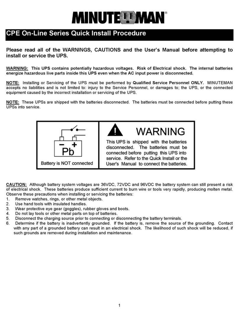
NOTE: These UPSs are shipped with the batteries disconnected. The batteries
must be connected before putting these UPSs into service. Refer to Section 3
"Installation"for connectingthe batteries.
NOTICE: This equipment has been tested and found to comply with the limits for
a Class B computing device in accordance with the specifications in Subpart J of
Part 15 of FCC Rules and the Class B limits for radio noise emissions from digital
apparatus set out in the Radio Interference of the Canadian Department of Com-
munications. These limits are designed to provide reasonable protection against
suchinterference ina residentialinstallation. This equipmentgenerates anduses
radio frequency and if not installed and used properly, that is, in strict accordance
withthe manufacturer'sinstructions, this equipment may causeinterference tora-
dio and television reception. If this equipment does cause interference to radio or
televisionreception, whichcan bedeterminedby turningthe equipmentoff andon,
theuser isencouragedto trytocorrect the interferencebyone ormoreof thefollow-
ingmeasures:
Reorientthe receivingantenna.
Relocatethe computerwith respectto thereceiver.
Movethe computeraway fromthe receiver.
Plugthe computerinto adifferent outletso thatthe computerand receiver
areon differentbranch circuits.
Shieldedcommunications interface cables must beused withthis product.
WARNING: Changes or modifications to this unit not expressly approved by the
partyresponsiblefor compliancecouldvoidthe user'sauthority tooperatetheequip-
ment.
ON / OFF / TEST BUTTON: Toturn theUPSon: pressand holdtheOn/Off/
TestButton untilthealarm soundsonebeep andthenrelease. The UPSwill
perform a five second self-test. Once the UPS has passed its self-test the
UPS will provide an output and the load will be powered. To turn the UPS
off: pressand holdthe On/Off/Test Buttonuntil thealarm soundsone beep
andthen release. To performaten-second batterytest: With theUPSin the
ACmode, pressandhold theOn/Off/TestButton untilthe alarm soundsfour
beeps,and thenrelease. During thetest, theUPS willswitch tothe Battery
mode,the On-Batteryicon willilluminate andthe alarmwill sound.
© COPYRIGHT 2014 BY PARA SYSTEMS, INC.
AllRightsReserved.All rightsof thisUser Manual(“Manual”),including butnot
limited to the content, information, and figures are solely owned and reserved
by Para Systems, Inc. (“Para Systems”). The Manual can only be applied to
the operation or the use of this product.Any disposition, duplication, dissemi-
nation, reproduction, modification, translation, extraction, or usage of this
Manual in whole or in part is prohibited without the prior written permission of
ParaSystems. Giventhat ParaSystemswillcontinuouslyimproveanddevelop
the product, changes may be made to the information in this Manual at any
time without obligation to notify any person of such revision or changes. Para
Systems will make all possible efforts to secure the accuracy and the integrity
of this Manual. Para Systems disclaims any kinds or forms of warranty, guar-
antee,orundertaking, eitherexpresslyor implicitly, including butnotlimited to
thecompleteness,faultlessness, accuracy, non-infringement, merchantability
or fitness for a particular purpose of the Manual.
7
6
INSTALLATION PLACEMENT
Output Power Receptacles
NEMA5-15P
W/10 ft cord
Model # Input Power Plug
ERS1500RTNC 6-NEMA 5-15R Battery Backup & Surge
2-NEMA 5-15R Surge Only
REAR PANEL
1. RS232 Communications Port is for UPS monitoring and control.
2. USB Communications Port is for UPS monitoring and control.
3. TheRJ11/45 areused forphone/fax/modemand networkprotection.
4. SNMP Card is for UPS monitoring and control (Included).
5. Battery Backup & Surge output receptacles for mission critical equipment.
6. Surge ONLY output receptacles for noncritical equipment.
7. Input power cord is for connecting to the Utility Power.
8. Inputcircuitbreaker is forprotection against anexcessiveoverload.
ThisUPSis intendedtobe installedina temperature/humidity controlledenvi-
ronmentthatis freeof conductive contaminants. DONOT operatetheUPS in:
extremely dusty and/or unclean areas, locations near heating devices, water
or excessive humidity, or where the UPS is exposed to direct sunlight. Select
a location, which will provide good air circulation for the UPS at all times.
Route power cords so they cannot be walked on or damaged. Typical battery
lifeis2 to 3 years. Environmentalfactorsdo affect battery life. Hightempera-
tures,poorutility power, andfrequent,short durationdischargeshave a nega-
tive impact on battery life.
CONTROL PANEL
1. AC normal and Boost/Buck mode LED (Green): Illuminates when the UPS
is in theAC normal mode and flashs when the UPS is in the Boost or the
Buck mode.
2. Battery mode LED (Yellow): Illuminates when the UPS is operating in the
Battery mode.
3. Fault LED (Red): Illuminates when the UPS has detected an internal fault.
4. On/Off/Test Button: To turn the UPS On/Off and to perform a ten-second
battery test.
CAUTION! DO NOT USE THE MOUNTING BRACKETS TO LIFT THE
UPS. The mounting brackets are ONLYfor securing the UPS to the rack.
9
8
RACKMOUNTCONFIGURATION
This UPS comes with mounting brackets for the standard 19" (46.5cm) rack.
The mounting brackets to fit a 23" (59.2cm) standard rack are also available.
The screws for mounting the UPS to the rack are not included (screw size
varies with rack size).
1. Locate the mounting bracket screw holes on the side panels of the UPS, at
the front of the UPS. NOTE: The mounting brackets can also be mounted
in the middle of the UPS.
2. Align the mounting bracket with the mounting bracket screw holes.
3. Attach the mounting bracket with the retaining screws.
CAUTION: Do not use the mounting brackets to lift the UPS. The mounting
brackets are ONLYfor securing the UPS to the rack.
4. Mount the UPS into the rack and secure with the retaining screws.
WARNING: Use two ormore peoplewheninstallingtheUPS. Use CAUTION,
the UPS is extremely heavy. Do not move the rack after the units have been
installed. The rack may be unstable due to the weight distribution.
5. TheRackmount Configurationis complete.See Connectingyour Equipment
CONNECTING THE BATTERIES
(QUALIFIEDSERVICEPERSONNELONLY)
Please read all of the WARNINGS and CAUTIONS before attempting to con-
nect the batteries.
1. RemovetheUPS from theshipping box andseton theflooror a benchtop.
2. Removethefront panelretainingscrews.
3. Lay the front panel on top of the UPS.
4. Verify proper polarity. Connect the battery connectors (red and black) to-
gether.
NOTE: Some sparking might occur, this is normal.
5. Re-install the front panel onto the UPS.
6. Reinstall the front panel retaining screws.
7. Continue with the rest of the Installation.
INSTALLATION
Besureto readtheinstallation placementand all thecautions before installing
the UPS. Place the UPS in the final desired location and complete the rest of
theinstallationprocedure. These UPSsareshipped withthe internal batteries
disconnected. The batteries must be connected before putting these UPSs
intoservice. Seethe ConnectingThe Batteriesprocedure toconnect thebatter-
ies.
TOWER CONFIGURATION
The tower configuration allows the user to install the UPS in the upright posi-
tionnext tothetowercomputer. Thetowerbracketsareprovided withtheUPS.
WARNING: Use two ormore peoplewheninstalling theUPS. Use CAUTION,
the UPS is extremely heavy.
1. Once the location of the UPS has been determined, place the tower brack-
ets in the desired location.
WARNING: The UPS must be installed in the proper upright position. If the
UPS is not installed in the proper upright position the Batteries will be dam-
aged. Once the UPS is placed in the tower position, looking at the front panel
theYELLOW Batterydisconnectedlabel onthe topcoverof theUPS MUSTbe
on your left hand side.
11
10
4. Use the template to mark the screw hole position on the wall. CAUTION,
you should always were protective gear for your hands and eyes when
operating power tools.
5. Attach the four retaining screws to the wall and make sure that all of the
retaining screws are screwed into structural material. Then clean the area
ofanyloose material. Do nottighten the retainingscrews all theway,leave
approximately 3/8" of the retaining screws sticking out.
6. PositiontheUPS, sothatthe mountingbracketkeyed holes lineup with the
four retaining screws. Slide the UPS down until its resting securely on the
four retaining screws.
7. Tighten the four retaining screws to secure the UPS to the wall.
8. TheWallmount Configurationis complete.SeeConnectingyourEquipment.
2. The LED face plate can be rotated to read in the upright position. Remove
the front panel from the UPS. On the backside of the front panel, push the
LED face plate outwards the face plate will pop out. Position the LED face
plate so that it reads in the upright position. Reinstall the front panel on
the UPS.
3. Thetworackmount brackets are usedforthe two towerbrackets. Remove
the retaining screws and attached the tower brackets as shown. The tower
brackets go on both sides of the UPS. Make sure that the UPS is stable.
4. TheTowerConfigurationis complete. See ConnectingyourEquipment.
WALLMOUNT CONFIGURATION
The wallmount configuration allows the user to mount the UPS on the wall.
Thereis awallmount bracketkitavailablefortheUPS. Thekitincludestwo wall
mountingbrackets, tenretaining screws,andthe wallmounttemplate. WARN-
ING: Use two or more people when installing the UPS. Use CAUTION, the
UPSis extremely heavy. TheUPS's sidepanels havemountingbracket screw
holes for attaching the wall mounting brackets.
1. Once the location and position of the UPS has been determined, lay the
UPS down flat.
WARNING: The UPS must be installed in the proper upright position. If the
UPS is not installed in the proper upright position the Batteries will be dam-
aged. Once the UPS is placed on the wall, looking at the front panel the
YELLOWBatterydisconnected labelonthe topcover of theUPS MUST beon
yourlefthand side.
2. Align the mounting brackets with the mounting bracket screw holes and
attach with the six retaining screws.
3. The LED face plate can be rotated to read in the upright position. Remove
the front panel from the UPS. On the backside of the front panel, push the
LED face plate outwards the face plate will pop out. Position the LED face
plate so that it reads in the upright position. Reinstall the front panel on
the UPS.
CONNECTING YOUR EQUIPMENT
Plug the mission critical equipment into the Battery Backup & Surge output
receptacles on the rear panel of the UPS. Plug the noncritical equipment into
the Surge Only output receptacles on the rear panel of the UPS. Ensure that
the connected equipment does not exceed the maximum output rating of the
UPS(refer totheinformation labelon theUPSor theelectrical specificationsin
thismanual). DONOTPLUGEXTENSIONCORDS,ADAPTERPLUGS,SURGE
STRIPS OR POWER STRIPS INTOTHE OUTPUT RECEPTACLES OFTHE
UPS. NOTE: Risk of damaging the UPS and/or connected equipment.
CAUTION! DO NOT connect a laser printer to the output of the UPS.
13
12
NETWORK/PHONE/FAX/MODEM PROTECTION CONNECTION (OPTIONAL)
Connect a 10/100 Base-T network, single line phone, Fax or Modem line to the
RJ11/45 modular connectors on the rear panel of the UPS. This connection will
require another length of telephone or network cable. The cable coming from
the telephone service or networked system is connected to the port marked
“IN”. The equipment to be protected is connected to the port marked "OUT".
NOTE: Connecting to the Network/Phone/Fax/Modem modular connectors is
optional. The UPS works properly without this connection.
COMMUNICATIONS PORT CONNECTION (OPTIONAL)
The power monitoring software and interface cables can be used with the UPS.
Connect the interface cable (Serial or USB) to the appropriate communications
porton therear panelof theUPS. Connect theother end ofthe cableto thedevice
that will be monitoring/controlling the UPS. NOTE: The SNMP card must be re-
moved before using the Serial or USB Communications ports. Connecting to the
CommunicationsPort isoptional. TheUPS worksproperlywithout thisconnection.
CAUTION! The TNV connector shall use the same type of RJ45.
CONNECTING THE UPS TO AN AC SOURCE
CAUTION - To reduce the risk of fire, connect only to a circuit provided with 20
amperes maximum branch circuit over-current protection in accordance with
the National Electric Code, ANSI/NFPA 70. Plug the UPS into a two pole, three
wire, grounded receptacle only. DO NOT PLUG THE UPS INTO EXTENSION
CORDS, ADAPTER PLUGS, SURGE STRIPS OR POWER STRIPS. DO NOT
CUT THE INPUT PLUG OFF AND ATTEMPT TO HARDWIRE THIS UPS, DO-
ING SO WILL VOID THE WARRANTY.
CHARGING THE BATTERY
The UPS will charge the internal batteries whenever the UPS is connected to
an AC source and there is an acceptable AC voltage present (90 - 150VAC). It
is recommended that the UPS's batteries be charged for a minimum of 4 hours
before use. The UPS may be used immediately, however, the “On Battery”
runtime may be less than normally expected. Typical battery life is 2 to 3 years.
Environmentalfactors doaffect battery life. High temperatures,poor utilitypower,
andfrequent,short durationdischargeshave anegative impactonbattery life. This
UPShas atemperature compensatingcharger. Asthe ambienttemperature rises
the charger will reduce the voltage to prevent premature failures of the batteries.
NOTE: If the UPS is going to be out of service or stored for a prolonged period of
time, the batteries must be recharged for at least twenty-four hours every ninety
days.
SNMP CARD
Theincluded SNMP Cardis webbasedand isusedfor monitoringand control-
lingtheUPS. See the SNMPCard's Manual forconfiguring and settingupthe
SNMPCard. NOTE: Connectingto theSNMP Cardis optional. TheUPS works
properlywithout thisconnection.
SYSTEM OVERVIEW
This Line-Interactive UPS protects computers, servers, telecom systems, VoIP sys-
tems, security systems, and a variety of electronic equipment from blackouts, brown-
outs, overvoltages, and surges. The AVR function continuously corrects the voltages,
in-betweenthebrownoutand overvoltagetransfer points(90 - 150VAC),toa safe usable
level. When the UPS is operating in the AVR mode the audible alarm will remain silent
andtheAC normalmode indicator willblink. During normalAC operation,the UPSwill
quietlyand confidently protectyoursystem frompower anomalies.
TheUPS will chargethe batterieswiththe UPS inthe onoroff position whenthe UPSis
pluggedintothewall outlet and there isan acceptableACvoltagepresent(90- 150VAC).
ThisUPS has atemperature compensating charger. Astheambient temperature rises
thecharger will reducethe voltagetoprevent premature failuresofthe batteries. When
a blackout, brownout, or an overvoltage condition occurs; the UPS will transfer to the
battery mode, the Battery mode LED will illuminate and the audible alarm will sound
once every five seconds indicating that the commercial power is lost or unacceptable.
Whenthe commercial powerreturnsor is atanacceptable level, theUPSwill automati-
callytransfer back totheACnormalmode and startrecharging the batteries. Duringan
extendedoutagewhen there is approximatelytwo minutesof backuptime remaining the
audiblealarm will soundtwice every fiveseconds. ThisLow Battery Warning is inform-
ing the user that they should save all open files and turn off their computer. When the
batteriesreach the predeterminedlevel theUPSwill automatically shutdownprotecting
the batteries from over discharging. Once the commercial power returns the UPS will
automaticallyrestart,providing safe usablepower tothe connectedequipment andstart
rechargingthe batteries.
TURNING THE UPS ON / OFF
To turn the UPS on: press and hold the On/Off/Test Button until the alarm sounds one
beepand then release. TheUPSwill perform afivesecond internal self-test. Oncethe
UPShas passed itsinternalself-test the UPSwillprovide an outputandthe loadwill be
powered. To turn the UPS off: press and hold the On/Off/Test Button until the alarm
soundsone beep andthenrelease.
Block Diagram of the Basic Wiring and Internal Circuit Configuration
15
14
USBCOMMUNICATIONSPORT
This UPS supports USB communications. The USB communications protocol is HID.
The HID USB driver comes standard in the Windows OS. Simply plug the USB cable
intothe UPSandthe computerthenfollow theprompts on thescreen.
SNMP CARD
Theincluded SNMP Cardis webbasedand isusedfor monitoringand control-
lingtheUPS. See the SNMPCard's Manual forconfiguring and settingupthe
SNMPCard.
LED Function
TheUPS provides bothvisual andaudibleindicators. There are threevisualindicators:
anAC mode GreenLED,a BatterymodeYellow LEDand a Faultcondition Red LED. ALARMS
ONBATTERY
Whenthe UPSisoperating on thebatteries, theACmode LED willextinguish, the Bat-
tery mode LED will illuminate and the alarm will sound one beep every five seconds.
OncetheUPS returns to thenormalAC mode, the alarmwill stop,the Batterymode LED
willextinguish and theACmodeLED will illuminate.
WEAK/BADBATTERY
The UPS automatically tests the battery’s condition. If the battery is weak, bad or
disconnected, the Fault LED will flash and the alarm will sound three beeps every five
minutesuntil thebattery iseither reconnected orreplaced. This alarm willbe repeated
untilthebatteries pass aself-test. It isrecommended thatthe UPSbe allowedto charge
overnightbefore performing abatterytest to confirma Weak/Bad Batterycondition.
OVERLOAD
When the amount of load attached to the UPS exceeds its power rating, the Fault LED
will illuminate and the alarm will sound continuously (AC and Battery modes). This
alarmwill remain onuntilthe excess loadisremoved or theUPS’sself protection circuit
shutsthe UPSdown. Toclear the overload alarmwhentheUPS has shutdownrequires
thatthe UPS performa batterytest. Firstremove part oftheload, then turnthe UPSon,
theFault LED andthealarm will beon. Second eitherusetheTest Button orunplugthe
inputpower cordto performthe battery test.
LOWBATTERYWARNING
When the batteries reach the predetermined level, the alarm will sound two beeps
everyfiveseconds and the Batterymode LEDwill flash. This conditionwill continueuntil
eitherAC returns orthe UPS’sself protectioncircuit shutsthe UPSdown toprotect the
batteryfrom over discharging.
UPSFAULT
When the UPS detects an internal fault, the Fault LED will illuminate, the alarm will
sound continuously and the output will be turned off. The fault condition, in some in-
stances,may be resetby turningtheUPS off and thenon. Ifthe fault conditiondoes not
clear the UPS must be sent in for service.
BATTERYOVERCHARGEPROTECTION
If the charger is providing too much voltage to the battery the UPS will turn off the
charger to protect the battery. When the charger voltage exceeds 45V the charger will
turn off. The alarm will sound three beeps every five seconds and the Fault LED will
flashandthe alarm willsound three beepsevery 5-seconds. TheUPS willautomatically
transfer to the battery mode and operate until the UPS shuts down due to battery ex-
haustion. Insome instances, thechargermay bereset byturning the UPSoffand then
on. If the charger does not rest then the UPS must be sent in for service.
RS232COMMUNICATIONSPORT
The power monitoring software and interface cables can be used with the UPS. The
RS232 communication port is a standard DB9 female with both RS232 and simulated
contactclosure capability. The pinoutforthe portis depicted perthe chart below:
Pin1: Simulatedcontactclosure Low BatteryWarning, NO
Pin2: /TXD
Pin 3: /RXD and receive UPS shutdown command (connect a minimum of +5VDC
to a maximum of +12VDC for 4-seconds to completely shutdown the
UPS. The shutdown command is ONLY active in the battery mode)
Pin5:Ground
Pin8: SimulatedcontactclosureACfail, NO
Pins 4, 6, 7, 9: Not Used
AC Mode
Green LED
UPSStatus Audible
Alarm
Continuous
Fault Mode
Red LED
Blink 2
Battery Mode
Yellow LED
Self-Test 1 - Beep
Blink 1 (All LEDs)
Normal
Boost
Buck
Self-Test Low Battery
Battery Mode
AC Mode
Overload
Normal
Overload
Low Battery
Fault Mode
Weak/Bad/Disconnected Battery
Blink 2
Blink 2
Blink 2
Blink 2
Blink 2
Off
On
Off
Off
Off Off
Off
Off
Off
On
On
On
On
On
Off
Off
Off
Off
On Off
Off
Off
Off
Off
Off
Off
Blink 3
5 - Beeps
Continuous
1 - Beep
Continuous
3 - Beeps
5 - Beeps
Blink1: On 0.5 seconds / Off 1 second
Blink2: On 0.25 seconds / Off 0.25 seconds
Blink3: On 0.25 seconds / Off 0.75 seconds
1 - Beep: 1 - Beep every 5 seconds
2 - Beeps: 1 - Beep every 0.5 seconds
3 - Beeps: 2 - Beeps every 5 seconds
4 - Beeps: 3 - Beeps every 5 seconds
5 - Beeps: 3 - Beeps every 5 minutes
TEST BUTTON
To perform a ten-second user invoked battery test: With the UPS in the AC normal
mode, press and hold the On/Off/Test Button until the alarm sounds four beeps, and
thenrelease. Duringthe test, theUPS willswitchtothe Battery mode,the Batterymode
LEDwill illuminate andthe alarm willsound.
17
16
REPLACING THE BATTERY
WARNING! This UPS contains potentially hazardous voltages. Do not at-
tempt to disassemble the UPS beyond the battery replacement procedure.
This UPS contains no user serviceable parts. Repairs and battery replace-
ment must be performed by QUALIFIED SERVICE PERSONNEL ONLY.
CAUTION: Donotopen ormutilatebatteries. Released electrolyte isharmful
to the skin and eyes and may be toxic.
(QUALIFIEDSERVICE PERSONNELONLY)
CAUTION: Do not dispose of batteries in a fire. The batteries may explode.
The batteries in this UPS are recyclable. Dispose of the batteries properly.
The batteries contain lead and pose a hazard to the environment and human
health if not disposed of properly. Refer to local codes for proper disposal
requirements or return the battery to the supplier.
CAUTION: The battery system can still present a risk of electrical shock.
These batteries produce sufficient current to burn wire or tools very rapidly,
producing molten metal. Observe these precautions when replacing the bat-
teries:
1. Remove watches, rings, or other metal objects.
2. Usehandtools with insulatedhandles.
3. Wear protective eye gear (goggles), rubber gloves and boots.
4. Do not lay tools or other metal parts on top of batteries.
5. Disconnect the charging source prior to connecting or disconnecting the
battery terminals.
6. Determine ifthebattery isinadvertentlygrounded. If the batteryis, remove
the source of the grounding. Contact with any part of a grounded battery
can result in an electrical shock. The likelihood of such shock will be red-
uced, if such grounds are removed during installation and maintenance.
Pleaseread alloftheWARNINGS andCAUTIONS beforeattemptingto service
the batteries. Typical battery life is 2 to 3 years. Environmental factors do
affect battery life. High temperatures, poor utility power, and frequent, short
durationdischargeshave anegative impact onbattery life.
PossibleCause
Symptom What To Do
Press, hold and then release
the On/Off button to start UPS
On/Off/Test button not
pressed
UPSwill not turnon
Reset circuit breaker by
pressing the plunger back in.
If the AC circuit breaker trips
after UPS starts up, reduce
the load on the UPS
UPS operates in
battery mode only,
even though there
is normal AC
present
InputACcircuitbreaker is
tripped
UPShas detectedan inter-
nalfault Callfor service
Fault LED is illumi-
nated and the
alarmisconstant
TheAC mode LED
is illuminated, but
there is no output
Disconnect the computer
cablefromtheUPSandpress
the On button. If UPS works
normally, the software has
control of the UPS
The UPS is being con-
trolledviaits communica-
tions port
The batteries may be
weakorat theend of their
useful service life
Charge the batteries for 8-
hoursandretest. If theruntime
is still less than expected, the
batteries may need to be
replaced, even though the
FaultLEDis not illuminated
UPS does not pro-
vide the expected
runtime
The Fault LED is
flashing and the
alarm is sounding
3-beeps every 5-
minutes
The Fault LED is
flashing and the
alarm is sounding
continuously
Loose connections at the
batteries, Weak batteries,
Badbatteries
The output load has ex-
ceededtheUPS's capac-
ity
Checkbatteryconnections,
chargethebatteries for8-
hours,replacethe batteries
Checkthespecifications (see
section 8). Remove part of
theload
The AC mode LED
is flashing and the
alarm is silent
The UPS is operating in
the Boost or the Buck
mode
The UPS is performing its in-
tendedfunction