Mira BB-XJ User manual

Instruction manual
English (EN)
Special cutting device
for sleeve counterbore
operations
For gas engine type:
Jenbacher 6E/F

20.07.2023/v1.2BB-XJ |Serial-No.: 0220 ©(subject to change without notice)
1
Table of contents
Declaration of conformity .................................................................................................................2
Overview ............................................................................................................................................3
BB-XJ packaging...............................................................................................................................3
Dimensions and weight.....................................................................................................................4
4.1 Transportation case.........................................................................................................................4
4.2 BB-XJ unit........................................................................................................................................4
4.3 Dimensional form for gas engines type 6E/F....................................................................................5
Operating (refacing of counterbore seats) ......................................................................................6
Maintenance and spare parts ...........................................................................................................8
6.1 Lubrication of the main spindle and the advancing mechanism........................................................8
6.2 Spare parts drawing BB-XJ..............................................................................................................9
6.3 Spare part list to spare parts drawing BB-XJ..................................................................................10
6.4 Spare parts drawing BB-spindle.....................................................................................................11
6.5 Spare part list to spare parts drawing BB-spindle...........................................................................12

20.07.2023/v1.2BB-XJ |Serial-No.: 0220 ©(subject to change without notice)
2
Declaration of conformity

20.07.2023/v1.2BB-XJ |Serial-No.: 0220 ©(subject to change without notice)
3
Overview
Top side Bottom side
1. BB-XJ basic unit with main spindle
2. Locking sleeve
3. Screw nuts M30x2
4. Crank handle
5. Extension adapter
6. Gauge slide 60.00mm
7. Feed nut
8. Locking screw
9. Vernier display
10. Washer
11. Locating bores Ø12 for locating pins
12. Gear sleeve
13. Turning tool mount
14. Turning tool with cutting insert
BB-XJ packaging
•1x Peli Air Case with foam inlay
•1x BB-XJ unit
•1x turning tool 5°
•1x crank handle with extension
•4x locking sleeve
•4x washer
•2x Ø12 locating pins
(only as an emergency spare part)
•4x screw nut M30x2
•1x allen key 3.0mm
•1x allen key 2.5mm
•1x torx wrench T15
•2x cutting inserts (cast) 80°
(CCGT 09T304FN-ACB)
•1x Instruction manual in EN
10
2
3
4
7
8
6
5
1
9
12
13
14
11
11
4x support bushings
(support points to the
contact surface of the
engine)

20.07.2023/v1.2BB-XJ |Serial-No.: 0220 ©(subject to change without notice)
4
Dimensions and weight
4.1 Transportation case
Dimensions in mm:
Complete weight BB-XJ Package: 22,0kg (without cardboard box)
4.2 BB-XJ unit
Dimensions in mm:
Weight of the unit with crank handle and turning tool: 9,0kg

20.07.2023/v1.2BB-XJ |Serial-No.: 0220 ©(subject to change without notice)
5
4.3 Dimensional form for gas engines type 6E/F

20.07.2023/v1.2BB-XJ |Serial-No.: 0220 ©(subject to change without notice)
6
Operating (refacing of counterbore seats)
The preconditions for flawless processing and precise results are:
•Clean turning tools, fitted with flawless cutting edges (no wearing tips)!
•A properly functioning BB-XJ and a fully cleaned bottom side!
•An absolutely clean and flat (evenness) clamping surface, free of any possible dirt residues!
•Ascertain necessary initial tension parameter in accordance with work regulations!
1. Place the BB-XJ on its side. Press down the clamp and insert
the turning tool as illustrated.
2. Insert the turning tool all the way to the middle and release
the clamp. The turning tool should click firmly into place!
3. Turn the BB-XJ and place it on the counterbore as
illustrated. Careful positioning on the locating pins of the
crankcase (engine)! Pay close attention to the BB-XJ
orientation as pictured beneath! Then, use suitable
thickness gauges for a precise height adjustment between
the four support points (support bushings) of the BB-XJ to
the counterbore seat of the crank case.
4. Insert the BB-XJ into the two locating pins and fully move it
down to the contact surface. Place the washers, locking
sleeves and screw nuts on the unit.
5. Tighten the screw nuts using the SW46 wrench. Do not
apply extensive torque!
6. Place the crank handle with extension adapter on thespindle
adapter. Fasten the setscrew on the side of the extension!
Attention:
Sharp cutting
edges!
Insert the
turning tool
with the
cutting edge
to the slotted
side of the
BB-spindle!
BB-spindle
with slotted
turning tool
mount

20.07.2023/v1.2BB-XJ |Serial-No.: 0220 ©(subject to change without notice)
7
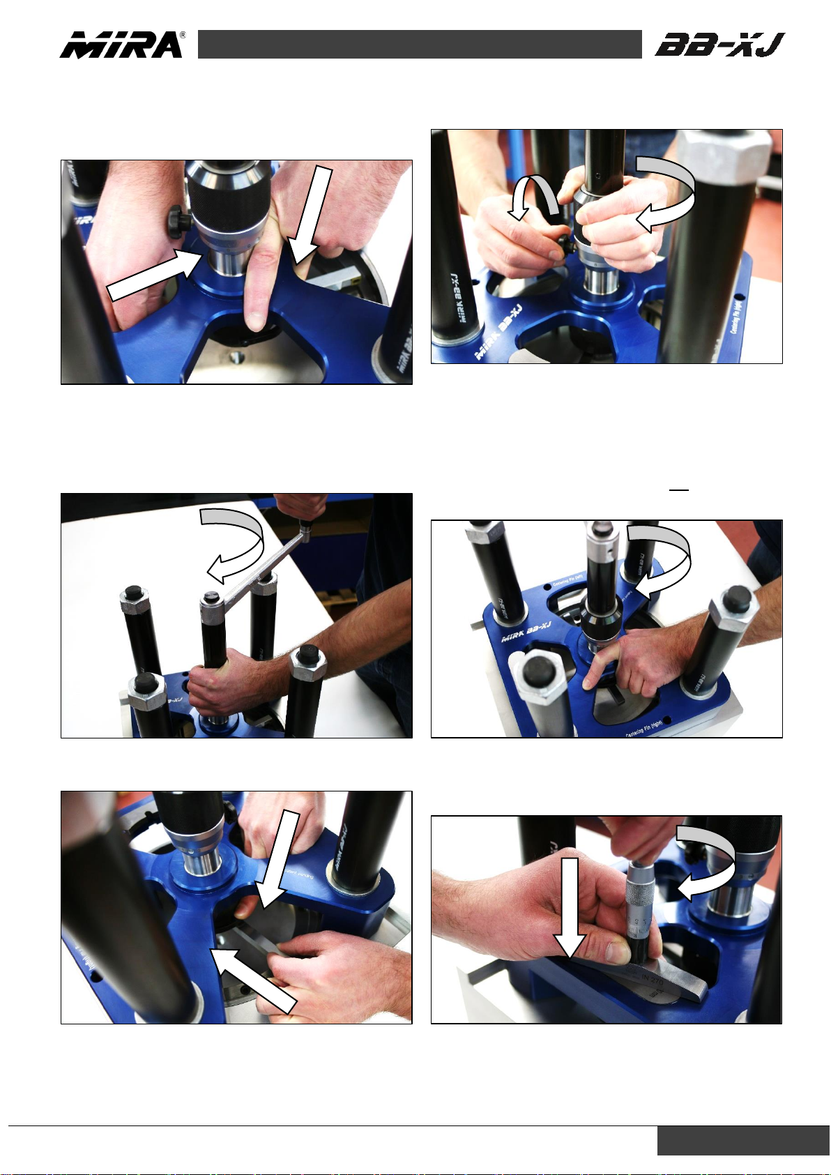
7. Press the clamp down and position the turning tool with the
cutting edge over the middle of the counterbore diameter. If
the turning tool is set too low, release the locking screw and
twist the feed nut upwards anticlockwise.
8. If not yet done, release the blocking screw. Turn the crank
handle clockwise and slowly move the feed nut off and on in
the same direction. Stop when the turning tool is slightly
touching the counterbore seat (spotting). Gently tighten the
locking screw.
9. Press the clamp down and position the turning tool just
before the counterbore seat. Release the clamp.
10. Release the locking screw. Set the desired seat depth
using the feed nut. Gently tighten the locking screw once
again. Do not feed more than 0,1mm in a single step!
11. Hold the gear sleeve on the knurled surface with your
thumb and index finger. Turn the crank handle evenly
clockwise. Once the turning tool has reached the wall of the
counterbore, slow down the rotation slightly and allow the
gear sleeve to gently make contact with your fingers. As
soon as the cutting edge is reaching the sidewall of the
counterbore, the cutting pressure and therefore the
rotational resistance will increase. Do not turn the crank
handle anticlockwise in this step!
12. Check the deployment of the BB-XJ using a depth
gauge bolt. Reference height (gauge slide) to contact
surface => 60,000mm. The measurement is made to check
the depth of the counterbore after refacing the seat.
13. If final depth has not been achieved yet, repeat steps
9-12. If the final depth has been achieved, press the clamp
down and carefully slide back the turning tool up to the front
of the counterbore seat.
For further refacing of outstanding counterbore seats:
Repeat steps 3-13

20.07.2023/v1.2BB-XJ |Serial-No.: 0220 ©(subject to change without notice)
8
Maintenance and spare parts
6.1 Lubrication of the main spindle and the advancing mechanism
Annual service:
1. Remove the vernier (F) from the advancing
mechanism (loosen worm screw (E)), but leave it on
the spindle guide (G).
2. Loosen special nut (A) and remove adapter or crank
handle (J). After removing the key (K), the mainspindle
(H) can be pulled down completely.
3. Slowly screw the advancing mechanism upward (C).
Be careful that none of the parts from the spring-
loaded threaded ring (D) get lost.
4. Clean all parts and lubricate them.
5. When screwing on the advancing mechanism (C), be
sure the threaded ring (D) is being fixed again in the
same position. When reaching the guide (G) with the
threaded ring (D), press down the advancing
mechanism (C) in order to reduce the play of the
springs (L) to zero.
6. When placing the main spindle (H), be sure the
compensating spring (B) is properly fixed.

20.07.2023/v1.2BB-XJ |Serial-No.: 0220 ©(subject to change without notice)
9
6.2 Spare parts drawing BB-XJ

20.07.2023/v1.2BB-XJ |Serial-No.: 0220 ©(subject to change without notice)
10
6.3 Spare part list to spare parts drawing BB-XJ
When ordering spare parts, the indication of the serial- and the manufacturing number is always essentially.
Spare parts valid with serial-No.: 0220 from manufacturing-No: 0106 < …
Description Pos. Quantity Part-No.:
Adapter 1 1 18042.4.2474
Main spindle assembly 2 1 18042.3.2390
Threaded ring 3 1 18042.4.2322
Main body 4 1 101150.1.5877
Support bushings 5 4 101150.1.6644
Guide sleeves 6 2 101150.1.7195
Advancing device metric 7 1 18042.4.2323
Vernier 8 1 18042.4.2324
Cover disk 9 1 18042.4.2325
Special-nut 10 1 18042.4.2473
Guide 11 1 18051.3.2321
Gauge slide 12 1 18051.4.1292
Locating/centering pins Ø12x28 13 2 101150.3.5875
Locking sleeves 14 4 101150.1.5878
MB90 BB-XJ - 5° turning tool 15 1 101150.2.5883
Extension adapter 16 1 101150.1.5880
Crank handle body 17 1 10151.3.2456
Handle grip M10 18 1 10141.4.1242
Grooved axial ball bearing 19 2 1LAR20
Compensating spring 20 1 1MAS24.5
Setscrew 21 1 1N0024M05x004
Setscrew 22 2 1N0024M06x006
Key 23 1 1N087005x05x16
Set screw slotted, Polyamide 24 2 1N1073M05x006
Locking screw 25 1 1NH6336M5KU
Compression spring 26 6 1MDF03
Washer 27 4 1N0721M30
Screw nuts M30x2 28 4 1N0137M30x02
Dowel pin h6 29 1 1N085804x010
Torx screw 30 1 1MTS04.0
Allen key 2.5 31 1 1WIS2.5
Allen key 3.0 32 1 1WIS3.0
Cutting insert (cast) AP5210 33 1 1KWP00105
Torx wrench T15 34 1 1KSZ00423
Peli Air Case with foam inlay 100 1 101150.2.7102

20.07.2023/v1.2BB-XJ |Serial-No.: 0220 ©(subject to change without notice)
11
6.4 Spare parts drawing BB-spindle
Please pay attention!
To ensure precise functioning of the main
spindle and to avoid damage, corresponding
replacement work should only be carried out
by an authorised MIRA specialist dealer or by
the manufacturer.

20.07.2023/v1.2BB-XJ |Serial-No.: 0220 ©(subject to change without notice)
12
6.5 Spare part list to spare parts drawing BB-spindle
When ordering spare parts, the indication of the serial- and the manufacturing number is always essentially.
Spare parts valid with serial-No.: 0220 from manufacturing-No: 0106 < …
Description Pos. Quantity Part-No.:
Main spindle 1 1 18051.3.2351
Gear bushing 2 1 18041.4.2352
Toothed wheel assembly 3 2 18041.4.1361
Advancing device assembly 4 1 18041.4.2357
Lifting bow (clamp) 5 1 18041.4.2354
Driving gear wheel 6 1 18041.4.1087
Gliding ring 7 1 18041.4.2353
Lifting bow screw 8 2 18041.4.2358
Cover plate 9 1 18041.4.1148
Compression spring 10 6 1MDF18
Pressure bolt 11 1 1MDB08/20
Retaining ring 12 1 1N0818A24
Dowel pin h6 13 3 1N085803x006
Allen screw 14 3 1N0272M05x008

20.07.2023/v1.2BB-XJ |Serial-No.: 0220 ©(subject to change without notice)
13
Notes

20.07.2023/v1.2BB-XJ |Serial-No.: 0220 ©(subject to change without notice)
14
Notes
Table of contents
Other Mira Industrial Equipment manuals
Popular Industrial Equipment manuals by other brands

Clenergy
Clenergy PV-ezRack Code-Compliant Planning and Installation Guide

ABB
ABB HT845196 Operation manual

Tescom
Tescom TC-5063C operating manual

Jäger
Jäger Z80-H445.06 S5AW2/2 manual

Zimmer
Zimmer MATCH LWR50L-25 Series Installation and operating instructions

Wenger
Wenger GEARBOSS Mobile Kiosk Electric Kit owner's manual