First through innovation
0086
Mira, Inc.*414 Quaker Highway * Uxbridge, MA 01569 * Tel: 508-278-7877 * 800 847-6472 * Fax: 508-278-4555 p.
9
Be sure that the gas cylinder is properly secured to a rack or the MIRA Equipment Carrier. It is
important to prevent the cylinder from tipping over. If the cylinder was not stored critically, set
aside for 24 hours. If it is hot or cold due to storage conditions, set it aside for 24hrs to equilibrate
to room temperature.
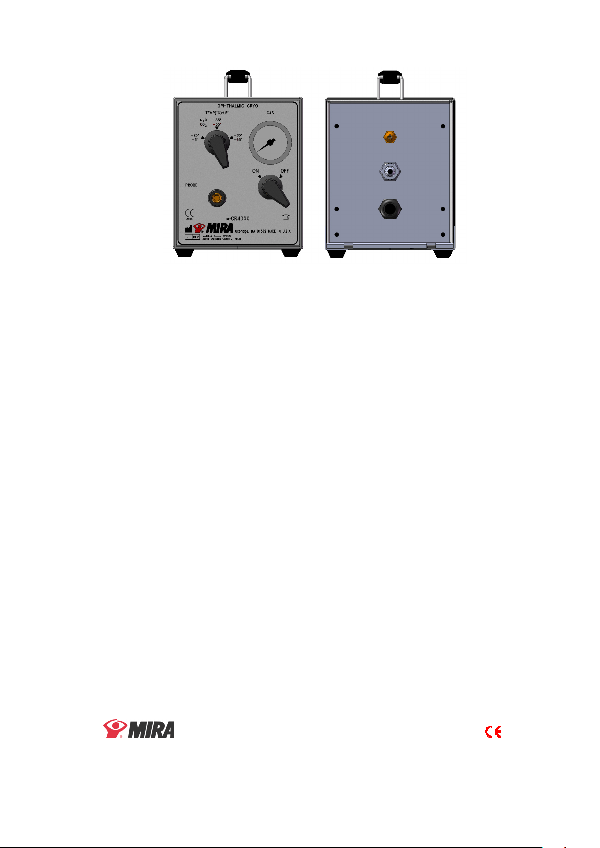
Make sure that the “ON/OFF” valve on the front panel of the console is in the “OFF” position.
Connect one end of the high-pressure hose to the “gas input” on the back of the console and the
other end to the gas supply through the Micro-Filter Assembly. Tighten both the 5/8 hex nuts by
hand then tighten them using an appropriate wrench. Attach cylinder connector to the gas supply
cylinder per the appropriate procedure below.
For CGA connector;
a. Place the adaptor against the mating outlet of the cylinder valve.
b. Engage the quick-coupling nut and tighten by hand.
For T-Yoke connector;
a. To ensure a tight seal, use the washer supplied with the cylinder.
b. Place the T-Yoke connector over the cylinder stub valve.
c. Tighten the “T” handle by hand.
Connect one end of the 25ft. Scavenger hose to the rear panel fitting labeled “System Exhaust”
Connect the other end to an aspiration system or equivalent.
Note; Use of the scavenger hose will result in quieter operation of the CR4000.
Check to be sure that the “ON/OFF’ valve on the front panel of the Cryo console is in the “OFF”
position. Then, completely open the valve on top of the gas cylinder by turning it counter-
clockwise. When the cylinder valve is completely open, turn it back (clockwise) one quarter-
turn.
This prevents the cylinder valve freezing and locking in the open position.
Listen and look for leaks at either end of the high-pressure hose. An audible hiss or frost on a
fitting identifies a leak. A leak can be corrected by tightening the appropriate 5/8 nut(s) on the
high-pressure hose. Any leak in the system will adversely affect the system performance,
particularly freezing and defrosting.
5.0 FOOT-SWITCH OPERATION
The foot-switch has approximately 12ft. (3.66metres) of reach in any direction.
A hissing sound is present each time the foot-switch is depressed or released.
Depressing the foot-switch pedal at any compass point will instantly freeze the probe tip.
Releasing the foot-switch pedal will instantly defrost the probe tip.
A popping sound may be heard from the relief valve if the foot-switch is depressed within 30
seconds of its last release. This is normal. The purpose is to lower the exhaust pressure so that
freezing can take place.