Mirage B-2516-G User manual

MIRAGE B-2516-G
1
TABLE OF CONTENTS
GENERAL INFORMATION..........................................................................................................2
SPECIFICATIONS.......................................................................................................................2
INSTALLATION ...........................................................................................................................3
Front Panel Switches/LED's............................................................................................3
Rear Panel Connectors...................................................................................................3
Internal Adjustments .......................................................................................................4
TUNING PROCEDURE...............................................................................................................4
Visual Inspection & Initial Settings..................................................................................4
Setting the Idling Current................................................................................................5
Measurement of Insertion Loss.......................................................................................5
Tuning the Amplifier........................................................................................................6
Setting the Trip Points.....................................................................................................7
Adjusting The Receive Preamp.......................................................................................8
TROUBLESHOOTING.................................................................................................................9
Technical Assistance ......................................................................................................9
SCHEMATIC DIAGRAM..............................................................................................................10

MIRAGE B-2516-G
2
GENERAL INFORMATION
The Mirage B-2516-G is the next generation of Power Amplifiers for 144-148 MHz. New
features make it the most useful and versatile amplifier available. Features include automatic
power shut-down circuitry for protection against high antenna VSWR, high temperature and
excessive R.F. power input. A newly designed GaAsFET receive pre-amp provides high gain and
low-noise amplification for weak signal applications. The pre-amp includes an attenuator to
reduce signal output level. This is useful in preventing Receiver Overload and subsequent
Intermodulation Distortion caused by strong signals. Provision is made for automatic or remote
(external) keying, and for remote control of all front panel functions using the Mirage RC-1 Remote
Control Unit. The Mirage B-2516-G is capable of FM, SSB, and CW operational modes.
SPECIFICATIONS
Frequency Range: 144 to 148 MHz
R. F. input power (Drive): 1 to 40 Watts
R. F. output power: 160 Watts with 25 Watts drive.
Duty Cycle: Intermittent (ICAS)
Modes: FM, SSB, CW
Receive Pre-amp: GaAsFet, Gain 21/15 dB-Nominal. Noise
figure less than 0.6 dB. 1 dB compression
point greater than -13 dBm input (Nominal)
VSWR Power Shut-down point: 3:1 Approximately
R.F. input Power Shut-down point: 40 Watts Nominal
Temperature Power Shut-down point: 175 Degrees F
Keying: Automatic (R.F. sensing) or
remote (external).
Input/Output Impedance: 50 ohms
R.F. connectors: SO-239 (UHF)
Remote keying connector: RCA phono
Remote control connector: 6 pin Molex
Supply voltage: 13.8 VDC (for full R.F. power output)
Supply current: 25 amps (nominal)
Fuse: Low voltage, fast blow, 35 amps
Physical Dimensions: 12 x 3 x 5 1/2 inches
Weight: 5 pounds
MIRAGE B-2516-G
3
INSTALLATION
The Mirage B-2516-G may be mounted using the brackets (supplied when request is returned
via warranty card) or simply placed in a convenient operating position. In either case, there must
be adequate ventilation for the finned heat-sink. This generally means at least 1 inch clearance
from the sink to any surrounding enclosure and an unobstructed flow from the front to the back of
the sink. CAUTION: With extended use, the heat sink becomes very hot. If it is necessary to
extend the D.C. power leads, use a minimum #8 gauge wire. Use a minimum length of qood
quality 50 ohm cable between the radio and the amplifier. The antenna system should have a
VSWR of 1.5:1 or better for best performance. The receiving pre-amp gain is set to the high value
at the factory. To switch to minimum gain, move the DIP switch located under the left side cover
near the power supply leads to the "up" position. The switch may be accessed through the twelfth
slot from the rear using an appropriate small tool. If desired, the transmit relay hold-in (hang-time)
may be changed by adjusting the potentiometer located behind the seventh slot from the rear on
the right side of the amplifier. If external amplifier keying is desired, a switched ground connection
must be provided to the center pin of the RCA phono jack.
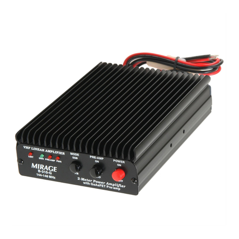
Front Panel Switches/LED's
POWER ON/OFF SWITCH: Turns the D.C. power on or off.
SSB/FM SWITCH: Selects relay time delay
for the mode of operation.
The relay drop time is lengthened for the SSB mode
of operation.
PRE-AMP ON/OFF SWITCH: Turns Pre-Amp power on or off.
POWER LED: Indicates that D. C. power is applied.
PRE-AMP LED: Indicates that the pre-amp is turned on.
TX LED: Indicates that the amplifier is keyed on.
SWR/OVERLOAD LED: Indicates amplifier shut-down due to excessive
VSWR, temperature, or R. F. drive power.
Rear Panel Connectors
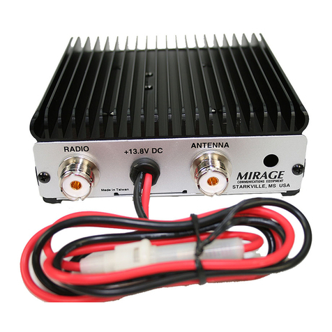
RADIO (SO-239): R. F. input from radio.
ANT (SO-239): R. F. output to antenna.
RCA phono (Unmarked): Remote keying.
Molex (Unmarked): Remote control.

MIRAGE B-2516-G
4
Internal Adjustments
SSB DELAY: This allows the R.F. relay "hang-time" or delay
to be adjusted to the time desired.
PRE-AMP ATTENUATOR SWITCH: Sets the pre-amp gain to full or reduced value.
INPUT VSWR AND OUTPUT POWER: These adjustments are made at the factory and
should not require field adjustment.
PRE-AMP TUNING: These adjustments are also made at the factory
for best gain
and noise figure performance.
They should not require field adjustment.
TUNING PROCEDURE
Frequency: 144 to 148 Mhz, Input: 25 watts, Output: 160 Watts
Visual Inspection & Initial Settings
1.
The first step is to give the amplifier a good visual inspection. Turn the amplifier over and
gently tap it against the edge of the desk to remove any foreign object that may be loose
in the unit. Next take a stiff brush and go over the entire board to verify that there are no
foreign objects.
2.
Check the appearance of the unit. Ensure that all LED's on the front are flush with face,
no scratches, etc.
3.
Check for tightness of panel connectors.
4.
Check the 3 & 6 turn coils and ensure that the turns are spread at least the width of an
exacto knife
5.
Spot check the transistors for tightness.
6
Adjust all pots located on the amplifier for minimum resistance in reference to ground.
Adjust all capacitors 1/2 turn away from fully meshed position.
7.
Turn front panel Power ON/OFF switch to OFF.
8.
Turn front panel Preamp ON/OFF switch to OFF.
9.
Strip the power leads.

MIRAGE B-2516-G
5
Setting the Idling Current
1.
Connect the amplifier to the dummy load before making any other connections to prevent
damage.
2.
Lift one end of the input voltage protection fuse from its socket.
3.
Ensure that your DC voltage from the power supply is off.
4.
Connect the power supply and all other connections to the amplifier. Ensure that the
exciter radio is off until directed.
5.
Place a SHORTED RCA plug into the RCA jack located on the rear of the amplifier. This
will cause the transmit relay to energize when the amplifier power is switched on.
6.
Using the lifted end of the protection fuse and the unused side of the fuse socket, insert a
meter capable of reading current from 0 milliamps to 5 amps.
7.
Apply power to the amplifier and turn the unit on while observing the current reading on
the meter.
NOTE: IF CURRENT SURGES TOO HIGH, IMMEDIATELY REMOVE POWER!
8.
Upon application of power, the initial reading should be approximately .44 amps of
current.
9.
Locate and adjust the power amplifier bias pot, R42, to reflect an additional 20 milliamps
on the meter, for a reading of approximately .64 milliamps.
10.
Turn the unit off and remove the DC power.
11.
Remove the shorted RCA plug from the RCA jack on the amplifier.
12.
Disconnect the meter from the circuit and place the fuse back in the holder.
Measurement of Insertion Loss
1.
Ensure that the power is in the OFF position on the front panel.
2.
Set the frequency of the exciter radio to the center of the allocated band (in the case of
the Amateur band, 146.000 MHz).
3.
Turn the exciter radio on and adjust the output power to 5 watts FM or CW when keyed.
4.
Verify that there is no reflected power.
5.
Increase the power to 10 watts and measure the insertion loss through the relay contacts.
6.
With 10 watts injected, the output watt meter should read 8.2 watts or more. The
difference is the insertion loss, which should be no more than 1.8 watts. The input
reflected should read less than 400 milliwatts.

MIRAGE B-2516-G
6
Tuning the Amplifier
NOTE:
Key-up by applying RF during test only. While tuning & testing, always observe
current draw, spectrum analyzer and input VSWR.
1.
Key the exciter radio and adjust the output power to 10 watts FM or CW.
2.
Turn the DC power supply on.
3.
Place the front panel power switch in the ON position.
4.
Quickly, and with minimum key up time, adjust the C65 trimmer capacitor on the output
side of the final power transistors for the maximum power output as shown on the output
power meter and minimum current draw.
5.
Simultaneously observe the input reflected power meter and adjust C65 for the minimum
VSWR on the input while maintaining the maximum power that can be obtained on the
output.
6.
Observe the spectrum analyzer and readjust C65 if any spurs or oscillations are present.
7.
Adjust capacitor C44, located on the input side of the power amplifier, for minimum
reflected power on the input meter and maximum output power.
8.
Again, observe the spectrum analyzer and readjust if any spurs or oscillations are
present. Unkey the transmitter.
9.
Place the power switch on the front panel in the OFF position.
10.
Increase the drive signal on the exciter radio to 25 watts.
11.
Place the power switch on the front panel in the ON position.
12.
Repeat steps 4 through 8 above.
13.
Check the power out and input reflected for tolerances at 144, 146, and 148 MHz. The
power should read at least 160 Watts. Current at full power output should not exceed 24
amps at 13.8 vdc.

MIRAGE B-2516-G
7
Setting the Trip Points
1.
The next step is to set the Overdrive trip point at 40 to 45 watts. This is accomplished by
the selection of the proper trip diode ZD2, which is normally a 1N5252. If circuit trips too
soon, a 2pf capacitor (C3) may be placed at junction of R1-C1 from strip line to ground of
circuit board. Or, you may substitute a short piece of 50 ohm mini coax for C3. It may be
soldered to strip line. Solder the center conductor to strip line at the R1 -
C1 junction.
The shield should be soldered to ground. Trim coax to proper length to set trip point at 40
to 45 watts drive. Check trip at both ends of band 144 MHz, 148 MHz. Set trip at 40
watts at most sensitive end of band.
2.
Set the drive level to a level that will give 160 watts indicated on the output watt meter.
Unkey the transmitter. Remove the coax marked antenna on the amplifier (output coax).
Momentarily key up or apply drive signal to amplifier. Amplifier should go immediately
into VSWR fault. DO NOT HOLD THIS KEY CLOSED FOR MORE THAN 3 TO 4
SECONDS, as the output of amplifier is open with no load on it. If amplifier does not go
into fault, the SCR circuit is defective. If amplifier does go into fault, proceed to next step.
Be sure to check at the upper and lower limit of the band.
3.
Next, place a 3:1 mismatch dummy load at the output of the amplifier. The shut-down
trip point must be set to the most sensitive end of the band. The trip may be adjusted so
the circuit just trips at 158 to 162 watts. Adjust the trip by selecting proper diode as
shown on print as ZD3, and/or select the proper capacitance C25 across R24, the 62
ohm resistor shown on the pick-up trace. A piece of 50 ohm coax, approximately 2
inches long, may be substituted for C25 and cut to proper length to adjust the trip point.
Remove the 3:1 dummy load and reconnect the output coax. Note: C25 may be
removed or temporarily disconnected to make the shutdown circuit more sensitive.
4.
Set SSB - FM switch to SSB. Key up and set SSB relay pot for 2 to 3 seconds of hang
time on the relay after it is unkeyed.

MIRAGE B-2516-G
8
Adjusting The Receive Preamp
1.
Remove the input and output coax cables for the amplifier radio and antenna connectors.
MAKE SURE YOU TURN THE TRANSMIT RADIO OFF.
2.
Connect a coax from signal generator through a 5 dB pad to output connector on antenna
connector of amplifier. Set generator to mid-band 146 MHz with a -55dBm signal.
3.
Connect a coax from spectrum analyzer to the radio input of amplifier.
4.
Set spectrum analyzer to read 10dB per cm vertical deflection. Apply a 3cm reference signal
from generator (approximately -55dBm).
5.
Turn on receive amplifier. Signal should increase 1.5 cm (15dB) with dip switch SW4 in low
gain position and 2.1 cm (21dB) in the high gain position. (*Note: Because of the devices
used, 12 dB gain is possibly all the gain that may be achieved in a worst case event in the high
gain position.)
6.
If you do not have sufficient gain, adjust the variable capacitor C22 for 15 dB gain with S4 dip
switch in low gain position.

MIRAGE B-2516-G
9
TROUBLESHOOTING
The Mirage B-2516-G is designed for long, trouble-free performance and should not require
extensive troubleshooting in the field. Many causes of common malfunctions are eliminated by the
built-in protective circuitry.
NOTE: In the event of automatic power shut-down, the amplifier must be turned off and the cause
of shut-down determined and removed. In case of difficulty, check the following before assuming
amplifier malfunction:
a. Loose antenna or power supply connections.
b. VSWR of antenna system.
c. Coaxial cables from radio to amplifier, and amplifier to antenna.
d. Output voltage of power supply.
e. Power output of radio.
f. Improper fuse rating.
Technical Assistance
If you have any problem with this unit,first check the appropriate section of this manual. If the
manual does not reference your problem or your problem is not solved by reading the manual, you
may call MIRAGE at 601-323-8287. You will be best helped if you have your unit, manual and all
information on your station handy so you can answer any questions the technicians may ask.
You can also send questions by FAX to 601-323-6551. Send a complete description of your
problem, an explanation of exactly how you are using your unit, and a complete description of your
station.
Other manuals for B-2516-G
1
Table of contents
Other Mirage Amplifier manuals

Mirage
Mirage B-215-G User manual

Mirage
Mirage B23A User manual

Mirage
Mirage A-1015-G User manual

Mirage
Mirage C-2512-G User manual

Mirage
Mirage B 5018 G User manual

Mirage
Mirage B-2516-G User manual

Mirage
Mirage B 1018 G User manual

Mirage
Mirage B-320-G User manual

Mirage
Mirage KP-2 Series User manual

Mirage
Mirage C-22-G User manual

Mirage
Mirage BD-38-G User manual

Mirage
Mirage B-34 User manual

Mirage
Mirage A1015R User manual

Mirage
Mirage KP-1 Series User manual

Mirage
Mirage A1015 User manual

Mirage
Mirage B-24-G User manual

Mirage
Mirage B-34-G User manual

Mirage
Mirage B23A User manual

Mirage
Mirage B 1018 G User manual

Mirage
Mirage B 1018 R User manual