manuals.online logo
Brands
  1. Home
  2. •
  3. Brands
  4. •
  5. Mircom
  6. •
  7. Controllers
  8. •
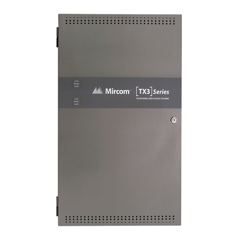
  9. Mircom TX3 Series Manual

Mircom TX3 Series Manual

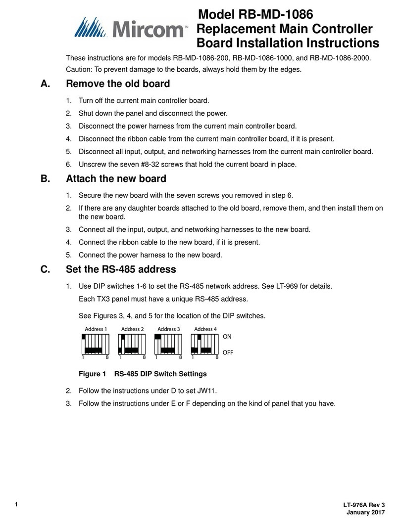
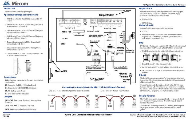
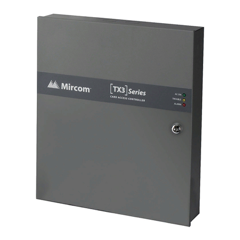
TX3 Card Access Installation Quick Reference
Version 0 Card Access System Installation Quick Reference for more information read the LT-6906 Card Access System Manual
LT-6910 available on USB flash drive or website WWW.MIRCOM.COM
SW1
SW1 sets the Telephone Access controller network address. Use
DIP switches 1 to 5 to set the network address. DIP switches 6, 7
and 8 should remain at the factory set values.
Terminal connectionsTe rmin al connections
for two card readersfor two car d rea de rs
RS-485 terminals forRS-485 terminals for
multiple controllersmultiple controllers
Power terminalsPower terminals
OUTPUT 7 OUTPUT 8
12V 12V
Door StrikeDoor Strike
OUTPUT 1
NC C NO NC C NO NC C NO NC C NO NC C NO NC C NO
CommonCommon
Maglock 1Maglock 1
Door Strike 1
CommonCommon
NormallyNormally
ClosedClosed
NormallyNormally
OpenOpen
External
power
supply
External
power
supply
OUTPUT 2 OUTPUT 3 OUTPUT 4 OUTPUT 5 OUTPUT 6
ON/OFF SwitchON/OFF Switch
SW1SW1
P6 -P6 - P5 +P5 +
-S+ -S+
INPUT OUTPUT
INPUT 1 INPUT 8
Reader AReader A
Door SenseDoor Sense
Reader BReader B
Request to ExitRequest to Exit
GeneralGeneral
PurposePurpose
BEEPER
RED
LED LED PWR+
GRN
COM(-)
COM(-)
DATA 0
DATA 1 COM(-)
COM(-)DATA 0
DATA 1
BEEPER
RED
LED LED PWR+
GRN
SW2SW2
USB connectionUSB connection
Inputs 1 to 8Inputs 1 to 8 Outputs 1 to 6Outpu ts 1 to 6
Connection to 12VConnection to 12V
battery backupbattery backup
Outputs 7 and 8Outputs 7 and 8
Connection forConnection for
front door LEDsfront door LEDs
OFF ON
+
-
Black Red
12 V12 V BATTERY
BAT- BAT+
JW4JW4
JW2JW2
JW6JW 6
JW3JW3
JW5JW 5
JW1JW 1
LEDsLEDs
ACAC
TROUBLETROUBLE
ALARMALARM
WIEGAND #1 WIEGAND #2
RS-485RS-485
Tamper SwitchTamper Switch
GroundGround
TerminalTerminal
optional
TX3-USB-AD InterfaceTX3-USB-AD Interface
P7P7
16 AWG16 AWG
P3P3
TX-IP Module InterfaceTX-IP Module Interface
P4P4
Inputs 1 to 8
Inputs 1 to 8 are programmable inputs. You may
configureeachinputforoneofthefollowingactions
or use the default values.
•Request to Exit (reader A)
•Request to Exit (reader B)
•Door sense (reader A)
•Door sense (reader B)
•General purpose input
Card Reader Connections
Thediagram shows
a connection color
scheme for a
Mircom reader.
BEEPER
RED
LED LED PWR+
GRN
COM(-)
COM(-)
DATA 0
DATA 1
Yel GrnRed
Brn Wht Blk
WIEGAND #1
Jumpers
JW1. Leaveopen.Shortonly when updatingfirmware.
JW2. Leaveopen.Shortonly when updatingfirmware.
JW3. Leave open. Not used.
JW4. Leave open. Not used.
JW5. Leave open. Not used.
JW6. JW6 is not used and by default is open.
Outputs 1 to 6
Outputs 1 to 6 are relay contact programmable normally open
(NO) or normally closed (NC) outputs. The supply for the Door
Strike or Maglock is not to exceed:
• 125 VAC / 2 A
• 30 VDC / 1 A
Outputs 7 and 8
Outputs 7 and 8 are programmable and provide:
•12 Vdc
•a maximum output of 700 mA each, for a combined total
output of 1 A. For example, if output 7 provides 700 mA,
then output 8 provides 300 mA.
Ground Terminal
The Card Access system is equipped with a 16 gauge electrical
wire attached to the panel chassis Ground Terminal. Do not
disconnect this wire.
Attach the end of the supplied wire to a suitable grounding wire
16 gauge or thicker. Attach the other end to the cold water
ground.
Connections
USB. Computerconnectionforfirmwaredownloadand
configuration.
P3. Connector for TX3-USB-AD RS-485 to USB
Adapter.
P4. Connector for TX3-IP Module.
P5, P6. Battery connections.
P7. AC, Trouble and Alarm LEDs.
SW2
SW2setstheCardAccesscontroller RS-485 network address and
determines how the IP module get its IP address (if installed).
•Use DIP switches 1 to 6 to set the RS-485 network address.
Address 1
ON
OFF
Address 4
Address 2 Address 3
18181818
RS-485
TheRS-485connection consists of an input and output terminal.
ConnecttheRS-485outputterminaltotheRS-485inputterminal
of the next controller.
Connect the last controller on the network to the RS-485 input
terminal. Refer to LT-6906 for end of line resistors to be used on
the first and last nodes of network. The RS-485 terminal consists
of + (positive), - (negative), and S (Shield) connections.
•Keep DIP switch 7 at the factory set value
•Set DIP switch 8 OFF to get IP addressfrom DHCP server.
•SetDIPswitch8ONtogetIPaddressfromTX3Configurator
software.
TX3 Card Access Installation Quick Reference
Version 0 for more information go to the USB flash drive or website and read the LT-6906 Card Access System Manual
LT-6910 WWW.MIRCOM.COM
Card Access System Quick Reference
Single Panel Wiring
Basic Wiring
1. Turn the controller power switch to OFF.
2. Connect the card readers to Weigand terminal blocks.
3. Connect the door strike or maglock to Output 1.
4. Connect the controller supply.
5. Set SW2 with a unique RS-485 network address.
6. Turn the controller power switch to ON (a correctly wired controller will show a green AC LED).
Installation Prerequisites
Ensure there is a provision for a ground circuit. The Card Access System assembly must be grounded by a qualified
electrician. An improperly grounded unit can result in equipment malfunction and void the warranty.
Use the latest Card Access System controller firmware. Mircomperiodicallyupdates panelfirmware and Configurator
Software to add features and correct any minor inconsistencies. For information about the latest firmware or software
visit the ‘Manuals and Downloads’ section of the Mircom website at www.mircom.com.
Before Starting the Configuration
Configure the system using the Configurator software using a USB or modem connection. Verify the following:
Ensure that the controller and all connected devices and components are fully operational.
Ensure the controller DIP Switches are set with a unique RS-485 network address.
Ensure the Configurator software is set with the correct controller RS-485 network address.
Ensure that your PC is set with the correct date and time.
•
•
•
•
•
•
To Start the Configuration
1. Connect the PC to the controller using the USB port or modem connection.
2. LaunchtheConfiguratorandselectthecorrectcontrolleryouare connecting to(onthe basis ofname,panellabel, panel
model, and network address).
3. Click Connect. The connection icon appears in the Configurator tool bar.
4. Ensure that the panel is configured with the correct date and time.
5. Configure the Card Access system using the instructions in the LT-995 Configuration and Administration Manual.
Relay contact
RS-485
3 wires
18 AWG
Shielded Cat 5 cable
grounded at one end
Programmable outputs
Combined 1 amp output
12 Vdc
700 mA max. each
1 pair
18 AWG
Door Sense
(Reader A )
R
equest to Exit
(
Reader A )
1 pair
22 AWG
1 pair
22 AWG
1 pair
22 AWG
General
purpose input
1 pair
22 AWG
1 pair
22 AWG
6ot1STUPTUO8ot1STUPNI
Card Access
System
Electrical room
Card Reader A
Maximum distance from the card reader
Use 20 AWG wire for 500 feet
Use 22 AWG or 24 AWG for 250 feet
Card Reader B
Configurable for the following actions
Request to Exit
(Reader B )
Door Sense
(Reader B )
OUTPUTS 7 to 8
Card readers supplied by Mircom
require shielded wiring. If other
card readers are used refer to their
reader wiring requirements.
Shield
120 VAC
60HZ
Power
transformer
See LT-6906
for details
Power
transformer
for AC or DC Door
strike supply
The following figure shows the various controller connections
IMPORTANT
Thisdocumentisforreferenceonlyanddoesnotreplacetheexistingdocumentation. Formoredetailed
information refer to the documentation on the USB flash drive or Mircom website (www.mircom.com).
Wiring requirements
Install all transformers outside the Lobby Control Unit enclosure.
Unlessspecifiedotherwise,allwiringisamaximumlengthof1000ft. TheRS-485wiringmaximumlengthis4000ft.
The door strike power supply depends on the door strike power requirements.
•
•
•
Other manuals for TX3 Series

29

Other Mircom Controllers manuals

Mircom TX3 Series User manual

Mircom

Mircom TX3 Series User manual

Mircom OpenBAS-LC-NX12R User manual

Mircom

Mircom OpenBAS-LC-NX12R User manual

Mircom OpenBAS-HV-NX4AO User manual

Mircom

Mircom OpenBAS-HV-NX4AO User manual

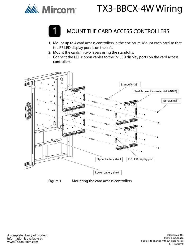
Mircom TX3-BBCX-4W User manual

Mircom

Mircom TX3-BBCX-4W User manual

Mircom OpenBAS-HV-NX10 Series User manual

Mircom

Mircom OpenBAS-HV-NX10 Series User manual

Mircom RAM-2944LCD User manual

Mircom

Mircom RAM-2944LCD User manual

Mircom TX3-BBCX-4W Reference guide

Mircom

Mircom TX3-BBCX-4W Reference guide

Mircom OpenBAS-NWK-ETH3 User manual

Mircom

Mircom OpenBAS-NWK-ETH3 User manual

Mircom TX3 Series Manual

Mircom

Mircom TX3 Series Manual

Mircom RB-MD-1086 Series User manual

Mircom

Mircom RB-MD-1086 Series User manual

Mircom TX3 Series User manual

Mircom

Mircom TX3 Series User manual

Popular Controllers manuals by other brands

Mitsubishi Electric PZ-61DR-E Simple operation manual

Mitsubishi Electric

Mitsubishi Electric PZ-61DR-E Simple operation manual

Mitsubishi Electric MELSERVO-J4 MR-J4 A Series instruction manual

Mitsubishi Electric

Mitsubishi Electric MELSERVO-J4 MR-J4 A Series instruction manual

Kelly MiniKLS7210NV user manual

Kelly

Kelly MiniKLS7210NV user manual

Pepperl+Fuchs KFD0-SD2-Ex2.1 45 Series manual

Pepperl+Fuchs

Pepperl+Fuchs KFD0-SD2-Ex2.1 45 Series manual

rotork K-TORK Series Installation & maintenance instructions

rotork

rotork K-TORK Series Installation & maintenance instructions

Keating Of Chicago UA Flame Master Lo-Temp Griddle Service instructions

Keating Of Chicago

Keating Of Chicago UA Flame Master Lo-Temp Griddle Service instructions

Vadsbo LCC60 installation instructions

Vadsbo

Vadsbo LCC60 installation instructions

Thermo Scientific Uniry Lab Services UP150 Operation

Thermo Scientific

Thermo Scientific Uniry Lab Services UP150 Operation

Seiko PS-110 operating manual

Seiko

Seiko PS-110 operating manual

GGM GUB Series manual

GGM

GGM GUB Series manual

3Ware 9590SE Series User guide addendum

3Ware

3Ware 9590SE Series User guide addendum

Honeywell TRADELINE VR4304 manual

Honeywell

Honeywell TRADELINE VR4304 manual

Arturia Keystep manual

Arturia

Arturia Keystep manual

janitza Prophi 6R manual

janitza

janitza Prophi 6R manual

Penn TC3B23 installation guide

Penn

Penn TC3B23 installation guide

Sensus 243-12-4 manual

Sensus

Sensus 243-12-4 manual

Mitsubishi Electric NZ2GN2S-D41P01 user manual

Mitsubishi Electric

Mitsubishi Electric NZ2GN2S-D41P01 user manual

YASKAWA SI-ES3 installation manual

YASKAWA

YASKAWA SI-ES3 installation manual

manuals.online logo
manuals.online logoBrands
  • About & Mission
  • Contact us
  • Privacy Policy
  • Terms and Conditions

Copyright 2025 Manuals.Online. All Rights Reserved.