MIRKA AIROS 350CV User manual


2Mirka® AIROS • 77 mm (3"), 125 mm (5") & 150 mm (6") • Tool manual
Warranty
Mirka warrants that your components are free from manufacturing and material defects.
Mirka components have a 1-year warranty starting from the date of purchase. Only manufacturing and material
defects are covered by the warranty.
If a problem occurs caused by a manufacturing defect material or by workmanship, Mirka will repair your
component free of charge in accordance with the warranty terms and conditions stated herein. To keep your
component warranty valid the component must be used, maintained and operated in compliance with the
operating instructions.
Terms and conditions
Mirka’s component warranty covers defects in material and workmanship.
Components covered by the warranty:
• motor drive
• sanding unit
• polishing unit
• power supply
• communication gateway
Warranty does not cover:
• any damage caused or resulting from transport, receipt of delivery, installation, commissioning, misuse, neglect
in usage or maintenance, accidents, exposure to extreme unacceptable ambient temperature, acids, water,
unsuitable storage, excessive impact, or operation outside the rated specifications.
• defects caused by spare parts, accessories or components other than Mirka original spare parts or accessories.
• normal wear and tear items such as: backing pad, break seal, exhaust fitting, bearings, rubber mount, signal cable
or power cable.
• components that have been: modified, repaired or repair attempts (by other than Mirka authorized service), partly
or completely disassembled components.
No other than Mirka have the authority to change, extend or add to given warranty terms and conditions.
The manufacturer cannot be hold responsible for consequential damages compensations for downtime, production loss,
injuries or property damages.
A warranty claim must be submitted with as short delay as possible. A warranty claim must be submitted within the
warranty period.

2Mirka® AIROS • 77 mm (3"), 125 mm (5") & 150 mm (6") • Tool manual Mirka® AIROS • 77 mm (3"), 125 mm (5") & 150 mm (6") • Tool manual 3
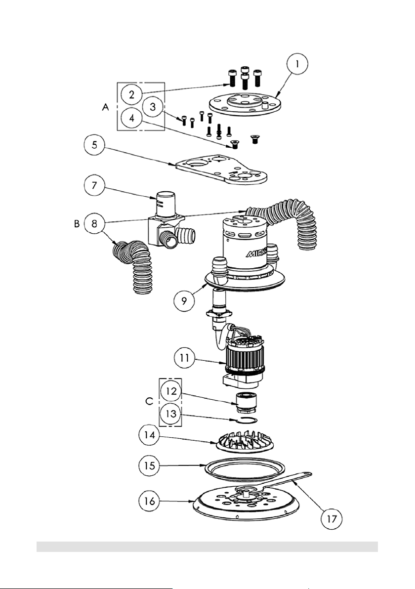
Installation overview
Installation steps
1. Remove dust protector cap from the connector.
2. Mount the tool on a matching counter-flange. If the force sensor
or the robot used has a flange of a different size an adapter may be
required. If the counter-flange is larger by a significant amount there
may be a need for an increase in tool offset on the adapter to prevent
unnecessary wear, or obstruction of the hose and cable.
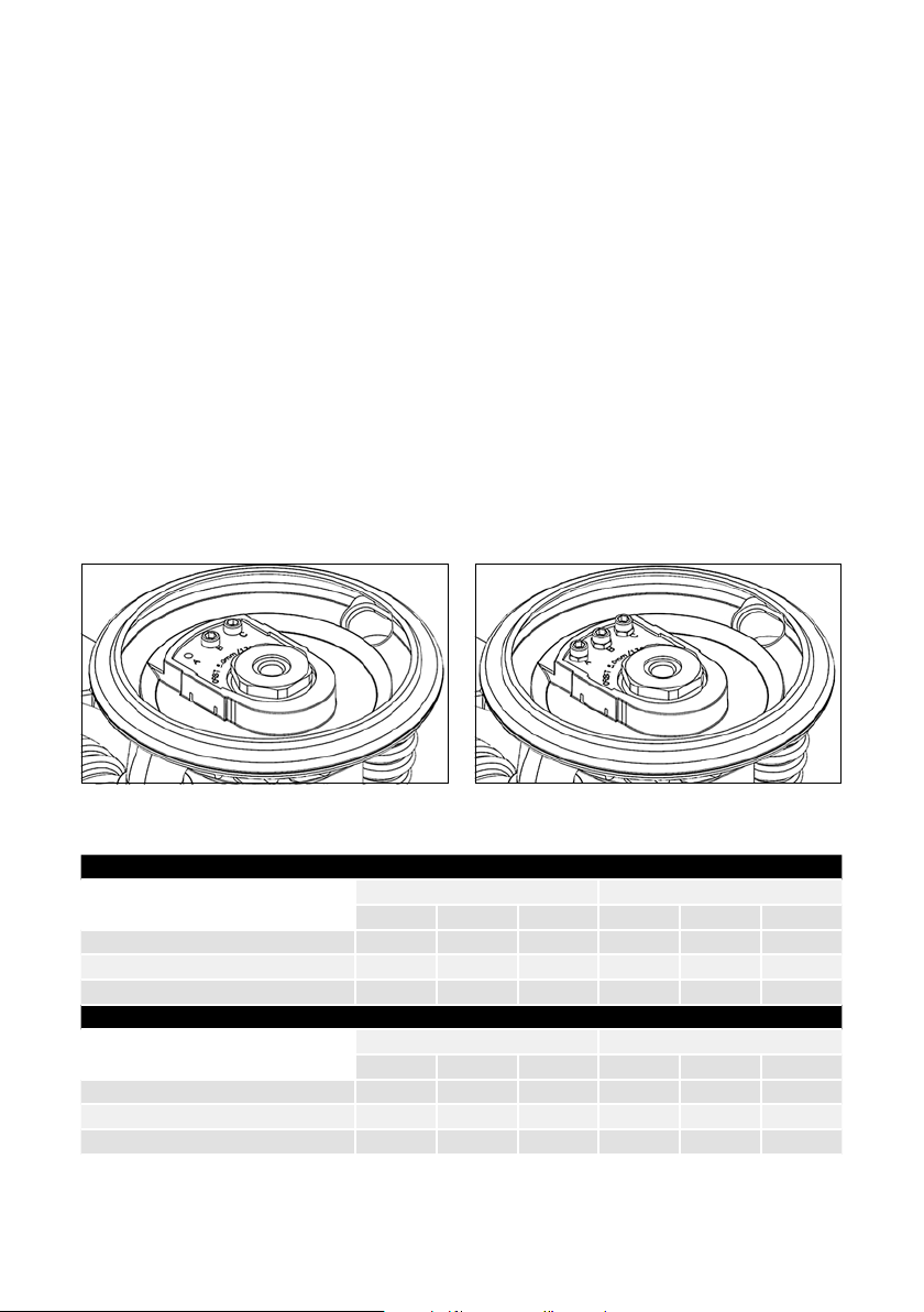
3. All six (6) M8 screw holes should be used to ensure a robust
connection. Note that the pivot pin location is at the front of the tool.
4. On the CV version: Connect the vacuum hose to the tool by fitting the
hose on the exhaust and twisting it counter-clockwise.
5. Connect the power cable to the tool by inserting and twisting the
connector counter-clockwise to the “lock” position.
Interfaces
FLANGE ISO 9409-1-80-6-M8
POWER CONNECTION Phoenix Contact ST-8EP1N8ACK04S
DUST HOSE CONNECTION 25 mm
Declaration of incorporation for partly completed machinery
In accordance with the EU Machinery Directive 2006/42/EC, Annex II, sub.B for partly completed machinery.
Manufacturer: Mirka Ltd
Address: Pensalavägen 210, 66850 Jeppo, Finland
Person established in the community authorised to compile the relevant technical documentation:
Annika Stenmark, Mirka Ltd
Description and identification of the partly completed machinery
Product / article: Mirka® AIROS 77 mm (3"), 125 mm (5") & 150 mm (6")
Type: 350CV, 350NV, 550CV, 550NV, 650CV, 650NV
Function: Grinding head
The following essential requirements of the Machinery Directive 2006/42/EC have been fulfilled:
1.3.2, 1.3.4, 1.3.7, 1.5.1, 1.5.4, 1.5.5, 1.5.9, 1.5.13
The relevant technical documentation is compiled in accordance with part B of Annex VII.
This partly completed machinery is in conformity of the following EU Directives:
EMC- Directive 2014/30/EU, RoHS- Directive 2011/65/EU
Applicable Harmonized Standards: EN 62841-2-4:2014, EN 61800-3:2004+A1:2012
The partly completed machinery must not be put into service until the final machinery into which it is to be
incorporated has been declared in conformity with the provisions of the Machinery Directive 2006/42, where
appropriate.
Jeppo 02.09.2019
Place and date of issue Stefan Sjöberg, CEO
Installing the tool
Connecting
the power
cable

4Mirka® AIROS • 77 mm (3"), 125 mm (5") & 150 mm (6") • Tool manual
Exploded view – Mirka® AIROS 350CV
èVisit www.mirka.com for details of spare parts.

4Mirka® AIROS • 77 mm (3"), 125 mm (5") & 150 mm (6") • Tool manual Mirka® AIROS • 77 mm (3"), 125 mm (5") & 150 mm (6") • Tool manual 5
Exploded view – Mirka® AIROS 350NV
èVisit www.mirka.com for details of spare parts.

6Mirka® AIROS • 77 mm (3"), 125 mm (5") & 150 mm (6") • Tool manual
Exploded view – Mirka® AIROS 650CV
èVisit www.mirka.com for details of spare parts.

6Mirka® AIROS • 77 mm (3"), 125 mm (5") & 150 mm (6") • Tool manual Mirka® AIROS • 77 mm (3"), 125 mm (5") & 150 mm (6") • Tool manual 7
Exploded view – Mirka® AIROS 650NV
èVisit www.mirka.com for details of spare parts.

8Mirka® AIROS • 77 mm (3"), 125 mm (5") & 150 mm (6") • Tool manual
Technical data
For Mirka industrial tool line-up
Mirka® AIROS 350CV 350NV 550CV 550NV 650CV 650NV
Rated voltage 48 VDC 48 VDC 48 VDC 48 VDC 48 VDC 48 VDC
Rated power 350 W 350 W 350 W 350 W 350 W 350 W
Speed 4,000–10,000 rpm 4,000–10,000 rpm 4,000–10,000 rpm 4,000–10,000 rpm 4,000–10,000 rpm 4,000–10,000 rpm
Orbit 5 mm 5 mm 5 mm 5 mm 5 mm 5 mm
Size (pad) 3" (77 mm) 3" (77 mm) 5" (125 mm) 5" (125 mm) 6" (150 mm) 6" (150 mm)
Tool offset (with
the included pad) 113 ± 1 mm 113 ± 1 mm 113 ± 1 mm 113 ± 1 mm 113 ± 1 mm 113 ± 1 mm
Weight 1.1 kg 1.1 kg 1.4 kg 1.4 kg 1.4 kg 1.4 kg
Degree of protection III III III III III III
Dust extraction Yes No Yes No Yes No
IP classification IP66 IP66 IP66 IP66 IP66 IP66
Sound pressure
level (LpA)––71 dB(A) 71 dB(A) 71 dB(A) 71 dB(A)
Sound power
level (LWA)––82 dB(A) 82 dB(A) 82 dB(A) 82 dB(A)
Sound measurement
uncertainty K – – 3 dB 3 dB 3 dB 3 dB
Maintenance
Always disconnect the power before carrying out
maintenance!
Only use original Mirka spare parts!
Replacing the backing pad
1. Insert the pad wrench between the backing pad and brake seal to hold the spindle nut.
2. Turn the backing pad counter-clockwise to remove it.
3. Fit and tighten the new backing pad with washers using the pad wrench.
4. Remove the pad wrench.
Replacing the brake seal
NOTE! Too much vacuum in your dust extraction system may cause the brake seal to lift up and malfunction.
1. Remove the backing pad as described above.
2. Pull the old brake seal out of its groove.
3. Fit the new brake seal in the groove.
4. Fit the backing pad as described above.
5. Check the brake seal function. By changing the number of washers between the spindle and backing pad, the
effect of the brake seal can be adjusted.

8Mirka® AIROS • 77 mm (3"), 125 mm (5") & 150 mm (6") • Tool manual Mirka® AIROS • 77 mm (3"), 125 mm (5") & 150 mm (6") • Tool manual 9
Replacing the spindle bearing
1. Remove the backing pad.
2. Remove the retaining ring. This is done by using a small flathead screwdriver to pry the retaining ring out of its
groove, then using a pair of pliers to pull the retaining ring out. The retaining ring is then discarded.
3. Grasp the spindle with pliers and pull it out of the bearing package. Pulling the bearing will create a partial
vacuum in the bearing chamber, which will result in some resistance. This pressure difference will gradually
equalise. Note: The backing pad can also be used to remove the spindle bearing, by fitting it back on and using it
to pull out the spindle.
4. Insert the new spindle bearing kit into the spindle chamber.
5. Insert the new retaining ring using a small flathead screwdriver. The ring should click in place.
6. Check if the spindle bearing is properly installed. The retaining ring should be in its designated groove and
should be able to rotate.
Reducing vibrations
When a pad saver or interface is used, the set-up may increase the level of vibrations. The tool has a feature that
allows you to reduce these vibrations. To reduce vibrations that may appear when a pad saver or interface is used,
please follow these steps:
1. Disconnect power cable.
2. Remove backing pad.
3. Add hex nuts and screws in accordance with the table below, tighten to 2 Nm.
Machine configuration out of the box Machine configuration for use with pad saver or interface
Model Picture Set-up out of box
Screw Hex nut
A B C A B C
350CV & 350NV – ––––––
550CV & 550NV – X X – – –
650CV & 650NV 1 – X X – – –
Model Picture Set-up for pad saver / interface*
Screw Hex nut
A B C A B C
350CV & 350NV – ––––––
550CV & 550NV XXXXXX
650CV & 650NV 2 XXXXXX
* The number of screws and/or hex nuts used is very dependent on the weight of the pad saver or interface
attached to the backing pad. A lighter pad saver might only need one screw to be added, while for a heavy
interface all of the nuts will be needed.

10 Mirka® AIROS • 77 mm (3"), 125 mm (5") & 150 mm (6") • Tool manual
Troubleshooting guide
Symptom Recommended procedures
The tool slows down in use. • Check the temperatures of the tool and the motor drive.
• Reduce the load on the tool.
• Check the condition of the spindle bearing.
Dust extraction is weak or
does not work.
• Check and replace brake seal.
• Check and replace dust hose.
The brake seal does not
work.
• Check and replace brake seal.

10 Mirka® AIROS • 77 mm (3"), 125 mm (5") & 150 mm (6") • Tool manual

Mirka Ltd
Finland
Brazil Mirka Brasil Ltda.
Belgium Mirka Belgium Logistics NV
Canada Mirka Canada Inc.
China Mirka Trading Shanghai Co., Ltd
Finland & Baltics Mirka Ltd
France Mirka France Sarl
Germany Mirka GmbH
India Mirka India Pvt Ltd
Italy Mirka Italia s.r.l., Cafro S.p.A.
Mexico Mirka Mexicana S.A. de C.V.
Russia Mirka Rus LLC
Singapore Mirka Asia Pacific Pte Ltd
Spain Mirka Ibérica S.A.U.
Sweden Mirka Scandinavia AB
Turkey Mirka Turkey Zımpara Ltd Şirketi
United Kingdom Mirka (UK) Ltd
United Arab Emirates Mirka Middle East FZCO
USA Mirka USA Inc.
For contact information,
please visit www.mirka.com
© Mirka Ltd 09/2019
Dedicated to the finish
This manual suits for next models
5
Table of contents
Other MIRKA Grinder manuals