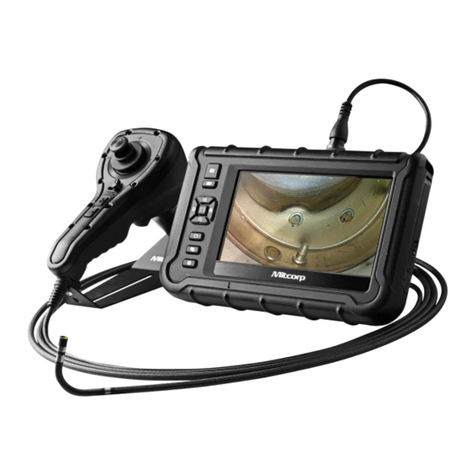
Mitcorp X750 User manual

Safety & Precautions
[Part I] Product
1.1 Scope of Delivery
1.2 X750 Overview
1.3 Brightness Control Button
1.4 Custom Hotkey Function Button
1.5 Snapshot
1.6 Video Recording
1.7 Articulation Joystick / Articulation Lock Switch
1.8 Battery Changing / Charging
1.9 Assembly/Disassembly / Handling & Care
1.9.1 Base Unit + Tube Unit Installation
1.9.2 Tube Unit + Probe Stand Installation
1.9.3 Battery Unit Installation
1.9.4 Shoulder Strap
1.9.5 Handling & Care
1.10 Roll – Up Tubes / Probe Stand
1.11 I/O Ports Connection
1.12 Secondary Camera / LED
[Part II] On Screen Display (OSD) functions
2.1 Live View screen UI
2.2 Function list
2.3 Full screen
2.4 Zoom In/Out
2.5 Album
2.6 Album – Photo annotation function
2.7 Album – Compare function
[Part III] Main MENU settings
3.1 MENU
3.2 WIRELESS FUNCTION
3.3 USB
3.4 SD CARD STATUS
4
7
7
8
9
9
10
10
11
12
13
13
15
16
17
17
19
20
21
21
21
22
25
25
25
27
29
31
31
32
33
34
[Table of Contents]

3.5 MICROPHONE
3.6 SESSION
3.7 TAG
3.8 WATERMARK
3.9 WHITE BALANCE
3.10 HOTKEY FUNCTIONS
3.11 OSD FUNCTIONS
3.12 TIME SETTING
3.13 LANGUAGE
3.14 INFO
Specications
Accessories
Appendices
Probable usage of GPS marks data of X750 images
X750 Basic Troubleshooting
34
35
36
40
41
43
44
45
45
46
48
50
51
52
54

Safety & Cautions
CE NOTICE
The Videoscope System is in conformance with the following standards:
• 2014/30/EU Electromagnetic Compatibility Directive.
The Videoscope System is in conformance with the requirements of the European law on
the Restriction of Hazardous Substances (RoHS) directive. This means that our product is
both lead-free and without the hazardous substances either in the manufacturing process
orinthenalproduct.RoHS NOTICE
FCC NOTICE
FEDERAL COMMUNICATIONS COMMISSION INTERFERENCE STATEMENT
This equipment has been tested and found to comply with the limits for a Class B
digital device, pursuant to part 15 of the FCC Rules. These limits are designed to
provide reasonable protection against harmful interference in a residential installation.
This equipment generates, uses and can radiate radio frequency energy and, if not
installed and used in accordance with the instructions, may cause harmful interference
to radio communications. However, there is no guarantee that interference will not
occur in a particular installation. If this equipment does cause harmful interference to
radio or television reception, which can be determined by turning the equipment off
and on, the user is encouraged to try to correct the interference by one or more of the
following measures:
-Reorient or relocate the receiving antenna.
-Increase the separation between the equipment and receiver.
-Connect the equipment into an outlet on a circuit different from that to which the
receiver is connected.
-Consult the dealer or an experienced radio/ TV technician for help.
CAUTION:
Any changes or modifications not expressly approved by the grantee of this device
could void the user's authority to operate the equipment.
RF Exposure Information (SAR)
This device meets the government’s requirements for exposure to radio waves. This
device is designed and manufactured not to exceed the emission limits for exposure to
radio frequency (RF) energy set by the Federal Communications Commission of the U.S.
Government.
The exposure standard employs a unit of measurement known as the Specific
Absorption Rate, or SAR. The SAR limit set by the FCC is 1.6 W/kg. Tests for SAR are
conducted using standard operating positions accepted by the FCC with the EUT
transmittingatthespeciedpowerlevelindifferentchannels.
- 4 -
Safety Conformances
USER MUST PAY ATTENTION TO THE INFORMATION PROVIDED HERE TO
ENSURE SAFETY.
We suggest you read the following statements carefully before using the system.
Iftheequipmentisusedinamannernotspeciedbythemanufacturer,theprotection
provided by the equipment may be impaired.
SAFETY GUIDE
WARNING
CAUTION
If this product is used without observing the information given under
this symbol, it might cause injuries or loss of life.
If this product is used without observing the information given under
this symbol, it might cause damage to this product.
WARNING
CAUTION
HAZARDOUS ENVIRONMENTS
• Do not use this system in explosive environments such as
gasoline or alcohol storage tanks.
FLAMMABLE GASES
• Donotusethissystemnearammablegases.
INDUSTRIAL USAGE ONLY
INTENSIVE LIGHT MAY CAUSE EYE INJURY
• Avoid looking at the probe head while LED is on.
CERTAIN SUBSTANCES MAY DAMAGE THE PROBE
• Please refer to the list of chemical resistances below. Contact
the store of purchase for further information on other
chemicals or unsure chemical solutions.
WARNING
WARNING
WARNING
Chemical Resistance
• Water
• Brakeuid
• Gasoline
• Diesel fuel
• Transmissionuid
• Risk of explosion if battery is replaced by an incorrect type.
• Dispose of used batteries according to the instructions.
CAUTION BATTERY
- 5 -
CAUTION

- 6 -
CAUTION Camera High Temperature warning
• Prevent using the camera head in an over 100°C environment.
• The base unit shows three levels (60°C/80°C/100°C) camera
temperature warning signals. Take out the tube when the
100°C warnings signal pops up.
Changing Probes/Base Unit
• MUST follow the “Basic Installation” instructions in the
manual and use proper tools to complete the concerned
operations.
CAUTION
CAUTION Recharging Battery
• use the original accessory charging units. Do not try
using any other electronic charger or recharging method for
the batteries.
Media Files Compatibility
• The media files captured and saved by the X750 system,
including photos and videos, are not compatible with any
other Mitcorp product.
• TheX750systemcannotreadmedialesfromanyother
Mitcorp product.
CAUTION
MUST

- 7 -
Part I Product
•1.1 Scope of Delivery
• Base Unit*1
• Probe Unit*1(Including Probe Stand)
• Battery Unit*2
• Charging Unit*1
• User Manual*1
• HDMI Cable*1
• USB cable*1
• USB Charging Adaptor*1
• Shoulder Strap*1
• Trolley Case*1
• Rigid Sleeve*1

- 8 -
•1.2X750Overview
16
7
8
2
13
12
11
6
10
3
4
9
1
5
15
No. Item No. Item
1 Function Buttons (1~3) 9 Probe Stand
2 Trigger Button 10 I/O Port(Right Side)
3 Articulation Joystick 11 I/O Port(Left Side)
4 Articulation Lock Switch 12 Secondary Camera
5Battery (Detachable) 13 LED Light
6 Base Unit 14 Power Indicator LED
7 Base Unit Connector 15 Ergonomic Handgrip
8 Shoulder Strap Handle 16 Tube Strain Relief
14

- 9 -
•1.3BrightnessControlButton
Press the <up>/<down> (button 1/button 2) to adjust the brightness. There
are 13 levels of brightness control:1-5->Tip LED light. 6-10->Exposure Value.
11-13->Exposure Time.
The X750 system provides live-view focus exposure gain control to get rid of
glaresandreections(suchasonmetalsurfaces…,etc).
Tap the glare spot on the screen; the system will auto-tune to optimize the
image brightness. Tapping a dark area will increase image brightness (higher
exposure gain value).
Ps. the gain control dynamic range is conditionally constrained.
•1.4CustomHotkeyFunctionButton
Round button 3 on the handgrip allows setting up hotkey functions from the
setting menu. Default:
• Short pressing the button: Switch the back light LED ON/OFF.
• Long pressing the button: Freeze the Image.

- 10 -
•1.5Snapshot
Short press the [Trigger] button. Timestamp/Logo Watermark/Grid will be
recorded on the photo when enabled.
•1.6VideoRecording
Long press the [Trigger] button to start/stop recording the video.
During recording, short press the [Trigger] button can take and save the real-
time screenshot photo.

- 11 -
•1.7ArticulationJoystick/ArticulationLockSwitch
The articulation joystick allows for easy maneuvering the probes.
1. Moving the joystick handle into the desired direction will prompt the probe
to articulate.
The articulation lock switch can be found below the joystick.
2. Flip the switch to the right to enable the lock.
3. A clicking sound will indicate successful articulation lock.
4. The probe will be locked in place after releasing the joystick.
CAUTION: Release the articulation lock by flipping the switch to the left
before removing the probe from an object to avoid damage.

•1.8BatteryChanging/Charging
1 Press and hold the bottom robber mark to unload the battery.
2 Insert the battery into the charging dock and connect to the power socket
with the attached USB cable and adaptor. Notice the latch click feedback
when the insertion was successful.
3 Reload a full recharged battery into the X750 handgrip set.
Ps. The 2 slots charging dock is equipped with an independent LED charging
indicator.
Green light: Power on / Full charged.
Orange light: Charging / Battery partial full.
Notice: When the battery is unloaded, the system time setting will be reset
to default. Remember to set up correct date and time every time you
change battery.
- 12 -

•1.9Assembly/Disassembly/Handling&Care
1.9.1 Base Unit + Tube Unit Installation
1. Place the Probe Stand upright.
2. Place the base unit on the base unit connector on the articulation probe.
- 13 -

3. Fasten the screw
CAUTION: Do not remove the screw from the probe stand.
Be careful to not overtighten the screw.
Always use a screwdriver to fasten screws.
- 14 -

1.9.2 Tube Unit + Probe Stand Installation
1. Carefully lift up the articulation probe.
2. Move the Probe Stand along the articulation probe towards the probe
strain relief.
3. Align the Probe Stand’s screw with the connector on the articulation probe
(the long side of the stand must face inwards toward the battery release
of the probe).
4. Carefully tighten the screw.
CAUTION: Do not remove the screw from the probe stand.
Be careful to not overtighten the screw.
Always use a screwdriver to fasten screws.
- 15 -

1.9.3 Battery Unit Installation
1. To remove the batteries carefully squeeze the top of the batteries
lengthwise
2 Slowly pull to remove the battery from the X750
3 Place the battery back in the charging station
4 Repeat the process and push the new battery into the battery holder of
the X750
- 16 -

1.9.4 Shoulder Strap
1.9.5 Handling & Care
CAUTION:
1. Always store the insertion probes, the base unit and the batteries properly
- 17 -
To Storage
Keep at least 35 cm diameter circle Using packing standard cushion to tangle tube

- 18 -
2. Do not roll the probes up too tightly (aim for a diameter of at least 15cm)

Put down the holder and let the tube hang on to it. Insert the tip end and
bendingneckthroughtheholderholeabove20cm.Thetubecanbexed.
• 1.10 Roll – Up Tubes / Probe Stand
Lift up the probe holder and pass through the rolling tube.
- 19 -

•1.11I/OPortsConnection
I/O Port
-Right Side
USB Type-C →Use the accessory or compatible USB cable.
→When connected to PCs, choose output: (1)
SD card reader; (2) Camera. Download &
install the “UsbVideoScope” software from
Mitcorp website to hire remote control of
the system.
→When connected to a USB power adaptor
can act as a power supply for real-time
operations (low recharging effect)
Reset Stab with a blunt pin when the system
accidentally crashes.
Power Indicator Green / Red
The indicator will show:
Green – When the device is turned on / fully
charged
Red – When the device is charging
I/O Port
-Left Side
HDMI Type-D →Use the accessory or compatible HDMI
cable.
→The system can output the live view
and saved images when connecting to
monitors/TVs.
→The touch screen function buttons of two
sides won’t be output and keep on the unit
screen during operations.
→Live view image won’t keep on-screen
during output operations.
→When playing back album photos & videos,
images will keep on-screen during output
operations.
Micro SD
Push-push type micro SD card slot. Install the
SDcardbyconnectingthengersideup.
When covering the outside robber cover,
please avoid hard push to this position. Just
push stoppers around the cover.
- 20 -
Table of contents
Other Mitcorp Analytical Instrument manuals