Southland OMD-625 User manual

Designed, Tested and Assembled in California, USA
OMD-625 Rev 1.12 August 20th, 2020_BB
OMD-625 Oxygen Analyzer
Input Power: 12 - 24V DC
OMD-625 Oxygen Analyzer
Instruction Manual
OMD-625 Oxygen Analyzer
Instruction Manual

Table of Contents
OMD-625 Oxygen Analyzer
Designed, Tested and Assembled in California, USA
Part 1 Introduction
Part 2 Installation
Part 3 Operation
Part 5 Annexures
Part 4 Maintenance
1.1 General Introduction
1.2 Principle Of Operation ‘The Oxygen Sensor’
1.3 OMD-625Specications
1.4 General Safety & Installation Guidelines
1.5 Location Installation Considerations
1.6 Safety Considerations
2.1 Receiving Your New Oxygen Analyzer
2.2 Mounting The Oxygen Analyzer
2.3 Electrical Connections
2.4 Gas Connections
2.5 Installing The Oxygen Sensor
2.6 Integral Sample System Flow Diagram
2.7 Sensor Selection (TO2-133 vs. TO2-233)
3.1 Understanding The Controls And Their Operation
3.2 Manual Range Output Selection (Locks Analog Output)
3.3 Custom Range Option (i.e. 0 - 93.4ppm Full Scale)
3.4 Analog Output 4 - 20mA (1 - 5V DC Optional)
3.5 Analog Output Adjustment (4mA and 20mA)
3.6 Analog Output Simulation (4mA, 8mA, 12mA, 16mA, 20mA)
3.7 AlarmConguration
4.1 Span Calibration Using Ambient Air
4.2 SpanCalibrationUsingCertiedSpanGas
4.3 Procedure For Replacing The Oxygen Sensor
4.4 Troubleshooting
4.5 Zero Calibration
5.1 Spare Parts List
5.2 Warranty
5.3 Material Safety Data Sheets
5.4 ConformanceCerticate

1.1 General Introduction
The Southland Sensing OMD-625 Oxygen Analyzer is a microprocessor based online unit designed for
continuous measurements in a variety of applications and gas mixtures.
The analyzer was designed with the customer in mind keeping the operations simple, while still featur-
ing a fast response and rugged design. Every eort has been made to use modern industrial compo-
nents and materials which has resulted in an advanced design, excellent performance and an overall
low cost of ownership.
The analyzer has numerous options including PPM, Percent and Purity oxygen analysis. The unit can
also be congured with or without MODBUS meeting most oxygen analysis applications.
Southland Sensing Ltd. appreciates your business and recommends to read through the complete
manual to be able to get the full experience from your new oxygen transmitter.
1.2 Principle of Operation - The Oxygen Sensor
The precision electrochemical oxygen sensor used in the OMD-625 is designed and manufactured by
Southland Sensing Ltd under a strict quality procedure.
To understand how the oxygen analyzer functions, it is important to understand a little bit of the sen-
sor characteristics.
The active components in the precision electrochemical oxygen sensor are the anode, cathode and
aqueous electrolyte which are all housed in a cell body. The oxygen molecules in the application pass
through the front sensing membrane. A chemical reaction occurs and a raw electrical current is gen-
erated.
This electrical current is proportional to the amount of oxygen in the application. The analyzer then
processes this raw electronic signal, compensates for temperature and barometric pressure varia-
tions and converts the data into a parts-per-billion, parts-per-million or percent oxygen measurement
value.
The oxygen concentration reading is then displayed on the local display and output to the various
analog and digital outputs features in the analyzer.
Introduction
OMD-625 Oxygen Analyzer
Precision Electrochemical Oxygen Sensor
Designed, Tested and Assembled in California, USA
4045 E. Guasti Rd. #203 Ontario, CA 91761 USA : 1-949-398-2879 : [email protected] : www.sso2.com

Designed for the Natural Gas Industry
Class 1, Div 1 Groups B, C, D
Custom Full Scale Range (i.e. 0 - 99 ppm)
Precision Fuel Cell Oxygen Sensor Technology
Large Backlight Display
Ability to Calibrate Analog Output
Measure Oxygen from 0.01ppm to 25%
Intuitive User Friendly Interface
Cost Eective and Low Maintenance
2 Congurable Alarm Relay Contacts
Output Sim (4mA, 8mA, 12mA, 16mA and 20mA)
Specications:
Accuracy: < +/-1% Full Scale Range*
Alarms: 2 Congurable Relay Contacts
Analyzer Range: 0 - 10/100/1000/10000ppm/25%
Optional Range 1: 0 - 1%,/5%/10%/25%/100%
Area Classication: Class 1, Div 1, Groups B,C,D
Dimensions: 15.25” x 12.5” x 5.25”
Flow: 0.25 - 5.0 SCFH
Gas Connections: 1/4” Compression Tube
Output: Isolated 4 - 20mA or 1 - 5 VDC
Power: 12 - 24 VDC
Pressure 0.1 - 50 PSIG Inlet, vent to atm
Response Time: T90 in 10 Seconds
Sensor: Precision Fuel Cell
Temperature: -10 to 50 deg C
Warranty Sensor: 12 Months
Warranty Electronics: 12 Months
Weight: 18.5 lbs
*Accuracy at constant conditions
Applications:
“Inquiry for Application Expertise”
• Natural Gas Extraction & Pipelines
• Natural Gas Processing
• Acid (CO2) Gas Streams
• Inert, Hydrocarbon, Hydrogen Processing
• And Many Other Industrial Applications
Optional Congurations:
- Sample System Add-On Components
- Bi-Directional RS485 Modbus RTU
- Extreme Weather Packaging w/ Heater
Product Specication Sheet
OMD-625 Oxygen Analyzer
Hazardous Area Online Process Oxygen Analyzer w/Sample System
Designed, Tested and Assembled in California, USA
4045 E. Guasti Rd. #203 Ontario, CA 91761 USA : 1-949-398-2879 : [email protected] : www.sso2.com
Rev 1.12 August 27, 2020_BB

OMD-625 Oxygen Analyzer Product Specications
Oxygen Analyzer: Oxygen Sensor Technology:
Order Information:
Oxygen Sensors:
Record Part Number with selected options in Blank Indicated Area of Form
Model Number:
OMD-625 Oxygen Analyzer
OMD-625D Oxygen Analyzer (Delete Sample System, 1/8” Compression Tube Gas Inlets)
Selected Range & Sensor:
3T Trace Analysis Standard (TO2-133): 0 - 10ppm, 0 - 100ppm, 0 - 1000ppm, 0 - 10000 PPM 0 - 25%
4T Trace Analysis Standard (TO2-233): 0 - 10ppm, 0 - 100ppm, 0 - 1000ppm, 0 - 10000 PPM 0 - 25%
5T Trace Analysis < 500 PPM H2S (TO2-238): 0 - 10ppm, 0 - 100ppm, 0 - 1000ppm, 0 - 10000 PPM 0 - 25%
5P Percent Analysis Standard (PO2-160): 0 - 1%, 0 - 5%, 0 - 10%, 0 - 25%, 0 - 100%
6P Percent Analysis Standard (PO2-24): 0 - 1%, 0 - 5%, 0 - 10%, 0 - 25%, 0 - 100%
Electronics Package:
2 12 - 24V DC 2-wire Loop (delete backlight, delete alarm relay contacts)
4 12 - 24V DC 4-wire Input Power
7 100 - 240V AC Input Power
M 12 - 24V DC Input Power w/ Bi-Directional MODBUS RS485 RTU
OMD-625 - - -
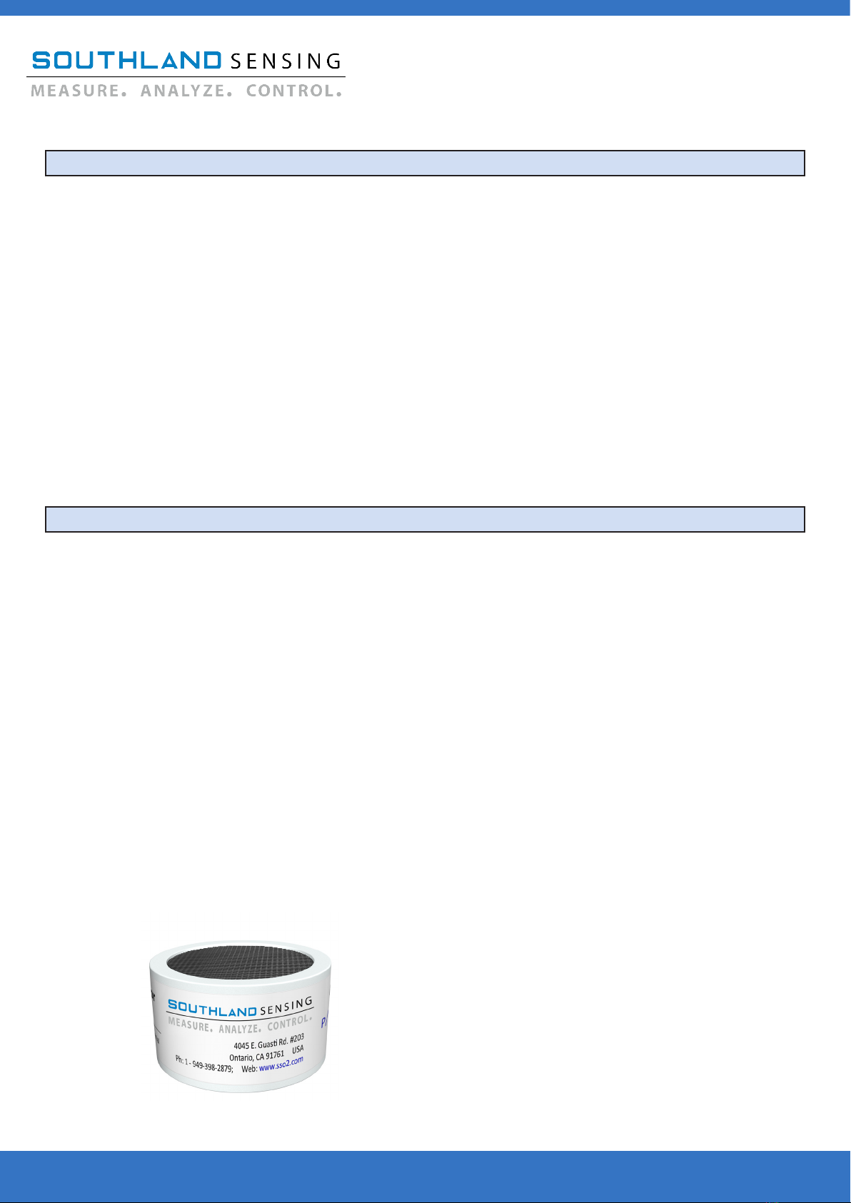
The oxygen sensor used in the OMD-625 is based on the
galvanic electrochemical fuel cell principal. All oxygen sensors
are manufactured in house by Southland Sensing Ltd. under a
strict quality program.
The standard cells are unaected by other background gases
such as H2, He or Hydrocarbons. The acidic cells work well
when acid gases such as CO2 or natural gas are present.
The sensors are self-contained and minimal maintenance is
required - no need to clean electrodes or add electrolyte.
The SSO2 precision oxygen sensors oer excellent perfor-
mance, accuracy and stability while maximizing the expected
life.
TO2-133 PPM Oxygen Sensor: Trace Analysis, Standard
TO2-233 PPM Oxygen Sensor: Trace Analysis, Acidic
TO2-238 PPM Oxygen Sensor: Trace Analysis, < 500PPM H2S
PO2-160 Percent Oxygen Sensor: Percent Analysis, Standard
PO2-24 Percent Oxygen Sensor: Percent Analysis, Acidic
Oxygen sensors should be periodically calibrated. Factory
recommendation is every 2 - 3 months or as the application
dictates. Sensors oer excellent linearity with an air calibra-
tion, or calibrate to a certied span gas to maximize accuracy.
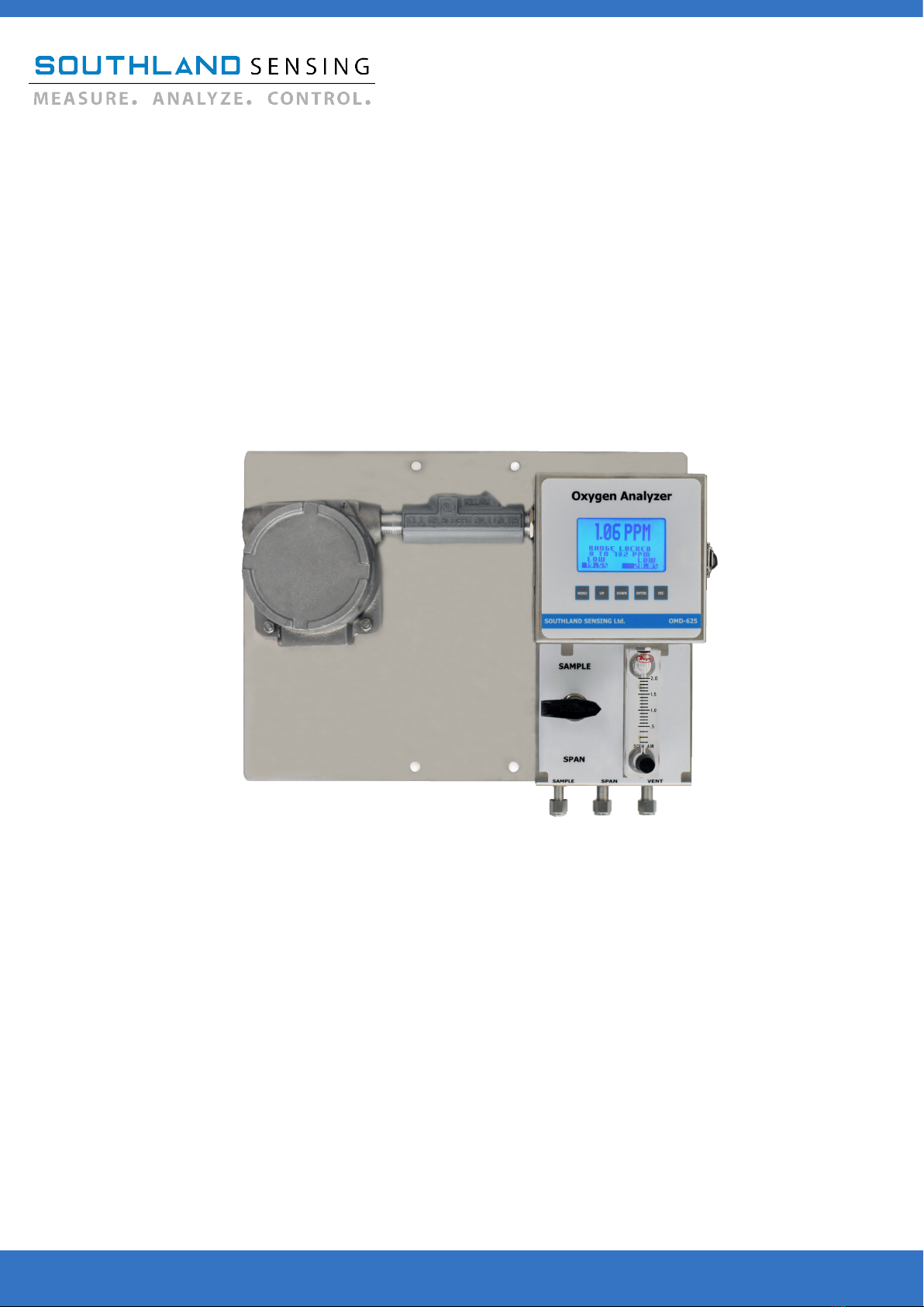
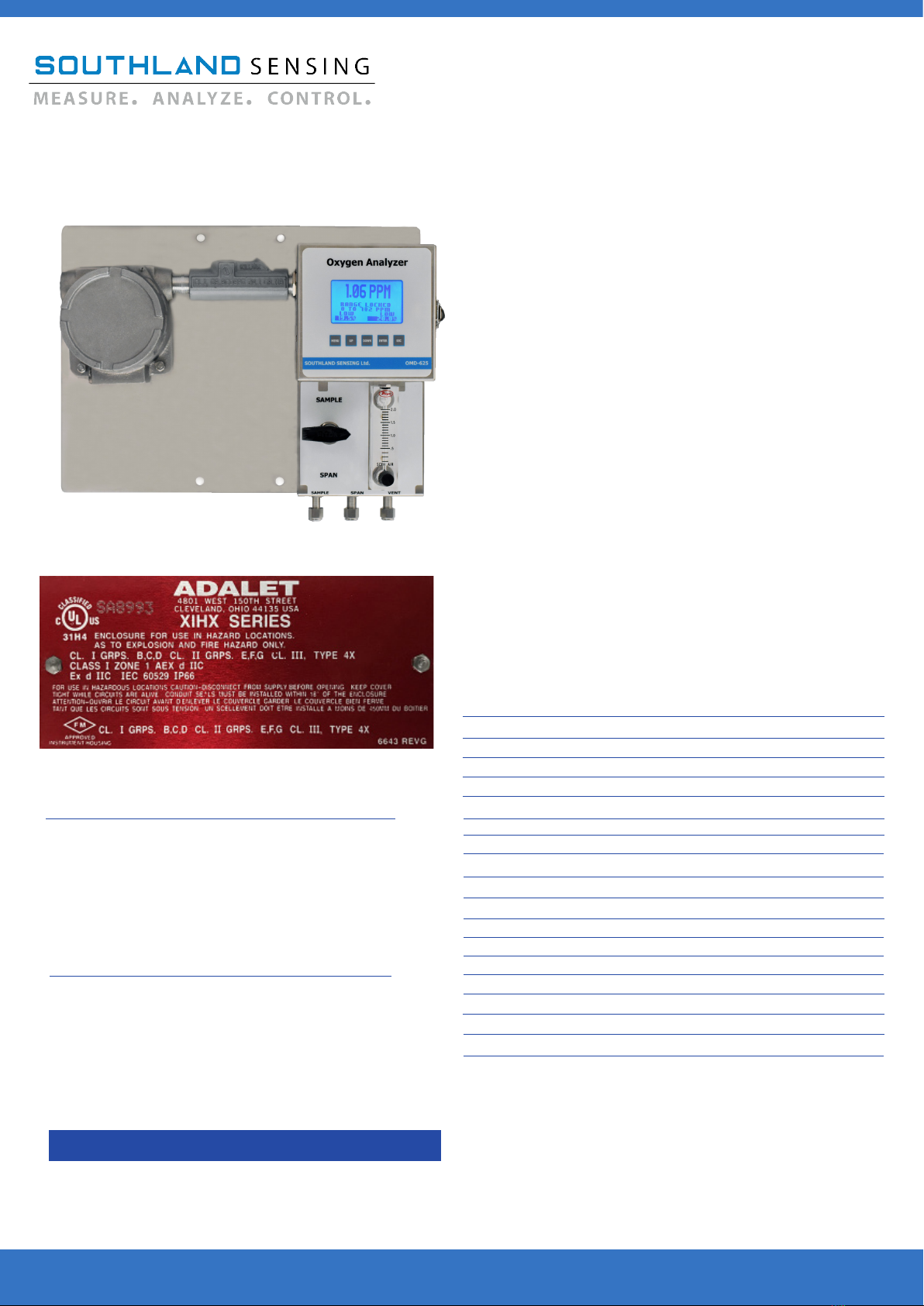
The model OMD-625 oxygen analyzer combines a
rugged design with SSO2’s precision oxygen sen-
sors. The result is a highly reliable and cost eec-
tive compact design with easy-to-use user interface
designed specically for the natural gas industry.
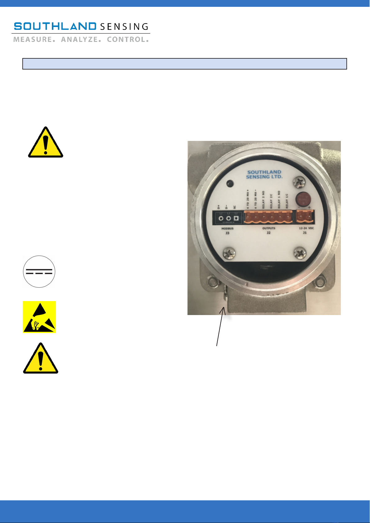
The oxygen analyzer is designed to meet standards
for Class 1, Div 1, Groups B, C, D installation.
The oxygen analyzer is isolated both on the power
input and analog output. This eliminates most
electronic gremlins seen with existing competitive
equipment in the eld.
Standard ranges include 0 - 10ppm, 0 - 100ppm, 0 -
1000ppm, 0 - 10000ppm, 0 - 25%.
Optional Percent Analysis Ranges: 0 - 1%, 0 - 5%,
0 - 10%, 0 - 25%, 0 - 100%.
Custom Range: The unit comes with the ability to
customize a 6th range (i.e. 0 - 94 ppm).
Standard Power Requirements:
Gas Connections:
4 1/4” Compression Tube Fittings
6 6mm Compression Tube Fittings
8 1/8” Compression Tube Fittings
Input Power: 12 - 24 V DC
Current Draw: 50 mA
** Optional power input choices available
Use This Part Number When Ordering
Designed, Tested and Assembled in California, USA
Rev 1.12 August 27, 2020_BB

Introduction
OMD-625 Oxygen Analyzer
Designed, Tested and Assembled in California, USA
1.4 General Safety & Installation
This section summarizes the precautions applicable to the OMD-625 Oxygen Analyzer. Additional pre-
cautions specic to this analyzer are contained in the following sections of the manual. To operate the
analyzer safely and to obtain the best performance, follow the basic guidelines outlined in this owner’s
manual.
CAUTION:
WARNING:
CAUTION:
This symbol is used throughout the owner’s manual to warn and alert
the user of the presence of electrostatic discharge.
This symbol is used throughout the owner’s manual to caution and
alert the user to recommended safety and / or operating guidelines.
This symbol is used throughout the owner’s manual to caution and alert
the user that this device is operated on Direct Current Voltage (VDC).
READ INSTRUCTIONS: Before operating the oxygen analyzer, read the instructions.
RETAIN INSTRUCTIONS: The safety precautions and operating instructions found in the owner’s
manual should be retained for future reference.
FOLLOW INSTRUCTIONS: Observe all precautions and operating instructions. Failure to do so
may result in personal injury or damage to the transmitter.
OXYGEN ANALYZER LABEL:
Model Number: OMD-625
Serial Number: 0036785
Oxygen Analyzer
Voltage: 12 - 24 VDC
Max Current: 100 mA
4045 E. Guasti Rd. #203 Ontario, CA 91761 USA
Ph: (949) 398-2879 Web: www.sso2.com

The Southland Sensing OMD-625 Oxygen Analyzer is designed to be mounted on a wall or on a pipe
in a general purpose, Class 1 Division 1 or Class 1 Division 2 Group B, C, D area. When installed out-
doors in cold areas an optional heater is recommended as well as a heavy duty enclosure. Consider
also giving the analyzer a sun shield if it is going to be mounted in the direct sunlight.
Seals are required on the power and signal condulet entries, whether the area classication is Division
1 or Division 2. Reference your local electrical authority for the proper installation.
The analyzer is EMI / RFI protected, however it is good practice not to mount it too close to sources
of electrical interference such as large transformers, motor start contactors, relays, large pumps, etc.
Also, avoid subjecting the analyzer to signicant vibration.
The analyzer has a local display, mount the unit at a suitable eye level for easy reading. Gas connec-
tions are located on the bottom of the analyzer, make sure there is room to hook up your gas lines.
The oxygen analyzer is designed for installation into either a general purpose area, or a Class 1 Divi-
sion 1 or a Class 1 Division 2 Group B, C, D area, but it is also designed so that a hazardous gas may
be introduced into the main sensing compartment. This gas may be of any group B, C or D.
The analyzer consists of two enclosures mounted on a single back panel. The small round enclosure
is explosion-proof and contains the electrical connections for the user - such as power, alarms and
analog output (Optional MODBUS). This explosion-proof enclosure also contains the power supply
and safety components for the other enclosure. The larger square enclosure contains the analytical
circuitry, the oxygen sensor and the oxygen sensor housing. This circuitry is designed for intrinsic
safety and meets requirements for Class 1 Division 1 Group B, C, D.
When installing a Class 1 Division 1 or Class 1 Division 2 device, please follow your local electrical
code should the area need to be declassied prior to installation.
Introduction
OMD-625 Oxygen Analyzer
1.5 Location Installation Considerations
1.6 Safety Considerations
Designed, Tested and Assembled in California, USA

As soon as you receive your new Oxygen Analyzer, carefully unpack the unit and accessories and inspect
the electronics module, sensor housing for damage and also verify the oxygen sensor is present.
CAUTION: Do not open the oxygen sensor packaging at this time. It is packed in a Nitrogen
purged bag and will be damaged if left exposed to ambient air for a prolonged period of time. It is
recommended that you read through the instruction manual installation and operation sections before at-
tempting to open the bag the oxygen sensor is packed in. For questions, please contact the factory.
If damage to any portion of the new analyzer is present, stop and report damage to the shipping com-
pany as well as the factory.
The analyzer is shipped with all materials needed to install and prepare the system for operation. In
some instances, added sample system components are necessary to condition the gas sample before en-
tering the sensor housing. Southland Sensing oers free application consultation, and we encourage you
to take advantage of our engineers and their expertise.
If installing into a Class 1 Div 1 or Class 1 Div 2 area, additional seals are needed for the power and sig-
nal condulet. These will need to be sourced locally and should meet your local electrical authority.
It is also important to be mindful of EMI / RFI noise interference. Protection from EMI / RFI noise is im-
portant for accurate readings.
2.1 Receiving your New Oxygen Analyzer
Installation
OMD-625 Oxygen Analyzer
Designed, Tested and Assembled in California, USA

The OMD-625 is designed to be mounted on a wall or around a pipe. When installing outdoors in an
extreme environment, consider an enclosure and heater if necessary. Consult the factory for recommen-
dations.
Refer to part 3 operation section of this instruction manual for more information on how to operate the
controls of this oxygen analyzer
Refer to part 4 maintenance section for an overview on how to calibrate the device using a certied span
gas or ambient air.
A precision electrochemical oxygen sensor is included as a separate item and must be installed prior to
instrument use.
CAUTION: Do not open the N2 lled oxygen sensor bag until you have thoroughly read the in-
struction manual and have made all gas and electrical connections. Please refer to section 2.4
2.2 Mounting The Oxygen Analyzer
Installation
OMD-625 Oxygen Analyzer
Designed, Tested and Assembled in California, USA

Incoming power/signal output
connections are made to the orange
terminal block located on the right
side of the connectors, labelled J1
Do no supply voltage more than specied in
this manual and noted on the analyzer label
inside of the unit.
Shielded cable is recommended when connect-
ing power and signal output.
Proper seals are recommended for the condulet
when bringing power into or signal out of the
explosion-proof portion of the analyzer.
Voltage: 12 - 24 VDC (Direct Current)
Max Current: 100mA
Avoid electrostatic discharge
If the analyzer is being installed
into a class 1 division 1 or class
1 division 2 area, the area will
most likely need to be declas-
sied prior to removing the round cap on the
explosion proof portion of the analyzer. Follow
your local electrical authority for proper proce-
dure.
It is also recommended to make sure you have
the proper seals for your condulet to meet your
required area classication. Check with your
local electrical authority.
For the OMD-625 Oxygen Analyzer, power, alarms and analog output is housed in the round explosion
proof enclosure on the left side of the panel. To access the circuit board, rst determine if your area
needs to be declassied and second remove the round enclosure top. Once removed you will have ac-
cess to the J1 and J2 connectors which are the Power (J1) and Alarms / Analog output (J2).
Analyzer ground terminal must be connected
to a ground.
Designed, Tested and Assembled in California, USA
2.3 Electrical Connections
Installation
OMD-625 Oxygen Analyzer

The OMD-625 can accept either a TO2-133 or TO2-233 (CO2 Applications - Natural Gas) oxygen sensor for
trace oxygen analysis. For Percent measurement, the OMD-625 can accept either a PO2-160 or PO2-24
(CO2 Applications - Natural Gas) oxygen sensor. For help selecting a sensor, contact your local sales rep
or the factory.
Prior to installing the sensor, it is important to make sure that the analyzer gas lines are hooked up and
the unit is ready to purge with a zero or process gas. Connect the zero gas line and set your ow be-
tween 0.25 - 2.0 SCFH.
To Install the Sensor:
- Open up the square enclosure which will give you access to the sensor housing.
- Remove the cell holder cap by unscrewing the stainless steel collar.
- Lift up on the top of the sensor housing and set to the side.
- Inspect O’ring for cracking, replace if necessary. Always lube your O’rings!
- Remove the sensor from its box. With scissors, open nitrogen purged packaging
and remove the sensor.
- Visually inspect sensor for damage, if damaged notify the factory immediately.
- Remove the shorting tab across the back of the sensor circuit board (red tape).
- Place the sensor inside the housing with the metal screen mesh facing down and
the circuit board contacts facing up.
- Return upper portion of the sensor housing to the stainless steel bottom. Tighten
collar. Hand tight is acceptable to create an airtight seal.
- Immediately start purge of zero gas.
- If the analyzer has not been calibrating, refer to section 4.1 for more information.
** Sensor should be exposed to ambient air for no more than 2 minutes. Extended periods of exposure
can damage the low end sensitivity and response time.
CAUTION: Prior to installing the oxygen sensor. Read section 4.1 on performing a
span calibration.
Oxygen Sensor Front and Rear View
Gas Connections are made via 1/4” Compression Tube Fittings. The gas connections are located below
the sample system on the bottom right. Sample connection is designed for your process gas. Span con-
nection is designed if you are using a certied bottle of calibration gas (optional). Vent is the outlet, typi-
cally designed to vent to atmosphere, a are stack or per your local regulations.
Designed, Tested and Assembled in California, USA
4045 E. Guasti Rd. #203 Ontario, CA 91761 USA : 1-949-398-2879 : [email protected] : www.sso2.com
2.4 Gas Connections
Installation
OMD-625 Oxygen Analyzer
2.5 Installing the Oxygen Sensor

Southland Sensing Ltd. strives to select the highest quality sample system components in the market.
All gas connections are made via compression tube ttings. Our valves are high quality leak tight which
we rigorously test in our environmental chamber. Our ow indicators / ow meters are from Dwyer, an
industry recognized leader in ow control When dealing with critical applications such as petrochemical
processing and natural gas extraction, we want to make sure we can deliver a high quality sample system
and we do so by partnering with some of the best brands in the market.
Along with our standard sample system as shown below, we can also custom design sample systems to
meet unique applications including the additional of moisture lters, pressure regulators, H2S scrubbers.
For more information on a custom solution for your application, please contact your local distributor or the
factor.
Sample In:
Span In:
Vent:
Sensor
Housing
3-Way
Valve
Flow
Meter
Designed, Tested and Assembled in California, USA
4045 E. Guasti Rd. #203 Ontario, CA 91761 USA : 1-949-398-2879 : [email protected] : www.sso2.com
2.6 Integral Sample System Flow Diagram
Installation
OMD-625 Oxygen Analyzer

The OMD-625 is typically shipped with a TO2-133 or TO2-233 PPM Oxygen Sensor. The TO2-133 is de-
signed with a base electrolyte for maximum performance in gases such as measuring oxygen in nitrogen,
argon or hydrogen. The TO2-233 is designed with an acid electrolyte and is congured for maximum
performance while measuring oxygen in CO2 and natural gas.
The TO2-133 and TO2-233 have dierent outputs, so it is important to setup the oxygen analyzer for the
specic oxygen sensor. This can be done with a quick selection in the user friendly MENU. This option
can be found as follows: MENU --> SYSTEM --> SENSOR TYPE --> TO2-133 or TO2-233 --> ENTER
This conguration is normally completed at the factory, but is available to the user should they decide to
switch sensors in the eld.
CAUTION: Do not open the oxygen sensor packaging at this time. It is packed in a Nitrogen
purged bag and will be damaged if left exposed to ambient air for a prolonged period of time. It is
recommended that you read through the instruction manual installation and operation sections before
attempting to open the bag the oxygen sensor is packed in. For questions, please contact the factory. If
you are not sure which sensor you have, look at the outside packaging and it will be labelled.
2.7 Sensor Selection (TO2-133 vs. TO2-233)
Installation
OMD-625 Oxygen Analyzer
Designed, Tested and Assembled in California, USA

The OMD-625 Oxygen Analyzer is a feature packed unit with an easy to use menu interface. The key
attributes within the menu are the ability to select a measurement range - including customizing your
own range (i.e. 0 - 93.5 ppm) or set the analyzer to a single manual range or auto-range mode. To
calibrate the unit with a known gas, also referred to as a SPAN Calibration or SPAN CAL., to perform
a ZERO Calibration (if necessary, most applications it is not required) and to set the alarm relays and
their functionality.
All features are programmable / selectable through the MENU button. The UP / DOWN arrows will
allow you to select your set points and the enter button saves the data. If you want to cancel your
selection, or return to the previous screen the escape key ESC will allow you to do this. Once the
unit starts up, the following HOME Screen will appear:
Operating Range
Current Oxygen Reading
Identier, Manual
or Auto Range
Alarm 2Alarm 1
3.1 Understanding The Controls And Their Operation
Operation
OMD-625 Oxygen Analyzer
Designed, Tested and Assembled in California, USA

The OMD-625 oxygen analyzer allows the user to eld select 5 available ranges - custom ranges are
available for the user to congure in the eld. These ranges can be selected in manual mode mean-
ing they are locked into that range by the user - which locks in the analog output, or they can be set
to auto-range so the analyzer will adjust itself as the readings change. Most applications will manu-
ally select a range so the output is locked and can be read by a PLC or DCS system.
One feature to highlight when using the Manual-Range mode, while selecting the Manual Range, this
is locking the 4 - 20mA output to a single range. The display will continue to operate in auto-range
mode giving the user the full spectrum of oxygen analysis. Other manufactures lock the display as
well, the problem is if you over-range and the display is locked, you have no idea what your O2 value
is. With the OMD-625, it answers this issue with a display that auto-ranges and the ability to manu-
ally lock the analog outputs.
To select Auto-Range or Manual-Range Mode, From the HOME screen, press the MENU key and the
display will indicate:
Use the UP / DOWN keys to move the cursor to allow the user
select AUTO-RANGE which will all the unit to cycle through all
ve ranges or MANUAL RANGE which will allow the user to
select a key range.
Decide which option will work best for your application.
Move the cursor button over the selection and press the
ENTER key. If you have selected the AUTO RANGE option,
it will blink for a second indicating this was selected. If you
selected the MANUAL RANGE option, the following screen
will be brought up:
Standard Ranges: 0 - 10ppm, 0 - 100ppm, 0 - 1000ppm, 0 - 10000ppm
and 0 - 25%
Optional Percent Ranges: 0 - 1%, 0 - 5%, 0 - 10%, 0 - 25%, 0 - 100%
User congurable range is the *6th Range* shown and is set as
default to 0 - 950 PPM. To change the value, proceed to section
3.3 “Custom Range Option” for step-by-step instructions.
Use the UP / DOWN keys and bring the cursor to the range to be selected and press the ENTER key.
The selected range will now be shown on the HOME page and RANGE LOCKED text will be highlight-
ed above it.
3.2 Manual Range Output Selection
Operation
OMD-625 Oxygen Analyzer
Designed, Tested and Assembled in California, USA
4045 E. Guasti Rd. #203 Ontario, CA 91761 USA : 1-949-398-2879 : [email protected] : www.sso2.com
MANUAL RANGE
0 - 25%
0 - 10000 PPM
0 - 1000 PPM
0 - 100 PPM
0 - 10 PPM
0 - 950 PPM
MAIN MENU
AUTO RANGE
MANUAL RANGE
SPAN CAL
ZERO CAL
ALARM 1
ALARM 2
SYSTEM

The OMD-625 oxygen analyzer gives the users the exible to select a full scale range to better match
the application they are working with. For example these can be basic such as 0 - 200 ppm or can
be a bit more exotic such as 0 - 93.2 ppm.
To congure a custom range option, enter the MENU --> SYSTEM --> CUSTOM RANGE. From here,
the user can use the UP or DOWN arrows to customize the upper end of the full scale range such as
0 - 200 ppm or 0 - 93.2 ppm. Once the value is correct hit ENTER to store the custom range.
Once the value is stored, the user will now need to select the manual range option 6 in the MANUAL
RANGE mode to lock the analog output to the new custom range. This can be done by going to
MENU --> MANUAL RANGE --> And then selecting the 6th range which should match the value you
just entered.
Once selected the HOME screen should show the custom range and have a RANGE LOCKED text right
above it.
At anytime the user can go back into the MENU and change this range.
3.3 Custom Range Option
Operation
OMD-625 Oxygen Analyzer
Designed, Tested and Assembled in California, USA

** Caution: Integral 4 - 20mA converters are internally powered and do not require external power.
DO NOT supply any voltage across these terminals as the 4 - 20mA output will be damaged. It is
also important to assure proper grounding of the external recording device such as a PLC, DCS prior
to connecting the 4 - 20mA.
The OMD-625 uses an Isolated 4 - 20mA analog output.
When connecting the 4 - 20mA output, refer to the circuit board pinout in section 2.3
To verify the signal output of the 4 - 20mA circuit is working properly, connect an ammeter across the
(+) and (-) Pins. With no oxygen sensor connector, it should read approximately 4mA. If a sensor is
installed you can verify the signal matches with the following formula:
Signal Output (mA) = [(Reading / Full Scale Range) x 16] + 4
For example, if we are reading 500 ppm on the 1000 ppm range:
Signal Output (mA) = [(500/1000) x 16] + 4
Signal Output (mA) = 12mA
Some PLC’s prefer a 1 - 5V DC analog output. This can be congured through the MENU to change
the output from 4 - 20mA to 1 - 5V DC. Enter the MENU and select SYSTEM, select OUTPUT TYPE
and it will allow you to select either analog output (4 - 20mA or 1 - 5V DC).
The OMD-625 is equipped with a protocol to adjust the 4mA and 20mA signal output to account for
signal degradation over long copper wires. This might occur in the eld if you have 100 feet or more
of cable between your OMD-625 and control panel.
To adjust the analog output, hook an ammeter or PLC up to the 4 - 20mA output. Enter the MENU
screen and go to SYSTEM. From here, enter the OUTPUT CAL and it will prompt you to adjust the
4mA output. Press the UP or DOWN button to adjust, keep pressing the button if you need addition-
al adjustment. Ignore the number on the display as this is an internal calculation, the ammeter or
PLC system would be the appropriate way to verify, once it is reading 4mA hit ENTER. Once complete
it will prompt you to do the same adjustment for the 20mA.
An important note, the sensor can be installed for this adjustment and does not need to be removed
as is the case with competitive equipment. The electronics isolate out the sensor and allow for a
nearly perfect 4mA and 20mA scale adjustment.
If the user prefers to calibrate the PLC by simulating a current such as 4mA, 8mA, 12mA, 16mA or
20mA, please refer to section 3.6.
3.4 Analog Output 4 - 20mA (1 - 5 V DC Optional)
Operation
OMD-625 Oxygen Analyzer
Designed, Tested and Assembled in California, USA
3.5 Analog Output Adjustment (4mA and 20mA)

** Caution: Integral 4 - 20mA converters are internally powered and do not require external power.
DO NOT supply any voltage across these terminals as the 4 - 20mA output will be damaged. It is
also important to assure proper grounding of the external recording device such as a PLC, DCS prior
to connecting the 4 - 20mA.
The OMD-625 allows the user to simulate an analog output to calibrate a PLC or DCS system. To ac-
complish this, the OMD-625 will self generate a 4mA, 8mA, 12mA, 16mA or 20mA signal output.
Important note, this output simulation can be done with the oxygen sensor installed and purging on
gas.
To simulate the output, the user will want to enter the MENU and select SYSTEM. From here, the user
can select OUTPUT SIM which will then give them the option of what mA signal they wish to use.
Move the cursor UP or DOWN to the mA desired and the analog output of the unit will adjust. For
example, if you move the cursor to the 12mA, the output will change to 12mA. Once calibration of the
PLC or DCS system is complete, hit ENTER or ESC to return to the HOME screen.
3.5 Analog Output Simulation
Operation
OMD-625 Oxygen Analyzer
Designed, Tested and Assembled in California, USA

The OMD-625 is equipped with two programmable alarm relay contacts rated at 5A @ 230V AC,
labelled as ALARM 1 and ALARM 2 in the menu. The two alarms set points are user adjustable and
can be set either as HI or LOW, and can also be disabled or selected with a delay mode through the
menu.
To set the Alarm as ON/OFF, HI or LOW, DISABLE or DELAY select the MENU button on the overlay,
select which alarm you wish to congure and scroll down to the feature you want to change. Hit the
ENTER button and use the UP / DOWN arrows to make your next selection until the alarm is cong-
ured how you want it.
To set the alarm value; enter the menu and the alarm you wish to congure (ALARM 1 or ALARM 2.
Use the UP / DOWN arrows until your set point is displayed. If the display is showing Percent values
(%) use the DOWN button until the drop into the PPM Values.
To wire the alarms, open the explosion proof enclo-
sure (declassifying the area if necessary) and look
at pin J2.
3.7 AlarmConguration
Operation
OMD-625OxygenAnalyzer
Designed,TestedandAssembledinCalifornia,USA
A visual check on the alarm congurations is avail-
able on the HOME screen.
ALARM 1 ALARM 2

4.1 Span Calibration using Ambient Air
Calibration involves using a known span gas to match and adjust the oxygen sensor /
analyzer combo to a known value. This can be as simple as using ambient air that tends
to be a constant 20.9% which is what we will focus on for section 4.1. For calibrating
with a certied SPAN Gas, please proceed to section 4.2. For a decision on which type of
calibration is good for your process consult the factory for a recommendation.
Calibration using Ambient Air:
If using ambient air to calibrate the sensor, it is recommended to read
through the calibration procedure prior to performing an air calibration
to make sure all instructions are understood. Consult the factory if any
questions arise.
If the sensor is already installed in the sensor housing, you will need to
connect the gas samples line as noted in section 2.4 or expose the sensor
to ambient air which is typically 20.9%. With the ow through
sensor housing, you can open up the housing and with two ngers, hold
the sensor to the top portion of the housing, making sure the sensor
contacts are rmly touching the gold pogo pins on the housing. Also
make sure the sensing surface (stainless steel mesh) is facing the ground).
Let the reading stabilize for about 30 - 45 seconds and then proceed to
the following steps in the OMD-625 menu:
SPAN CALIBRATION: To calibrate the transmitter, press MENU key
Use UP/DOWN keys to bring cursor besides the option SPAN
CAL and press the ENTER key.
Use the UP / DOWN key until the reading on the display matches
the value of your SPAN Gas. For example if your SPAN gas is 20.9%
adjust the display UP or DOWN until it reads 20.9%.
Once ENTER has been pressed, the display will show “PASSED” or
“FAILED”. If passed, promptly put the sensor in a zero or low oxygen
gas. This will help extend the life of the sensor and speed of response.
If failed, repeat calibration steps or consult the factory.
Trace Oxygen Sensor Caution: The sensor should be exposed to ambient
air for less than 2 minutes. This will help speed of response, sensor life
and low end sensitivity.
Maintenance
OMD-625 Oxygen Analyzer
Designed, Tested and Assembled in California, USA
20.5%
UP - INCREASE
DOWN - DECREASE
ENTER TO CAL
ESC TO EXIT
MAIN MENU
AUTO RANGE
MANUAL RANGE
SPAN CAL
ZERO CAL
ALARM 1
ALARM 2
SYSTEM
Other manuals for OMD-625
1
This manual suits for next models
1
Table of contents
Other Southland Analytical Instrument manuals