SB236
ORIGINAL INSTRUCTIONS 7 of 14
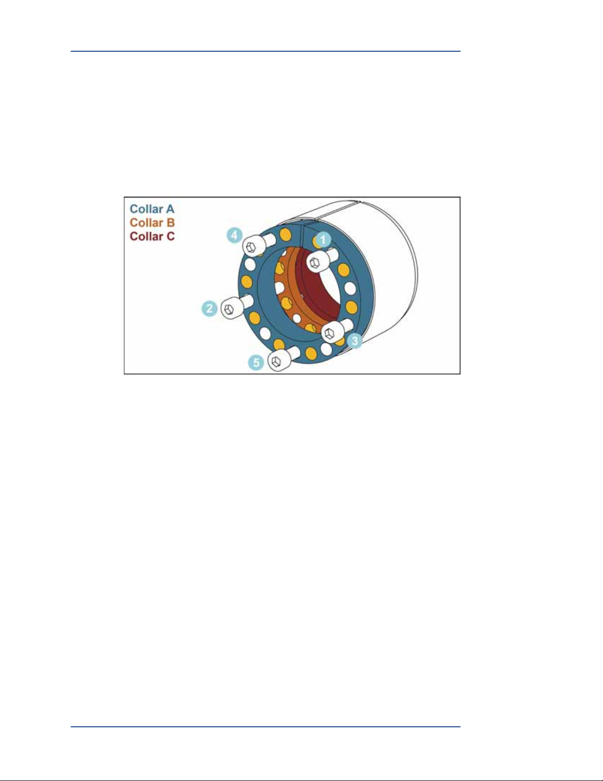
5. Finish tightening the five screws by using the following guidelines.
• Tighten screws 30 degrees at a time in the pattern shown in Figure 6 until you
reach 30 ft-lbs of torque with each screw.
• Do not exceed 30 ft-lbs of torque with any screw.
• Do not tighten past the minimum distance indicated in Figure 7. Tightening
past this minimum distance may damage the locking device.
While tightening the screws, the torque should suddenly lighten twice. This
indicates that both taper rings are unlocked. If the torque does not lighten, repeat
step 5, but turn each screw less than 30 degrees at a time.
Figure 6: Tsubaki Unlocking Hole Location and Unlocking Pattern
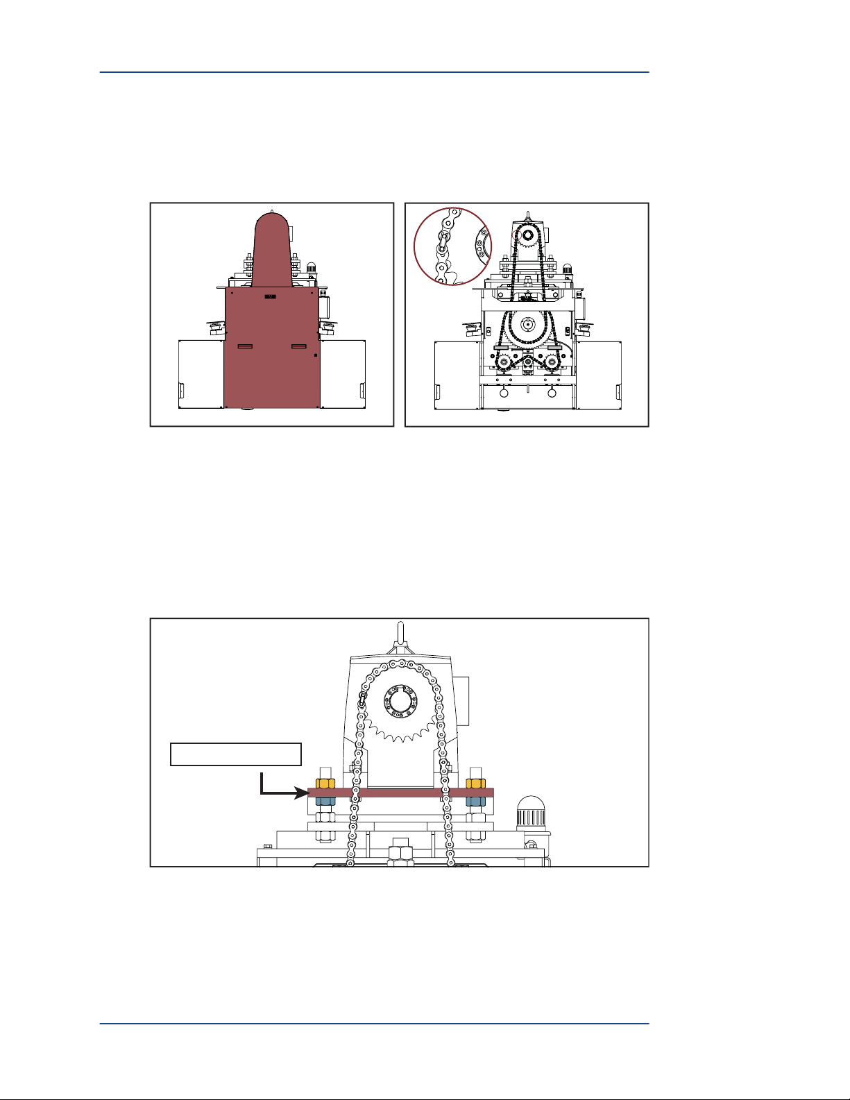
Figure 7: Tsubaki Screw Tightening Distance
6. Once the taper rings have unlocked, remove the locking device and drive sprocket
from the drive shaft.
7. Proceed based on whether you are replacing or reinstalling a locking device.
• If you are replacing a locking device, retain the screws as spares and discard
the locking device. Skip to page 11.
• If you are reinstalling the existing locking device, retain the screws and
locking device. Skip to page 11.
Minimum Distance = 0.47"
Cross Section