JZ990D43401E
How to obtain manuals
How to obtain manuals
For product manuals or documents, consult with the Mitsubishi Electric dealer
from who you purchased your product.
Registration
The company names and product names described in this manual are the
trademarks or registered trademarks of their respective companies.
Safety Precaution (Read these precautions before use.)
This manual classifies the safety precautions into two categories:
and .
Depending on the circumstances, procedures indicated by may
also cause severe injury.
It is important to follow all precautions for personal safety.
In case of trouble, in spite of our best efforts in quality control, it may be
assumed to cause continuous running state due to failure of the clutch and
the brake, and hence it is advised to pay sufficient consideration to safety
measures at the machine side.
Store this manual carefully so that it can be referred to when required, and
make sure to send it to the end user.
Indicates that incorrect handling may cause
hazardous conditions, resulting in death or severe
injury.
Indicates that incorrect handling may cause
hazardous conditions, resulting in medium or slight
personal injury or physical damage.
Use protective cover.
The rotating elements are exposed outside, and the
hand or part of body may be injured if touching the
product. Install a protective cover, allowing smooth
ventilation, so that part of the body may not be in
contact with the machine. It is also recommended to
provide with a safety mechanism to stop the rotating
elements immediately when the cover is opened.
Mitsubishi Electric is not responsible for any damage or trouble caused by
repair, disassembly or modification of the product by any third party other than
Mitsubishi or specified agent.
For repair or disassembly services, therefore, please call the service network of
Mitsubishi.
Warranty
Exclusion of loss in opportunity and secondary loss from warranty liability
Regardless of the gratis warranty term, Mitsubishi shall not be liable for
compensation to:
(1) Damages caused by any cause found not to be the responsibility of Mitsubishi.
(2) Loss in opportunity, lost profits incurred to the user by Failures of Mitsubishi
products.
(3) Special damages and secondary damages whether foreseeable or not,
compensation for accidents, and compensation for damages to products other
than Mitsubishi products.
(4) Replacement by the user, maintenance of on-site equipment, start-up test run
and other tasks.
For safe use
This product has been manufactured as a general-purpose part for general
industries, and has not been designed or manufactured to be incorporated in a
device or system used in purposes related to human life.
Before using the product for special purposes such as nuclear power, electric
power, aerospace, medicine or passenger movement vehicles, consult with
Mitsubishi Electric.
This product has been manufactured under strict quality control. However
when installing the product where major accidents or losses could occur if the
product fails, install appropriate backup or failsafe functions in the system.
1. Cautions before use
1) The powder is contained inside, and hence never give impact or incline the
product.
2) Don’t leave the product in a damp place.
3) Don’t pull or tear the lead wire, and handle with care.
Never use the unit in an atmosphere in which
inflammation or explosion is expected.
While slipping, a spark may be ignited on the internal
working surface. Never use in a flammable or explosive
atmosphere with oil or grease. Enclose the main body
when using near flammable material such as cotton.
When enclosed, however, it must be noted that the
allowable heat dissipation is lowered.
Keep the product away from water, oil, and grease.
Not only the working surface but also the product main
body should be protected from water, oil, and grease. If
water, oil, or grease is on the main body, it may flow to the
working surface and may remarkably lower the torque. As
a result, the machine may not stop at the specified point
due to inertial run, or may run at an abnormal speed.
Such abnormal operation of the machine may cause injury.
Check the environments.
Never use in a place exposed to dust, high temperature,
dew condensation, rain and wind, oil mist. Don't install
directly in a place exposed to vibration or impact. Or it
may lead to damage or malfunction of the product or
deterioration of performance.
This manual confers no industrial property rights or any rights of any other kind,
nor does it confer any patent licenses. Mitsubishi Electric Corporation cannot be
held responsible for any problems involving industrial property rights which may
occur as a result of using the contents noted in this manual.
Never suspend the product by holding the leadwire.
Or the lead wire may be broken and the product may drop
to cause injury.
Hold the product itself when attaching or detaching.
If the product is not used for a long time, store the clutch
at a non-humid place, or take measures to protect the
clutch from moisture.
If the inside of the product is moistened, the product may
be corroded and operation may not be possible, or the
performance may be deteriorated.
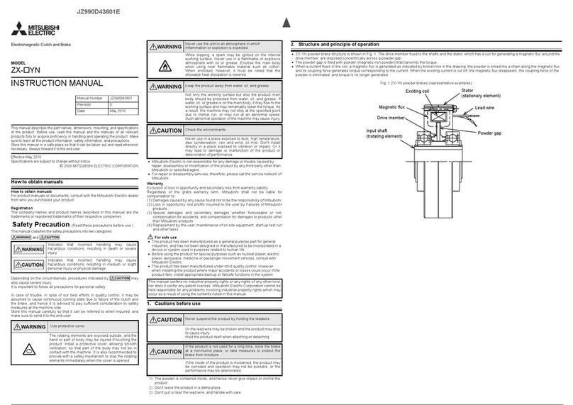
2. Structure and principle of operation
The clutch structure is shown in Fig. 1. The drive member linked to the input side and the driven member linked to the output side are disposed concentrically
across a powder gap.
The powder gap is filled with powder (magnetic iron powder), and the coil for passing a magnetic flux to the powder is built in the stator, and it is designed to feed
direct current from outside through the lead wire.
The brake has the driven member and exciting coil unit integrated into one body as shown in Fig.2.
While the drive member is rotating, when a current flows in the coil, a magnetic flux is generated as indicated by broken line in the drawing, and the powder is
linked like a chain along the magnetic flux, and its coupling force the driven member is driven, and the torque is transmitted to the output side.
When the exciting current is cut off, the magnetic flux disappears, and the coupling force of the powder is eliminated, thereby cutting of transmission of powder to
the driven member.
Fig. 1 Structural diagrams of ZA-A powder clutches (representative examples)
Fig. 2 Structural diagrams of ZA-Y powder brakes (representative examples)
Powder gap Magnetic flux
Bracket
Driven member (input)
Driven member
Ring drive
Stator
Fin
Coil
Driven member
shaft (output)
Exciting coil
(stationary element)
Magnetic flux
Driven member
(stationary element)
Powder gap
Drive member
(rotating element)
Bracket B (rotating element)
Bearing
Bracket C
(stationary element)
Input shaft
(rotating element)
3. Assembling of clutch, brake
(Note) The hoist operation by using the eyebolts should be done by a
qualified operator.
Turn off the power, and make sure rotating elements
are stopped.
Never work while rotating, or it may cause electric
shock or injury. When mounting, dismounting, or
adjusting, turn off the power source, and make sure
the rotating elements are stopped still. At this time,
be careful not to have fingers or hand pinched.
Tighten bolts to specified torque, and lock securely.
Depending on the degree of tightening, the bolts may
be broken to cause injury. Using specified bolt
material, tighten bolts to specified torque, and lock
securely with adhesive, spring washer or the like as
specified. Besides, since the parts composing the
product rotate relatively to each other, the tightened
parts must be fixed securely for the safety of
operation.
The bolt strength and tightening torque are
designated in the specification.
Connect lead wires securely.
Otherwise it may lead to an electric shock.
Connect securely, both electrically and mechanically,
and insulate appropriately.
Be sure to connect a surge absorber parallel to the
exciting coil to cut off the direct current.
Cutting off the current may cause a large surge
voltage, and the surge voltage may deteriorate the
peripheral units.
For this reason, be sure to use a surge absorber,
such as a diode, varistor, and protective resister.
Use wire size suited to current capacity.
If wire of smaller current capacity is used, the
insulating coating may melt down to cause insulation
failure, possibly leading to electric shock, current
leak, or fire.
The specified current of the product is designated in
the specification.
Mount, dismount, and transport with greatest care.
Carrying of a heavy product may cause lumbago or
injury by dropping.
Be careful sufficiently when mounting, dismounting,
or transporting.
In particular, handle the product provided with
eyebolts by using a hoist or the like.
1) Make sure there is enough clearance when installing the product to prevent
impact and undue force from being applied to the product during assembly
work. Especially, when inserting the output shaft into the shaft on the
machine side, make sure to support the shaft part of the driven member.
2) Use the powder clutch in the regular installation status in which the high-
speed rotation side is located as the input side. (The nameplate indicates
the input side and output side with arrows.)
Install both the clutch and brake so that the shafts become horizontal.
3) For coupling with the load shaft, use an elastic coupling.
4) For pulley coupling, pay attention to the belt tension, and never apply initial
tension more than necessary.
5) For the clutch, use the bolt hole on the fin side to prevent undue force
from being applied to the product and stop rotation of the stator.
If it is completely fixed, the bearing could be damaged.
6) The voltage polarity is not specified.
Fig. 3 Mounting of ZA-A powder clutches (For shaft drive)
Nut
Powder
clutch
Elastic
coupling
Motor Fin
Bearing
Output
shaft
Fin rotation
prevention
plate
Fin rotation
prevention
plate
Bolt
Space
Space
Enlargement
4. Operation
If a shock is applied to the clutch during transportation, powder may be
scattered inside the clutch. For this reason, before starting regular operation,
perform running-in while following the procedure below to collect powder into
the powder gap, if necessary.
1) Running-in procedure
Fix the output shaft to prevent rotation. (If it is difficult to fix the shaft, apply
a heavy load to prevent rotation of the output shaft.)
After that, without flowing the exciting current, rotate the drive member at
approximately 200 r/min for 1 minute, and then set the exciting current to 1/
4 to 1/2 of the rated value. While rotating the drive member, flow the
exciting current for 5 seconds, and then stop flowing the current for 10
seconds. Repeat this cycle approximately 10 times.
2) End of running-in
While the running-in is insufficient, the torque output may be low or the
torque may fluctuate, but as the running-in becomes sufficient and the
powder comes to work effectively, a stable torque corresponding to the
exciting current is produced.
After the running-in, start regular operation.
Depending on the conditions of use, the drive member surface temperature may
rise considerably. Use the product while keeping the surface temperature below
100°C. If the surface temperature exceeds 100°C, relax the operation conditions,
and prevent overheat of the clutch.
The above-described surface temperature is a reference value. Be sure to use the
clutch within the allowable heat dissipation.
(Herein, the surface temperature is mentioned on the basis of the ambient
temperature of 30°C. The allowable ambient temperature range is 0 to 40°C.)
Never touch the product during operation.
The rotating elements are exposed outside, and the hand
or part of body may be injured if touching the product.
Install a protective cover, allowing smooth ventilation, so
that the hand or fingers may not be in contact with the
machine during operation, and also a safety mechanism
to stop the rotating elements immediately when the cover
is opened.
Remove eye-bolts after assembly
(ZA-20A1, ZA-20Y1, ZA-40Y)
Eye-bolts are projecting, and may contact safety cover or
the like to cause breakage or injury. Remove right after
assembling, and then start operation.
Never increase the rotating speed more than allowable.
If the rotating speed is raised more than allowable,
vibration increases to cause breakage and scattering of
powder, and it is very dangerous. Rotate within allowable
speed, and install protective cover.
Use thermometer when measuring temperature.
Don't touch directly by hand to avoid burns. Turn off
the power source, and make sure the rotating
elements are stopped still, and measure with
thermometer.
Measure promptly.
5. Torque adjustment
The relation of torque and exciting current is almost proportional as shown
in Fig. 4, and therefore by adjusting the current, the torque can be easily
adjusted.
Set to a proper value in consideration of the finish of the product or
working condition.
Fig. 4 Exciting current vs. torque characteristics
(representative examples)
Use within rated torque.
If used over the rated torque, not only the
performance deteriorates, but also mechanical
breakage or injury may be caused. Hence, use with
rated torque. In particular, it must be noted that a
torque over the rating may be cause even if used at
the rated current, and therefore check the current-
torque characteristic, and adjust the exciting current.
(In the course of use, the torque gradually declines,
and therefore in manufacturing, a proper allowance
is considered initially.)
Use within the allowable heat dissipation.
If used over allowable heat dissipation, the clutch
may be extremely heated, and the working surface
may be extremely hot and red. As a result, a fire may
be caused. In addition, the performance may be
deteriorated. Be sure to use within the allowable heat
dissipation (refer to Fig. 5).
0
10
20
30
40
0.0 0.5 1.0 1.5
Exciting current (A)
Torque (N•m)
ZA-1.2A1
ZA-2.5A1
ZA-0.6A1
0
50
100
150
200
250
300
0.0 0.5 1.0 1.5 2.0 2.5
Exciting current (A)
Torque (N•m)
ZA-10A
1
ZA-20A
1
ZA-5A
1
MODEL
ZA-A1
ZA-Y1, ZA-Y
INSTRUCTION MANUAL
This manual describes the part names, dimensions, mounting, and specifications
of the product. Before use, read this manual and the manuals of all relevant
products fully to acquire proficiency in handling and operating the product. Make
sure to learn all the product information, safety information, and precautions.
Store this manual in a safe place so that it can be taken out and read whenever
necessary. Always forward it to the end user.
Effective May 2018
Specifications are subject to change without notice.
2006 MITSUBISHI ELECTRIC CORPORATION
Manual Number JZ990D43401
Revision E
Date May 2018

