- 4 -
CONTENTS
– FILE “COVERPGE” –
NOTES FOR SERVICING RoHS-COMPLIANT PRODUCTS ............................................................................... 2
SPECIFICATIONS................................................................................................................................................. 3
CONTENTS........................................................................................................................................................... 4
– FILE “DIAGNO” –
DIAGNOSIS INFORMATION................................................................................................................................. 1
STATUS LED indicator..................................................................................................................................... 1
SPECIFICATION OF INPUT SIGNALS IN EACH INPUT OF THE PROJECTOR ................................................ 2
– FILE “EXPOSED” –
TRADE MARK, REGISTERED TRADEMARK...................................................................................................... 1
PRODUCT SAFETY NOTICE ............................................................................................................................... 1
SAFETY PRECAUTIONS...................................................................................................................................... 2
PRECAUTIONS FOR RESOLDERING................................................................................................................. 3
PCB LOCATION .................................................................................................................................................... 4
EXPOSED VIEW................................................................................................................................................... 6
Chassis ASSY 1............................................................................................................................................... 6
Chassis ASSY 2............................................................................................................................................... 8
Chassis ASSY 3............................................................................................................................................... 10
DISASSEMBLY ..................................................................................................................................................... 12
1. Removal of the Top cover ASSY.................................................................................................................. 12
2. Removal of the KEY SWITCH PCB ASSY................................................................................................... 12
3. Removal of the IR PCB ASSY (FRONT)...................................................................................................... 12
4. Removal of the LAMP COVER PCB ASSY ................................................................................................. 12
5. Removal of the TEMP SENSOR PCB ASSY (POWER).............................................................................. 13
6. Removal of the LAMP POWER PCB ASSY................................................................................................. 13
7. Removal of the TEMP SENSOR PCB ASSY (OUTLET) ............................................................................. 14
8. Removal of the Fan (Inlet) / Fan (Outlet) ..................................................................................................... 14
9. Removal of the Power fan ........................................................................................................................... 15
10. Removal of the POWER PCB ASSY ......................................................................................................... 15
11. Removal of the Duct fan (Inlet) .................................................................................................................. 16
12. Removal of the LFT PCB ASSY................................................................................................................. 17
13. Removal of the MEMC PCB ASSY............................................................................................................ 17
14. Removal of the SCALER PCB PCB ASSY / HDMI PCB ASSY ................................................................. 17
15. Removal of the Lamp unit / Optical unit / Cooling fan (optical).................................................................. 18
16. Removal of the IR PCB ASSY (REAR)...................................................................................................... 19
17. Removal of the Thermostat ....................................................................................................................... 19
18. Removal of the I/O PCB ASSY / TEMP SENSOR PCB ASSY (INLET)..................................................... 20
19. Removal of the AC inlet ............................................................................................................................. 20
LEAD DRESS........................................................................................................................................................ 21
LABEL POSITION ................................................................................................................................................. 49
PACKING............................................................................................................................................................... 50
– FILE “MAINTENA” –
REPLACING THE LAMP....................................................................................................................................... 1
MAINTENANCE .................................................................................................................................................... 4
DOWNLOAD OF THE FIRMWARE....................................................................................................................... 5
LIFE TIME OF THE CONSUMABLE PARTS ........................................................................................................ 8
– FILE “PCCONTRL” –
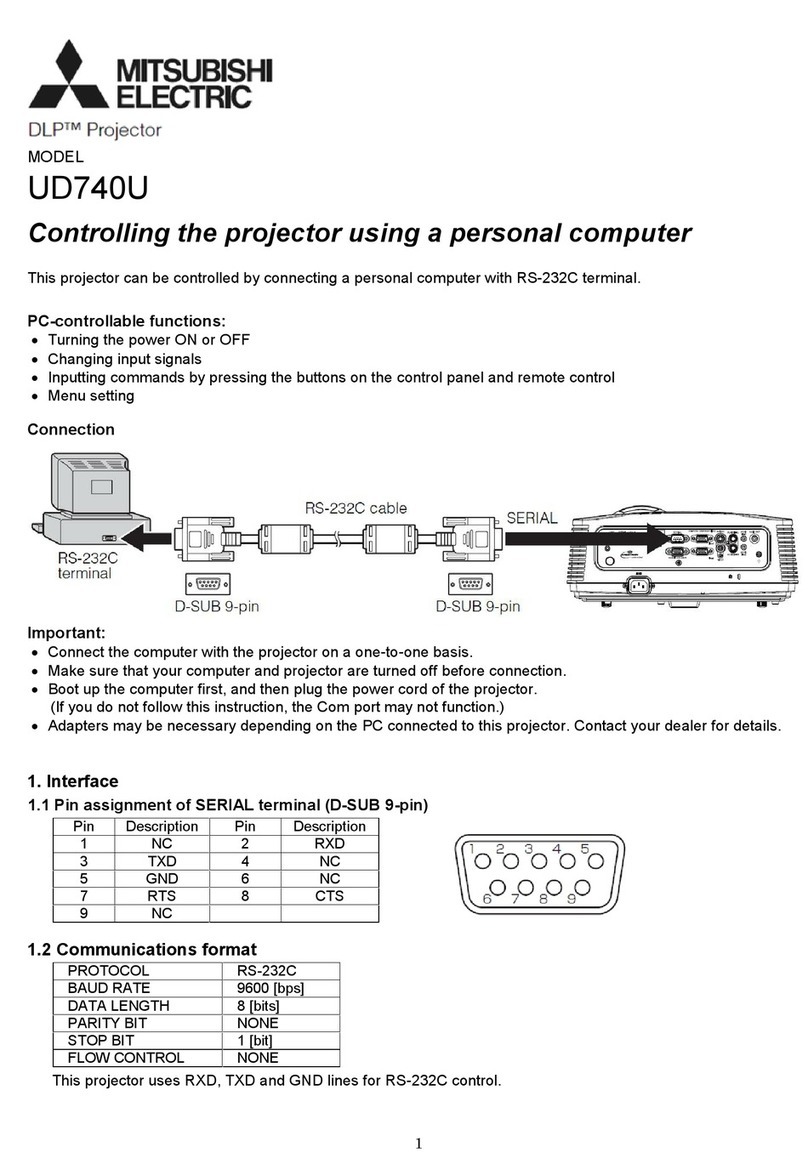
Controlling the projector using a personal computer............................................................................................. 1
– FILE “PARTSLST” –
PARTS LIST .......................................................................................................................................................... 1
PCB LOCATION .............................................................................................................................................. 2
EXPOSED VIEW ............................................................................................................................................. 3
Chassis ASSY 1 ......................................................................................................................................... 3
Chassis ASSY 2 ......................................................................................................................................... 4
Chassis ASSY 3 ......................................................................................................................................... 5
PACKING AND ACCESSORY ......................................................................................................................... 6
PACKING ................................................................................................................................................... 6
ACCESSORY............................................................................................................................................. 6
ELECTRICAL PARTS AND OTHERS.............................................................................................................. 7
– FILE “SHEMATC” –
BLOCK DIAGRAM........................................................................................................................................... B-1
SCHEMATIC DIAGRAMS................................................................................................................................ C-1


