Specications are subject to change without notice. © 2021 Mitsubishi Electric US, Inc.
MANUFACTURED FOR:
MITSUBISHI ELECTRIC US, INC.
PAC-USSEN001-FM-1
1. Safety Instructions
INSTALLATION/INSTRUCTION MANUAL
For your safety, rst be sure to read 1.Safety Instructions and then
install the Flush Mount Room Temperature Sensor
PAC-USSEN001-FM-1 correctly.
FOR INSTALLER
Flush Mount Room Temperature Sensor
1. Safety Precautions
This sensor is not polarity sensitive and includes 24” of 22/2 AWG (ETFE) stranded etched Teflon wires for
making all of the proper connections. Mitsubishi Electric recommends using 22/2 AWG UL 1007 non-
shielded wire for up to 100’ with this application. Temperature measurement range: 41° to +140˚ F (5° to
+60˚ C)
• The following two symbols are used to denote dangers that may be caused by incorrect use and their
degree:
This symbol denotes what could lead to serious injury or death if your misuse the PAC-USSEN001-FM-1.
This symbol denotes what could lead to a personal injury or damage to your property if you misuse the PAC-USSEN001-FM-1.
• After reading this installation manual, keep it in a place where the final user can see it anytime he or she
wants to.
When someone moves, repairs or uses the PAC-USSEN001-FM-1, make sure that this manual is
forwarded to the final user.
Ask your dealer or technical representative to
install the unit.
Any deficiency caused by your installation may
result in an electric shock or fire.
Ensure that installation work is done
correctly following this installation manual.
Any deficiency caused by installation may result
in an electric shock or fire.
Install In a place which is strong enough to
withstand the weight of the PAC-USSEN001-
FM-1.
Any lack of strength may cause the PAC-
USSEN001-FM-1 to fall down, resulting in
personal injury.
All electrical work roost be performed by a
licensed technician, according to local
regulations and the Instructions given In this
manual.
Any lack of electric circuit or any deficiency
caused by installation may result in an electric
shock or fire.
Firmly connect the wiring using the specified
cables. Carefully check that the cables do not
exert any force on the terminals.
Improper wiring connections may produce heat
and possibly a fire.
Do not move and re-Install the PAC-
USSEN001-FM-1 yourself.
Any deficiency caused by installation may result
in an electric shock or fire.
Ask your distributor or special vendor for moving
and installation.
Never modify or repair the PAC-USSEN001-
FM-1 by yourself.
Any deficiency caused by your modification or
repair may result in an electric shock or fire.
Consult with your dealer about repairs.
Do not turn on the main power until
installation has been completed.
Fail to do so may cause an electric shock or fire.
5 © 2018 Mitsubishi Electric US, Inc.
6DIHW\3UHFDXWLRQV
7KLVVHQVRULVQRWSRODULW\VHQVLWLYHDQGLQFOXGHV´RI$:*(7)(VWUDQGHGHWFKHG7HIORQZLUHVIRU
PDNLQJDOORIWKHSURSHUFRQQHFWLRQV0LWVXELVKL(OHFWULFUHFRPPHQGVXVLQJ$:*8/QRQ
VKLHOGHGZLUHIRUXSWR¶ZLWKWKLVDSSOLFDWLRQ7HPSHUDWXUHPHDVXUHPHQWUDQJHWRÛ)WR
Û&
7KHIROORZLQJWZRV\PEROVDUHXVHGWRGHQRWHGDQJHUVWKDWPD\EHFDXVHGE\LQFRUUHFWXVHDQGWKHLU
GHJUHH
:$51,1
7KLVV\PEROGHQRWHVZKDWFRXOGOHDGWRVHULRXVLQMXU\RUGHDWKLI\RXUPLVXVHWKH3$&866(1)0
&$87,21
7KLVV\PEROGHQRWHVZKDWFRXOGOHDGWRDSHUVRQDOLQMXU\RUGDPDJHWR\RXUSURSHUW\LI\RXPLVXVHWKH3$&866(1)0
$IWHUUHDGLQJWKLVLQVWDOODWLRQPDQXDONHHSLWLQDSODFHZKHUHWKHILQDOXVHUFDQVHHLWDQ\WLPHKHRUVKH
ZDQWVWR
:KHQVRPHRQHPRYHVUHSDLUVRUXVHVWKH3$&866(1)0PDNHVXUHWKDWWKLVPDQXDOLV
IRUZDUGHGWRWKHILQDOXVHU
:$51,1
$VN\RXUGHDOHURUWHFKQLFDOUHSUHVHQWDWLYHWR
LQVWDOOWKHXQLW
$Q\GHILFLHQF\FDXVHGE\\RXULQVWDOODWLRQPD\
UHVXOWLQDQHOHFWULFVKRFNRUILUH
(QVXUHWKDWLQVWDOODWLRQZRUNLVGRQH
FRUUHFWO\IROORZLQJWKLVLQVWDOODWLRQPDQXDO
$Q\GHILFLHQF\FDXVHGE\LQVWDOODWLRQPD\UHVXOW
LQDQHOHFWULFVKRFNRUILUH
,QVWDOO,QDSODFHZKLFKLVVWURQJHQRXJKWR
ZLWKVWDQGWKHZHLJKWRIWKH3$&866(1
)0
$Q\ODFNRIVWUHQJWKPD\FDXVHWKH3$&
866(1)0WRIDOOGRZQUHVXOWLQJLQ
SHUVRQDOLQMXU\
$OOHOHFWULFDOZRUNmustEHSHUIRUPHGE\D
OLFHQVHGWHFKQLFLDQDFFRUGLQJWRORFDO
UHJXODWLRQVDQGWKHiQVWUXFWLRQVJLYHQiQWKLV
PDQXDO
$Q\ODFNRIHOHFWULFFLUFXLWRUDQ\GHILFLHQF\
FDXVHGE\LQVWDOODWLRQPD\UHVXOWLQDQHOHFWULF
VKRFNRUILUH
)LUPO\FRQQHFWWKHZLULQJXVLQJWKHVSHFLILHG
FDEOHV&DUHIXOO\FKHFNWKDWWKHFDEOHVGRQRW
H[HUWDQ\IRUFHRQWKHWHUPLQDOV
,PSURSHUZLULQJFRQQHFWLRQVPD\SURGXFHKHDW
DQGSRVVLEO\DILUH
'RQRWPRYHDQGUHiQVWDOOWKH3$&
866(1)0\RXUVHOI
$Q\GHILFLHQF\FDXVHGE\LQVWDOODWLRQPD\UHVXOW
LQDQHOHFWULFVKRFNRUILUH
$VN\RXUGLVWULEXWRURUVSHFLDOYHQGRUIRUPRYLQJ
DQGLQVWDOODWLRQ
1HYHUPRGLI\RUUHSDLUWKH3$&866(1
)0E\\RXUVHOI
$Q\GHILFLHQF\FDXVHGE\\RXUPRGLILFDWLRQRU
UHSDLUPD\UHVXOWLQDQHOHFWULFVKRFNRUILUH
&RQVXOWZLWK\RXUGHDOHUDERXWUHSDLUV
'RQRWWXUQRQWKHPDLQSRZHUXQWLO
LQVWDOODWLRQKDVEHHQFRPSOHWHG
)DLOWRGRVRPD\FDXVHDQHOHFWULFVKRFNRUILUH
0LWVXELVKL(OHFWULF86,QF
&$87,21
'RQRWLQVWDOOLQDQ\SODFHH[SRVHGWR
IODPPDEOHJDVOHDNDJH
)ODPPDEOHJDVHVDFFXPXODWHGDURXQGWKHERG\
RI3$&866(1)0PD\FDXVHDQ
H[SORVLRQ
'RQRWLQVWDOOLQDQ\SODFHZKHUHDQDFLGLFRU
DONDOLQHVROXWLRQRUVSHFLDOVSUD\DUHRIWHQ
XVHG
'RLQJVRPD\FDXVHDQHOHFWULFVKRFNRU
PDOIXQFWLRQ
'RQRWXVHLQDQ\VSHFLDOHQYLURQPHQW
8VLQJLQDQ\SODFHH[SRVHGWRRLOLQFOXGLQJ
PDFKLQHRLOVWHDPDQGVXOIXULFJDVPD\
GHWHULRUDWHWKHSHUIRUPDQFHVLJQLILFDQWO\RUJLYH
GDPDJHWRWKHFRPSRQHQWSDUWV
8VHVWDQGDUGZLUHVLQFRPSOLDQFHZLWKWKH
FXUUHQWFDSDFLW\
$IDLOXUHWRdo
WKLVPD\UHVXOWLQDQHOHFWULF
OHDNDJH, KHDWLQJRUILUH
:LUHVRWKDWiWGRHVQRWUHFHLYHDQ\WHQVLRQ
7HQVLRQPD\FDXVHZLUHEUHDNDJHKHDWLQJRU
ILUH
'RQRWLQVWDOOLQDQ\a place with much
steamVXFKDs EDWKURRPRUNLWFKHQ
$YRLGDQ\SODFHZKHUHPRLVWXUHLVFRQGHQVHG
iQWRGHZ
'RLQJVRPD\FDXVHDQHOHFWULFVKRFNRUD
PDOIXQFWLRQ
&RPSOHWHO\VHDOWKHZLUHOHDGLQSRUWZLWK
SXWW\HWF
$Q\GHZPRLVWXUHFRFNURDFKHVRULQVHFWV
HQWHULQJWKHXQLWPD\FDXVHDQHOHFWULFVKRFNRU
PDOIXQFWLRQ
'RQRWWRXFKDQ\3&%3ULQWHG&LUFXLW%RDUG
ZLWK\RXUKDQGVRUZLWKWRROV'RQRWDOORZ
GXVWWRFROOHFWRQWKH3&%
'RLQJVRPD\FDXVHDILUHRUDQHOHFWULFVKRFN
'RQRWZDVKZLWKZDWHU
'RLQJVRPD\FDXVHDQHOHFWULFVKRFNRUD
PDOIXQFWLRQ
'RQRWLQVWDOO,QDQ\SODFHDWDWHPSHUDWXUHRI
PRUHWKDQ &RUOHVVWKDQ &RUH[SRVHG
WRGLUHFWVXQOLJKW
3$&866(1)0
6SHFLILFDWLRQVDUHVXEMHFWWRFKDQJHZLWKRXWQRWLFH
2. Conrming the Supplied Parts
2. Confirming the Supplied Parts
Confirm that following parts are enclosed in the box in addition to this Installation Manual
• Flush Mount Sensor
• Threaded Insert
• Noise Filter Board with CN20 Connector
• Conversion cable
• Instruction Sheet
PAC-USSEN001-FM-1
7 © 2018 Mitsubishi Electric US, Inc.
3. Mounting Instructions
3. Mounting Instructions
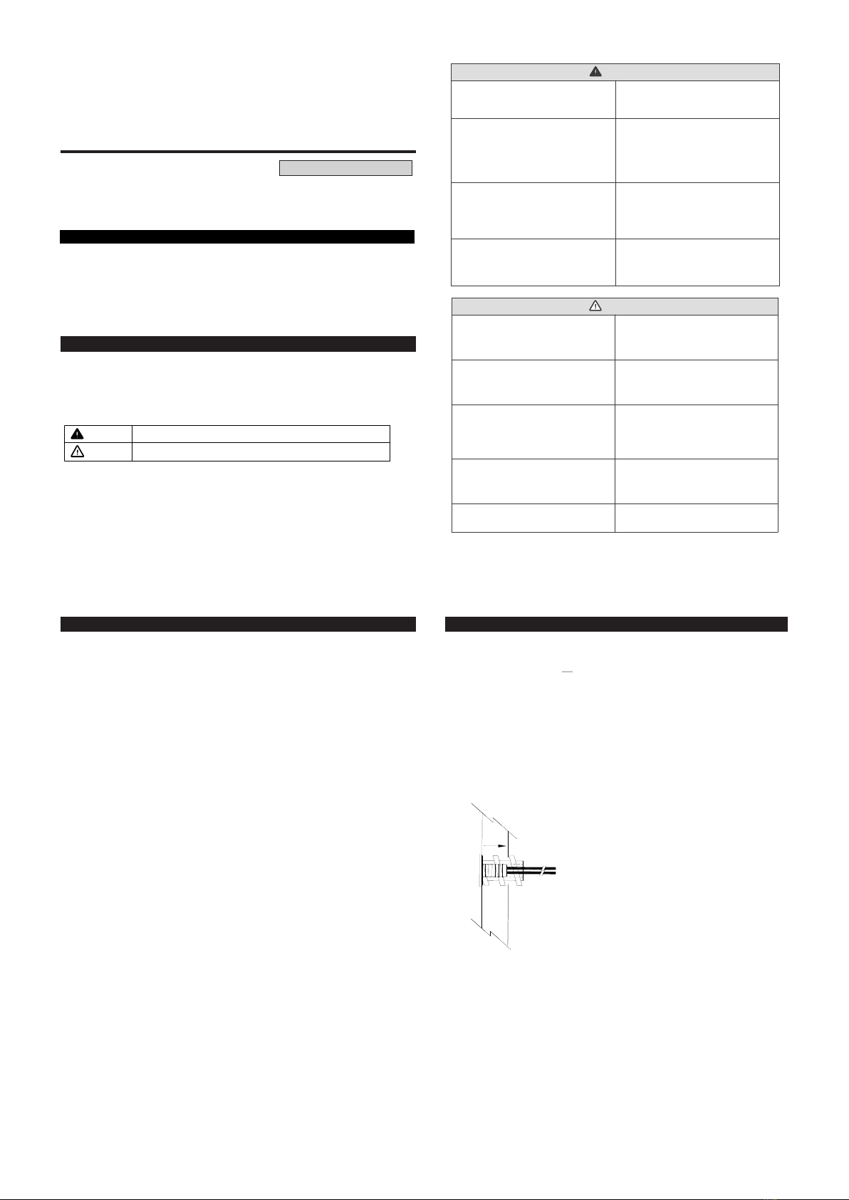
1. Select location for installation
• Select a place where the sensor will detect
an average temperature of the room.
• Make sure that the sensor is not in direct
sunlight, miscellaneous heat sources, drafts,
outside wall or supply air from the unit itself.
These may generate incorrect readings.
• Drill, or cut open a hole into the wall where
the sensor will be installed. For hollow walls,
the hole should be ½”.
• Mount the sensor with the threaded insert
inside of this hole by turning it clockwise
until it sits flush with the wall.
• When mounting into solid walls (i.e. marble
or rock) a ¼” hole is recommended, and the
threaded corkscrew insert is not required.
• Field wire must be provided on site.
Figure 1
2. Connect the wires
• Connect the Sensor wires to the field wires
using crimp connectors or wire nuts.
• Connect the loose end of the field wires to
the wires extending from the noise filter
board.
• Connect CN20 connector from the noise
filter board to CN20 on the indoor unit
control board.
• For indoor units without a CN20 connector,
use the conversion cable included. Connect
the CN20 connector from the noise filter
board to the female end of the conversion
cable. Connect the J01 connector to the
indoor unit board.
PAC-USSEN001-FM-1
Specifications are subject to change without notice. 8
Contents
1. Safety Instructions
2. Conrming the Supplied Parts
3. Mounting Instructions
4. Troubleshooting
5. Setting Indoor Units
6. Thermistor Calibration Table


