Specications are subject to change without notice. © 2022 Mitsubishi Electric US, Inc.
MANUFACTURED FOR:
MITSUBISHI ELECTRIC US, INC.
PAC-USSEN002-FM-1
INSTALLATION/INSTRUCTION MANUAL
For your safety, rst be sure to read 1.Safety Instructions and then
install the Flush Mount Room Temperature Sensor
PAC-USSEN002-FM-1 correctly.
FOR INSTALLER
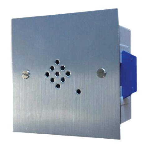
Flush Mount Room Temperature Sensor
Contents
1. Safety Instructions
2. Conrming the Supplied Parts
3. Mounting Instructions
4. Troubleshooting
5. Setting Indoor Units
6. Thermistor Calibration Table
1. Safety Instructions
This sensor is not polarity sensitive and includes 24” of 22/2 AWG (ETFE) stranded
etched Teon wires for making all of the proper connections. Mitsubishi Electric US,
Inc. recommends using 22/2 AWG UL 1007 non-shielded wire for up to 100’ with this
application. Temperature measurement range: 41° to +140˚ F (5° to +60˚ C)
Warning This symbol denotes what could lead to serious injury or death if
your misuse the PAC-USSEN002-FM-1.
Caution
This symbol denotes what could lead to a personal
injury or damage to your property if you misuse the
PAC-USSEN002-FM-1.
After reading this installation manual, keep it in a place where the nal user can see
it anytime he or she wants to.
When someone moves, repairs or uses the PAC-USSEN002-FM-1, make sure that
this manual is forwarded to the nal user.
WARNING
Ask your dealer or technical
representative to install the unit.
Any deciency caused by your installation
may result in an electric shock or re.
Ensure that installation work
is done correctly following this
installation manual.
Any deciency caused by
installation may result in an electric
shock or re.
Install in a place which is strong
enough to withstand the weight of the
PAC-USSEN002-FM-1.
Any lack of strength may cause the
PAC-USSEN002-FM-1 to fall down,
resulting in personal injury.
All electrical work must be
performed by a licensed
technician, according to local
regulations and the instructions
given in this manual.
Any lack of electric circuit or any
deciency caused by installation
may result in an electric shock
or re.
Firmly connect the wiring using the
specied cables. Carefully check that
the cables do not exert any force on
the terminals.
Improper wiring connections may produce
heat and possibly a re.
Do not move and re-install the
PAC-USSEN002-FM-1 yourself.
Any deciency caused by
installation may result in an electric
shock or re.
Ask your dealer for moving and
installation.
Never modify or repair the
PAC-USSEN002-FM 1 by yourself.
Any deciency caused by your
modication or repair may result in an
electric shock or re. Consult with your
dealer about repairs.
Do not turn on the main power
until installation has been
completed.
Failure to do so may cause an
electric shock or re.
CAUTION
Do not install in any place exposed to
ammable gas leakage.
Flammable gases accumulated around the
body of PAC-USSEN002-FM-1 may cause
an explosion.
Do not install in any place where an
acidic or alkaline solution or special
spray are often used.
Doing so may cause an electric shock
or malfunction.
Do not use in any special environment.
Using in any place exposed to oil (including
machine oil), steam and sulfuric gas may
deteriorate the performance signicantly or
give damage to the component parts.
Use standard wires in compliance
with the current capacity.
A failure to do this may result in an
electric leakage, heating or re.
Wire so that it does not receive any
tension.
Tension may cause wire breakage, heating
or re.
Do not install in a place with much
steam such as bathroom or kitchen.
Avoid any place where moisture is
condensed into dew.
Doing so may cause an electric shock
or a malfunction.
Completely seal the wire lead-in port
with putty, etc.
Any dew, moisture, cockroaches or insects
entering the unit may cause an electric
shock or malfunction.
Do not touch any PCB (printed
circuit board) with your hands or
with tools. Do not allow dust to
collect on the PCB.
Doing so may cause a re or an
electric shock.
Do not wash with water.
Doing so may cause an electric shock or a
malfunction.
Do not install in any place at a
temperature of more than 40° C or
less than 0° C or exposed to direct
sunlight.
2. Conrming the Supplied Parts
3. Mounting Instructions
1. Select location for installation.
• Select a place where the sensor will detect an average temperature of the
room.
• Make sure that the sensor is not in direct sunlight, miscellaneous heat
sources, drafts, outside wall or supply air from the unit itself. These may
generate incorrect readings.
• Drill or cut open a hole into the wall where the sensor will be installed. For
hollow walls, the hole should be ½”.
• Mount the sensor with the threaded insert inside of this hole by turning it
clockwise until it sits ush with the wall.
• When mounting into solid walls (i.e. marble or rock) a ¼” hole is
recommended, and the threaded corkscrew insert is not required.
• Field wire must be provided on site.
2. Connect the wires.
• Connect the sensor wires to the eld wires using crimp connectors or wire
nuts.
• Connect the loose end of the eld wires to the wires extending from the noise
lter board.
• Connect CN20 connector from the noise lter board to CN20 on the indoor
unit control board.
Conrm that following parts are enclosed
in the box in addition to this installation
manual.
• Flush mount sensor
• Threaded insert
• Noise lter board with CN20
connector
• Instruction sheet
ATTENTION
PAC-USSEN002-FM-1 does not
come with the conversion cable
and is not compatible with the
following indoor units: PEFY-NMHU,
PFFY-NEMU and PFFY-NRMU.


