Mitsubishi Electric PUH-P8MYA Operating manual

TECHNICAL & SERVICE MANUAL
HEAT PUMP PUH-P8MYA, PUH-P10MYA
(Single and Twin/Triple/Four)
Models
AIR-COOLED SPLIT-TYPE
PACKAGED AIR CONDITIONERS
<Outdoor unit>
2003
For use with the R407C

Page
Contents
1 PRECAUTIONS FOR DEVICES THAT USE R407C REFRIGERANT ...................................... 1
[1] Storage of Piping Material ...................................................................................................2
[2] Piping Machining ................................................................................................................. 3
[3] Necessary Apparatus and Materials and Notes on Their Handling ..................................... 4
[4] Brazing................................................................................................................................. 5
[5] Airtightness Test .................................................................................................................. 6
[6] Vacuuming ........................................................................................................................... 6
[7] Charging of Refrigerant ....................................................................................................... 7
2 SPECIFICATIONS ...................................................................................................................... 8
3 EXTERNAL DIMENSIONS ....................................................................................................... 10
4 ELECTRICAL WIRING DIAGRAM ............................................................................................ 11
[1] Outdoor Unit ....................................................................................................................... 11
[2] Skelton of Indoor/Outdoor Connection .............................................................................. 12
5 Technical Data of PUH-8/10YD to Meet LVD ......................................................................... 13
[1] Standard Operation Data ................................................................................................... 13
[2] Cooling Capacity Curves ................................................................................................... 14
[3] Heating Capacity Curves ................................................................................................... 14
[4] Capacity Reduction Ratio due to Changes in Piping Length ............................................. 15
[5] Center of Gravity (Outdoor unit) ........................................................................................ 16
[6] NC Curve (Outdoor unit) ................................................................................................... 17
6 SERVICE DATA ........................................................................................................................ 18
[1] Appearance of Equipment ................................................................................................. 18
[2] Refrigerant Circuit .............................................................................................................. 20
[3] Limitation of Refrigerant Piping Length.............................................................................. 20
[4] Refrigerant Piping .............................................................................................................. 21
[5] Refrigerant Charge ............................................................................................................ 21
[6] Operation Rage ................................................................................................................. 21
7 CONTROL ................................................................................................................................ 22
[1] Composition of Control ...................................................................................................... 22
[2] Control specifications......................................................................................................... 23
[3] Function of switches and connectors (outdoor unit) .......................................................... 27
[4] Simple parts check method ............................................................................................... 35
[5] Reference Data.................................................................................................................. 36
[6] Troubleshooting of each part ............................................................................................. 37
[7] Emergency operation......................................................................................................... 40
[8] Self-diagnosis and troubleshooting.................................................................................... 42
8 Test run .................................................................................................................................... 51

–1–
1 PRECAUTIONS FOR DEVICES THAT USE R407C REFRIGERANT
Caution
Do not use the existing refrigerant piping.
• The old refrigerant and refrigerator oil in the existing
piping contains a large amount of chlorine which may
cause the refrigerator oil of the new unit to deterio-
rate.
Use refrigerant piping made of C1220 (CU-DHP) phos-
phorus deoxidized copper as specified in the *JIS
H3300 “Copper and copper alloy seamless pipes and
tubes”. In addition, be sure that the inner and outer
surfaces of the pipes are clean and free of hazard-
ous sulphur, oxides, dust/dirt, shaving particles, oils,
moisture, or any other contaminant.
• Contaminants on the inside of the refrigerant piping
may cause the refrigerant residual oil to deteriorate.
*JIS: Japanese Industrial Standard
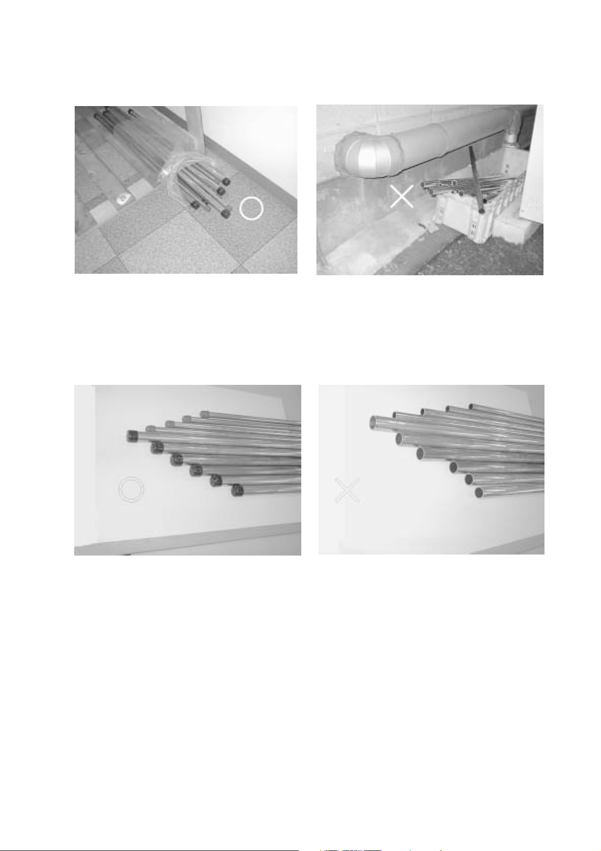
Store the piping to be used during installation indoors
and keep both ends of the piping sealed until just
before brazing. (Store elbows and other joints in a
plastic bag.)
• If dust, dirt, or water enters the refrigerant cycle, de-
terioration of the oil and compressor trouble may re-
sult.
Use ester oil, ether oil or alkylbenzene (small amount)
as the refrigerator oil to coat flares and flange con-
nections.
• The refrigerator oil will degrade if it is mixed with a
large amount of mineral oil.
Use liquid refrigerant to seal the system.
• If gas refrigerant is used to seal the system, the com-
position of the refrigerant in the cylinder will change
and performance may drop.
Do not use a refrigerant other than R407C.
• If another refrigerant (R22, etc.) is used, the chlorine
in the refrigerant may cause the refrigerator oil to de-
teriorate.
Use a vacuum pump with a reverse flow check valve.
• The vacuum pump oil may flow back into the refriger-
ant cycle and cause the refrigerator oil to deteriorate.
Do not use the following tools that have been used
with conventional refrigerants.
(Gauge manifold, charge hose, gas leak detector, re-
verse flow check valve, refrigerant charge base,
vacuum gauge, refrigerant recovery equipment)
• If the conventional refrigerant and refrigerator oil are
mixed in the R407C, the refrigerant may deteriorated.
• If water is mixed in the R407C, the refrigerator oil may
deteriorate.
• Since R407C does not contain any chlorine, gas leak
detectors for conventional refrigerants will not react to
it.
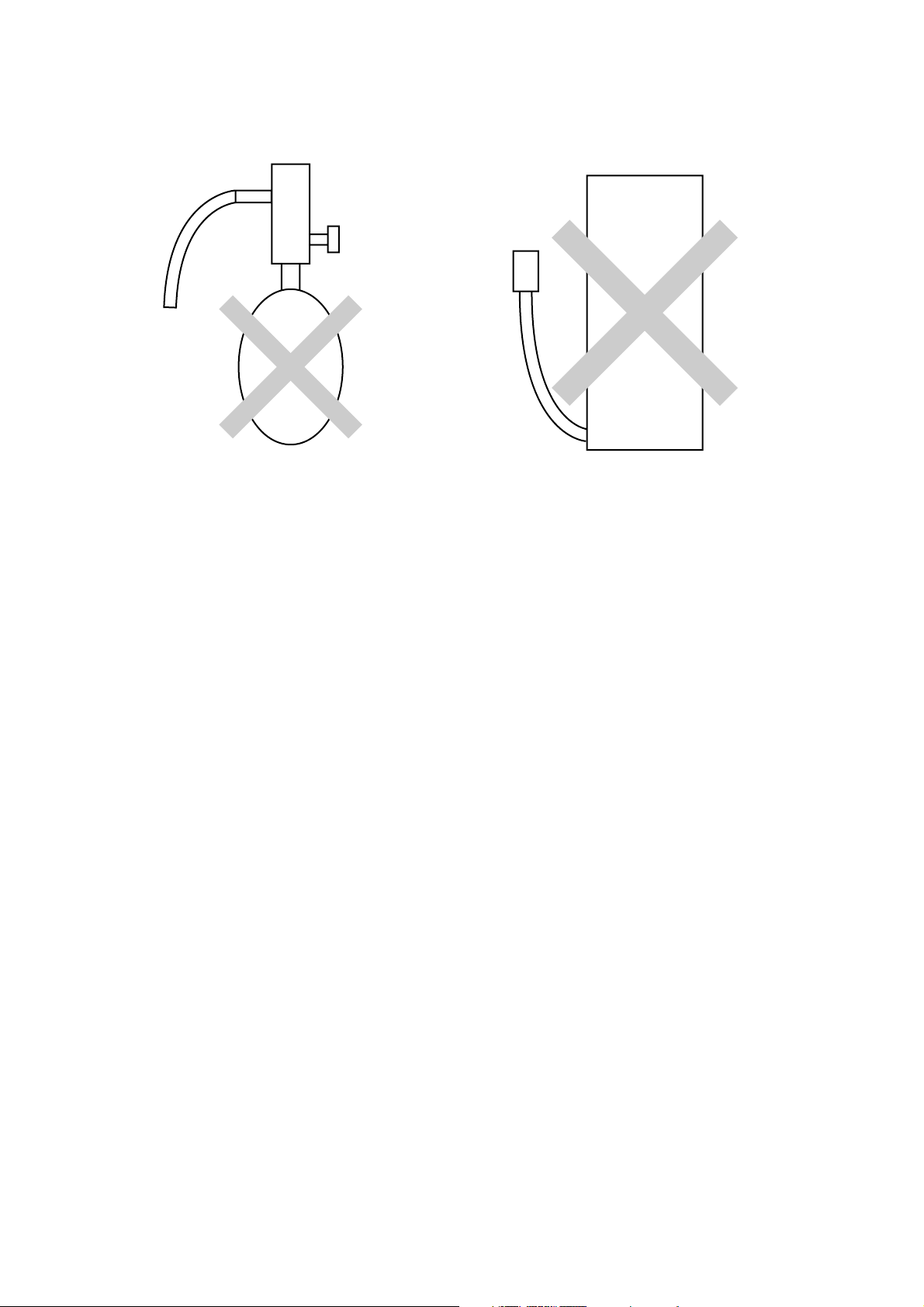
Do not use a charging cylinder.
• Using a charging cylinder may cause the refrigerant
to deteriorate.
Be especially careful when managing the tools.
• If dust, dirt, or water gets in the refrigerant cycle, the
refrigerant may deteriorate.
If the refrigerant leaks, recover the refrigerant in the
refrigerant cycle, then recharge the cycle with the
specified amount of the liquid refrigerant indicated
on the air conditioner.
• Since R407C is a nonazeotropic refrigerant, if addi-
tionally charged when the refrigerant leaked, the com-
position of the refrigerant in the refrigerant cycle will
change and result in a drop in performance or abnor-
mal stopping.

–2–
[1] Storage of Piping Material
(1) Storage location
Store the pipes to be used indoors. (Warehouse at site or owner’s warehouse)
Storing them outdoors may cause dirt, waste, or water to infiltrate.
(2) Pipe sealing before storage
Both ends of the pipes should be sealed until immediately before brazing.
Wrap elbows and T’s in plastic bags for storage.
* The new refrigerator oil is 10 times more hygroscopic than the conventional refrigerator oil (such as Suniso). Water
infiltration in the refrigerant circuit may deteriorate the oil or cause a compressor failure. Piping materials must be stored
with more care than with the conventional refrigerant pipes.

–3–
[2] Piping Machining
Use ester oil, ether oil or alkylbenzene (small amount) as the refrigerator oil to coat flares and flange connections.
Use only the necessary minimum quantity of oil !
Reason:
1. The refrigerator oil used for the equipment is highly hygroscopic and may introduce water inside.
Notes:
• Introducing a great quantity of mineral oil into the refrigerant circuit may also cause a compressor failure.
• Do not use oils other than ester oil, ether oil or alkylbenzene.

–4–
[3] Necessary Apparatus and Materials and Notes on Their Handling
The following tools should be marked as dedicated tools for R407C.
<<Comparison of apparatus and materials used for R407C and for R22>>
Apparatus Used Use R22 R407C
Gauge manifold Evacuating, refrigerant filling Current product
Charging hose Operation check Current product
Charging cylinder Refrigerant charging Current product Do not use
Gas leakage detector Gas leakage check Current product Shared with R134a
Refrigerant collector Refrigerant collection R22 For R407C use only
Refrigerant cylinder Refrigerant filling R22 Identification of dedi-
cated use for R407C:
Record refrigerant name
and put brown belt on
upper part of cylinder.
Vacuum pump Vacuum drying Current product Can be used by attach-
ing an adapter with a
check valve.
Vacuum pump with a check valve Current product
Flare tool Flaring of pipes Current product
Bender Bending of pipes Current product
Application oil Applied to flared parts Current product Ester oil or Ether oil or
Alkybenzene (Small
amount)
Torque wrench Tightening of flare nuts Current product
Pipe cutter Cutting of pipes Current product
Welder and nitrogen cylinder Welding of pipes Current product
Refrigerant charging meter Refrigerant charging Current product
Vacuum gauge Checking the vacuum degree Current product
Symbols: To be used for R407C only. Can also be used for conventional refrigerants.
Tools for R407C must be handled with more care than those for conventional refrigerants. They must not come into contact
with any water or dirt.

–5–
[4] Brazing
No changes from the conventional method, but special care is required so that foreign matter (ie. oxide scale, water, dirt,
etc.) does not enter the refrigerant circuit.
Example: Inner state of brazed section
When non-oxide brazing was not used When non-oxide brazing was used
Items to be strictly observed:
1. Do not conduct refrigerant piping work outdoors on a rainy day.
2. Apply non-oxide brazing.
3. Use a brazing material (Bcup-3) which requires no flux when brazing between copper pipes or between a copper
pipe and copper coupling.
4. If installed refrigerant pipes are not immediately connected to the equipment, then braze and seal both ends of them.
Reasons:
1. The new refrigerant oil is 10 times more hygroscopic than the conventional oil. The probability of a machine failure if
water infiltrates is higher than with conventional refrigerant oil.
2. A flux generally contains chlorine. A residual flux in the refrigerant circuit may generate sludge.
Note:
• Commercially available antioxidants may have adverse effects on the equipment due to its residue, etc. When
applying non-oxide brazing, use nitrogen.

–6–
[5] Airtightness Test
No changes from the conventional method. Note that a refrigerant leakage detector for R22 cannot detect R407C leakage.
Halide torch R22 leakage detector
Items to be strictly observed:
1. Pressurize the equipment with nitrogen up to the design pressure and then judge the equipment’s airtightness, taking
temperature variations into account.
2. When investigating leakage locations using a refrigerant, be sure to use R407C.
3. Ensure that R407C is in a liquid state when charging.
Reasons:
1. Use of oxygen as the pressurized gas may cause an explosion.
2. Charging with R407C gas will lead the composition of the remaining refrigerant in the cylinder to change and this
refrigerant can then not be used.
Note:
• A leakage detector for R407C is sold commercially and it should be purchased.
[6] Vacuuming
1. Vacuum pump with check valve
A vacuum pump with a check valve is required to prevent the vacuum pump oil from flowing back into the refrigerant
circuit when the vacuum pump power is turned off (power failure).
It is also possible to attach a check valve to the actual vacuum pump afterwards.
2. Standard degree of vacuum for the vacuum pump
Use a pump which reaches 0.5 Torr (500 MICRON) or below after 5 minutes of operation.
In addition, be sure to use a vacuum pump that has been properly maintained and oiled using the specified oil. If the
vacuum pump is not properly maintained, the degree of vacuum may be too low.
3. Required accuracy of the vacuum gauge
Use a vacuum gauge that can measure up to 5 Torr. Do not use a general gauge manifold since it cannot measure a
vacuum of 5 Torr.
4. Evacuating time
• Evacuate the equipment for 1 hour after –755 mmHg (5 Torr) has been reached.
• After envacuating, leave the equipment for 1 hour and make sure the that vacuum is not lost.
5. Operating procedure when the vacuum pump is stopped
In order to prevent a backflow of the vacuum pump oil, open the relief valve on the vacuum pump side or loosen the
charge hose to drawn in air before stopping operation.
The same operating procedure should be used when using a vacuum pump with a check valve.

–7–
[7] Charging of Refrigerant
R407C must be in a liquid state when charging, because it is a non-azeotropic refrigerant.
For a cylinder with a syphon attached For a cylinder without a syphon attached
Cylinder color identification R407C-Gray Charged with liquid refrigerant
R410A-Pink
Reasons:
1. R407C is a mixture of 3 refrigerants, each with a different evaporation temperature. Therefore, if the equipment is
charged with R407C gas, then the refrigerant whose evaporation temperature is closest to the outside temperature is
charged first while the rest of refrigerants remain in the cylinder.
Note:
• In the case of a cylinder with a syphon, liquid R407C is charged without turning the cylinder up side down. Check the
type of cylinder before charging.
Cylin-
der
Cylin-
der
Valve Valve
Liquid Liquid

–8–
Cooling Heating
18,000 20,400
20.9 23.7
3N~ 380/400/415 V 50 Hz
7.27 7.17
13.0 12.8
Propeller fan ×1
185
0.38
Hermetic
5.5
0.05 (240 V)
R407C/FVC68D
Steel plate painting with polyester powder
(MUNSELL 5Y8/1 or similar)
1,715(H) ×990(W) ×840(L)
3.3
Overcurrent protection/Thermal switch
ø12.7 Flare /
ø25.4 Flange
PEH-P8MYA
56
215
Indoor: 15 °CWB~24 °CWB Indoor: 15°CDB~27 °CDB
Outdoor: –5 °CDB~46 °CDB
Outdoor: –12 °CWB~18 °CWB
2 SPECIFICATIONS
Specifications of air-source heat pump type packaged air conditioner
(Outdoor unit)
Model name PUH-P8MYA Quantity
Capacity kcal/h
kW
Power source
Power input kW
Current A
Type x Quantity
Fan Airflow rate m3/min
Motor output kW
Type
Compressor Motor output kW
Crankcase heater kW
Refrigerant/Lubricant
External finish
External dimension mm
High pressure protection MPa
Compressor/Fan
Refrigerant piping diameter Liquid/Gas mm
Indoor unit
Noise level dB (A)
Net weight kg
Operating temperature range
Notes:
1. Cooling/Heating capacity indicates the maximum value at operation under the following condition.
Cooling Indoor: 27 °CDB/19 °CWB Outdoor: 35
°
CDB
Heating Indoor: 20 °CDB Outdoor: 7
°
CDB/6 °CWB
Pipe length: 7.5 m Height difference: 0 m
2. Works not included: Installation/Foundation work, Electrical connection work, Duct work, Insulation
work, Power source switch, and other items not specified in this specifications.
Protection
device

–9–
Cooling Heating
22,400 26,200
26.0 30.5
3N~ 380/400/415 V 50 Hz
9.02 8.62
16.0 15.4
Propeller fan ×1
185
0.38
Hermetic
7.5
0.05 (240 V)
R407C/FVC68D
Steel plate painting with polyester powder
(MUNSEL 5Y8/1 or similar)
1,715(H) ×990(W) ×840(L)
3.3
Overcurrent protection/Thermal switch
ø12.7 Flare / ø28.6 Flange
PEH-P10MYA
57
220
Indoor: 15 °CWB~24 °CWB Indoor: 15 °CDB~27 °CDB
Outdoor: –5 °CDB~46 °CDB Outdoor: –12 °CWB~18 °CWB
Specifications of air-source heat pump type packaged air conditioner
(Outdoor unit)
Model name PUH-P10MYA Quantity
Capacity kcal/h
kW
Power source
Power input kW
Current A
Type x Quantity
Fan Airflow rate m3/min
Motor output kW
Type
Compressor Motor output kW
Crankcase heater kW
Refrigerant/Lubricant
External finish
External dimension mm
High pressure protection MPa
Compressor/Fan
Refrigerant piping diameter Liquid/Gas mm
Indoor unit
Noise level dB (A)
Net weight kg
Operating temperature range
Notes:
1. Cooling/Heating capacity indicates the maximum value at operation under the following condition.
Cooling Indoor: 27 °CDB/19 °CWB Outdoor: 35 °CDB
Heating Indoor: 20 °CDB Outdoor: 7 °CDB/6 °CWB
Pipe length: 7.5 m Height difference: 0 m
2. Works not included: Installation/Foundation work, Electrical connection work, Duct work, Insulation
work, Power source switch, and other items not specified in this specifications.
Protection
device

–10–
3 EXTERNAL DIMENSIONS
• Models PUH-P8MYA/P10MYA
65
60
84
100 251
234
60 75
194
100
48
80 40
121
50
65
840
910
15
880
15
990
215 215
560
1715
225
1490
413
55
190
149
40
70
165
31
80
79
55
378
160
25
198
237
80
73
Service panel
4-14X20 holes
<For mounting
anchor bolt M8>
(Field supply)
Plane view
Rear view Left side view
Front view
Right side view
Refrig. service
valve (liquid)
φ
12.7<flare>
Refrig. service
valve(gas)
<flange>
φ
38.1 Knockout hole
<Bottom side hole for
the power supply>
φ
38.1 Knockout hole
<Left side hole for
the power supply>
Knockout hole
<Front side hole for
the power supply and
control wiring>
φ
38.1 Knockout hole
<Right side hole for
the power supply>
φ
25.4 Knockout hole
<Bottom side hole for
the control wiring>
φ
25.4 Knockout hole
<Left side hole for
the control wiring>
φ
25.4 Knockout hole
<Right side hole for
the control wiring>
Knockout hole
Left piping hole
Knockout hole
Front piping hole
Knockout hole
Pressure gauge
(for option)
Knockout hole
Rear piping hole
(It is necessary
for the option)
Connecting pipe
8 :
φ
25.4<brazed>
10 :
φ
28.6<brazed>
Note 1
Note 2
Note 3
Knockout hole
Bottom piping hole
Cross section X-X Cross section Y-Y
XX
Y
Y
Air outlet
Air
inlet
Air
inlet
<Accessory>
• Refrigerant connecting pipe ...................................... 1pc.
(The connecting pipe is fixed with the unit)
• Packing for connecting pipe ...................................... 1pc.
(It is attached control box cover)
• Conduit mounting plate
(Painted the same color as the unit body)
φ
27 ............................................................................ 1pc.
φ
34 ............................................................................ 1pc.
φ
40 ............................................................................ 1pc.
• Tapping screw 4 x 12 .............................................. 4pcs.
Note: 1. Please leave a space under the outdoor unit for
the piping when you connected the piping from
the bottom.
(Please be careful not to close the hole of the
bottom plate by the basement.)
2. It is possible to change to
φ
27 or
φ
34 by selecting
the conduit mounting plate.
3. The hole size can be selected to
φ
27 or
φ
34 or
φ
40 by selecting the conduit mounting plate.

–11–
POWER SUPPLY
50HZ
380/400/415V
3N~PE
(3P)
C12
(3P)
C11
PUH-P8MYA-EU : 50A
PUH-P10MYA-EU: 60A
(FIELD SUPPLY)
CIRCUIT BREAKER
(2P)
C14
RED
WHITE WHITE
52C
X1
RED
GREEN/YELLOW
6
3
X1
3
BLACK
BLUE
1
21S4
CN51
(5P)
F01
F10
F20
F1
F30
TH1
1
51C
1
CN52
CN25
CN26
3
3
5
63L
3
1
CN21
63H1
3
1
CN22
3
1
CN23
MC
52C
CH
X03
X01
X04
BLACK
SV1
5
X02
X05
CNFC1
1
6
F04
F02
Transmission
Circuit
DC power
supply
CN34
L1
31
CN3D
CNVMNT
CN3S
1
CN24
CN27
3
63H2
CN3N
51C
52C
L1
CN40 CN4CN3
21
CN2
CNMNT
CNOUT1
CNOUT2
CN53
3
1
MF
1
6
LEV
1
3
5
7
5
11
33
135
TR
(7P)
CN20
(6P)
(6P)
(3P)
(3P)
(5P)
(3P)
(3P)
(3P)
(5P)
CNIN
(7P)
(3P)
(3P)
CNFG
(3P)
CNS3 CN28
(3P) (3P)
(3P)
(3P)
(3P)
(3P)
(3P)
(3P) (5P) (2P)
(6P) (2P) (2P)
CNFC2
(6P)
CNFAN
(5P)
F.C.
BOARD
CNPO
(5P)
TH2 TH3
SW2
1
O
OFF
6
16
SW1
O
OFF
SW5
2
1
O
OFF
SW3
4
O
OFF
1
SW4
LED1
F03
L2 L3 N PE
PE
F2 PE
7
1
N
L2
L3
313131
2121
13 1
2
1
(3P)
CN81
3
1
OUT OUT ININ
N.F.BOARD
S1 S2 S3
TO INDOOR UNIT
CONNECTING WIRES (*2)
(POLER)
INDOOR UNIT
S3
S2
S1
TB4
OUTDOOR UNIT CONTROL BOX
(*1)
(*3)
TB1
TB3 TB8
4 ELECTRICAL WIRING DIAGRAM
[1] Outdoor Unit
• Model PUH-P8MYA/P10MYA
Symbol Name
F1, F2 FUSE (15A 250VAC CLASS T)
F01~F04 FUSE (6.3A 250VAC CLASS F)
F10~F30 FUSE (6.3A 250VAC CLASS F)
51C OVER CURRENT RELAY (COMPRESSOR)
52C MAGNETIC CONTACTOR (COMPRESSOR)
63L PRESSURE SWITCH (LOW PRESSURE)
63H1 PRESSURE SWITCH (HIGH PRESSURE)
63H2 PRESSURE SWITCH (FOR CONTROL)
MC COMPRESSOR MOTOR
MF FAN MOTOR (OUTDOOR)
TR TRANSFORMER
X1 AUXILIARY RELAY (FOR 16, 20HP)
LED 1 LED (FOR SERVICE)
XO1~X05 AUXILIARY RELAY (MAIN BOARD)
CN2,CN20~28
CN3,34,30,3N,3S
CN4,40,51~53,81
CONNECTOR MAIN BOARD
CNFC1, FG, S3
CNMT,VMNT
Symbol Name
SW1~SW5 SWITCH (MAIN BORD)
21S4 4-WAY VALVE
SV1 SOLENOID VALVE
CH CRANK CASE HEATER (COMPRESSOR)
LEV ELECTRINIC EXPANSION VALVE
TH1 LIQUID TEMP.
TH2 THERMISTOR DISCHARGE TEMP.
TH3 COND./EVA. TEMP.
TB1 POWER SOURCE TERMINAL BLOCK
TB3, 4 OUTDOOR/INDOOR CONNECTION TERMINAL BLOCK
TB8 TERMINAL BLOCK (FOR 16, 20HP)
C11, C12 CONNECTOR (FAN MOTOR)
C14 CONNECTOR (63H2)
CAFAN, CNFC2
CONNECTOR (F. C. BOARD)
CNPO
CNOUT1, 2
CONNECTOR (N, F. BOARD)
CNIN
Note :
1. Be sure to apply earth work to the unit.
(Use the earth terminal of TB1.)
2. The dotted lines show field wiring.
3. Color of earth wire is yellow and green
twisting.
4. This motor (*1) includes auto reset type
internal thermostat.
5. Indoor and outdoor connecting wires
(*2) are made with polarities, make
sure matching wiring and terminal.
6. SW5 (*3) is shown PUH-P10MYA set-
ting.
In case of PUH-P8MYA setting is
shown as below.
Caution :
1. To protect compressor from abnormal cur-
rent, over current relays is installed. There-
fore, do not change factory set value of over
current relays.
(*3)
14
SW5
ON
OFF

–12–
Indoor Units
PEH-P*MYA
PLH-P*KAH, PLH-P*AAH
PLA-P*KA, PLA-P*AA
PEHD-P*EAH, PEAD-P*EA
PCH-P*GAH, PCA-P*GA
PKH-P*GALH, PKH-P*FALH
PKA-P*GAL, PKA-P*FAL
PSH-P*GAH, PSA-P*GA
Indoor Units
PEH-P*MYA
PLH-P*KAH, PLH-P*AAH
PLA-P*KA, PLA-P*AA
PEHD-P*EAH, PEAD-P*EA
PCH-P*GAH, PCA-P*GA
PKH-P*GALH, PKH-P*FALH
PKA-P*GAL, PKA-P*FAL
PSH-P*GAH, PSA-P*GA
Multi distributor pipes
(Option)
25 : 25 : 25 : 25
2HP+2HP
+2HP+2HP
–
–
2.5HP+2.5HP+
2.5HP+2.5HP
–
–
SDT-1111SA-E
[2] Skelton of Indoor/Outdoor Connection
(1) Applicable combinations of 8 & 10HP [PUH-P8MYA/P10MYA]
(2) System
Indoor units
Distributor
Remote
controller
Outdoor unit Pipe work
Transmission
line
3-core cable
Distributor
Remote
controller
Outdoor unit Pipe work
Transmission
line
3-core cable
Indoor unit
Remote
controller
Outdoor unit Pipe work
Transmission line
3-core cable
Indoor units
Twin
TripleSingle
Single
8HP
–
–
–
–
–
10HP
–
–
–
–
–
–
50 : 50
4HP+4HP
–
5HP+5HP
–
–
SDD-50WSA-E
33 : 33 : 33
2.5HP+2.5HP
+2.5HP
–
–
3HP+3HP
+3HP
–
SDT-111SA-E
25 : 25 : 50
2HP+2HP
+4HP
–
–
2.5HP+2.5HP
+5HP
–
–
–
SDT-112SA-E
20 : 40 : 40
1.6HP+3HP
+3HP
–
–
–
2HP+4HP
+4HP
–
–
SDT-122SA-E
PUH-P10MYA PUH-P8MYA
Four
Distributor
Remote
controller
Outdoor unit Pipe work
Transmission
line
3-core cable
Indoor units
* indicates applicable HP.

–13–
380 400 415 380 400 415
50 50 50 50 50 50
27/19 27/19 27/19 20/– 20/– 20/–
35/- 35/– 35/– 7/6 7/6 7/6
7.5 7.5 7.5 7.5 7.5 7.5
6.9 6.9 6.9 6.9 6.9 6.9
13.0 13.0 13.0 12.8 12.8 12.8
7.27 7.27 7.27 7.17 7.17 7.17
11.9 11.9 11.9 11.7 11.7 11.7
1.1 1.1 1.1 1.1 1.1 1.1
1.12 1.12 1.12 1.12 1.12 1.12
0.65 0.65 0.65 0.65 0.65 0.65
2.11 2.11 2.11 1.91 1.91 1.91
0.48 0.48 0.48 0.40 0.40 0.40
75 75 75 70 70 70
6 660 00
46 46 46 0 0 0
35 35 35 30 30 30
5 Technical Data of PUH-P8MYA/P10MYA to Meet LVD
[1] Standard Operation Data
(1) PUH-P8MYA
Operating condition
Operating condition Cooling Heating
Voltage V
Power source frequency Hz
Indoor air condition (DB/WB) °C
Outdoor air condition (DB/WB) °C
Piping length m
Refrigerant charge kg
Current A
Input kW
Compressor current A
Fan current A
Current A
Input kW
Discharge pressure MPa
Suction pressure MPa
Discharge refrigerant temperature °C
Suction refrigerant temperature °C
Liquid pipe temperature
(at piping sensor)
°C
Compressor shell bottom temperature °C
Outdoor unit
Indoor unit
Refrigerant circuit Electrical characteristics
380 400 415 380 400 415
50 50 50 50 50 50
27/19 27/19 27/19 20/– 20/– 20/–
35/- 35/– 35/– 7/6 7/6 7/6
7.5 7.5 7.5 7.5 7.5 7.5
7.4 7.4 7.4 7.4 7.4 7.4
16.0 16.0 16.0 15.4 15.4 15.4
9.02 9.02 9.02 8.62 8.62 8.62
14.9 14.9 14.9 14.3 14.3 14.3
1.1 1.1 1.1 1.1 1.1 1.1
1.64 1.64 1.64 1.64 1.64 1.64
0.94 0.94 0.94 0.94 0.94 0.94
2.22 2.22 2.22 1.75 1.75 1.75
0.50 0.50 0.50 0.38 0.38 0.38
80 80 80 65 65 65
888–1–1–1
48 48 48 0 0 0
30 30 30 20 20 20
(2) PUH-P10MYA
Operating condition
Operating condition Cooling Heating
Voltage V
Power source frequency Hz
Indoor air condition (DB/WB) °C
Outdoor air condition (DB/WB) °C
Piping length m
Refrigerant charge kg
Current A
Input kW
Compressor current A
Fan current A
Current A
Input kW
Discharge pressure MPa
Suction pressure MPa
Discharge refrigerant temperature °C
Suction refrigerant temperature °C
Liquid pipe temperature
(at piping sensor)
°C
Compressor shell bottom temperature °C
Outdoor unit
Indoor unit
Refrigerant circuit Electrical characteristics
Note: The values listed above indicate that when connected with the indoor unit PEH-P8MYA as representative data.
Note: The values listed above indicate that when connected with the indoor unit PEH-P10MYA as representative data.

–14–
[2] Cooling Capacity Curves
• PUH-P8MYA/P10MYA
[3] Heating Capacity Curves
• PUH-P8MYA/P10MYA
-5-3-113579111315171921232527293133353739414345
22
20
18
16
0.6
0.8
1
1.2
1.4
Capacity ratio
-5-3-113579111315171921232527293133353739414345
22
20
18
16
0.7
0.9
1.1
1.22
Input ratio
-12-10-8-6-4-2024681012141618
15
20
25
0.6
0.8
1
1.2
1.4
Capacity ratio
-12 -10 -8 -6 -4 -2 0 2 4 6 8 10 12 14 16 18
25
20
15
0.6
0.8
1
1.2
1.4
Input ratio
Indoor inlet air wet
bulb temp. <˚CWB>
inlet air wet
bulb temp. <˚CWB>
Indoor
Indoor inlet air dry
bulb temp. <˚CDB>
Indoor inlet air dry
bulb temp. <˚CDB>
Outdoor air temperature <˚CWB> Outdoor air temperature <˚CWB>
Outdoor air temperature <˚CDB> Outdoor air temperature <˚CDB>

–15–
[4] Capacity Reduction Ratio due to Changes in Piping Length
(1) Cooling capacity
(2) Heating capacity
(3) Calculation formula of equivalent piping length
PUH-P8MYA
PUH-P10MYA
Model name Equivalent piping length
- 30 m 30 - 50 m 50 - 70 m
1.0 0.995 0.99
PUH-P8MYA Equivalent piping length (m) = Actual piping length (m) + (0.47 ×Number of bend)
PUH-P10MYA Equivalent piping length (m) = Actual piping length (m) + (0.5 ×Number of bend)
6 1.0
4 0.98
2 0.88
0 0.85
–2 0.86
–4 0.89
–6 0.92
–8 0.92
–10 0.92
(4) Reduction ratio by frosting
Outdoor unit inlet wet bulb temperature Heating capacity reduction ratio
(°CWB)
Capacity ratio
Equivalent piping length (m)
0 10 20 30 40 50 60 70
0.8
0.9
1
PUH-P8MYA
Capacity ratio
Equivalent piping length (m)
0 10 20 30 40 50 60 70
0.8
0.9
1
PUH-P10MYA

–21–
[4] Refrigerant Piping
[5] Refrigerant Charge
Model Gas pipe Liquid pipe
PUH-P8MYA ø25.4 ø
12.7
PUH-P10MYA ø
28.58 ø
12.7
1.6, 2, 2.5, 3 ø
15.88 ø9.52
4, 5 ø19.05 ø
9.52
8ø
25.4 ø
12.7
10 ø28.58 ø
12.7
Outdoor unit
Indoor unit
[6] Operation Rage
-5 46
Outdoor air temperature (°CDB)
24
15
Indoor air temperature (°CWB)
–12 18
Outdoor air temperature (°CWB)
27
15
Indoor air temperature (°CDB)
Additional refrigerant charge
0.026×L + 0.014 ×( a+ b+ c+ d) + 1.7
×amount of indoor units. (kg)
0.026 ×L + 0.014 ×( a+ b+ c+ d) + 1.7
×amount of indoor units. (kg)
Amount of infusion of
coolant at ex-factory
R407C 6.0 kg
R407C 6.5 kg
L: Main section actual length a+ b+ c+ d: Join section actual length
The value of calculation result at the second decimal place must be rounded up to the first decimal place.
(e.g. 2.22 kg must be rounded up to 2.3 kg)
Model
PUH-P8MYA
PUH-P10MYA
Cooling Heating

–16–
[5] Center of Gravity (Outdoor unit)
PUH-P8MYA
PUH-P10MYA
XYZ
330 350 490 215
300 330 510 220
Item
Model name
Center of gravity (mm) Net weight
(kg)
(1) Caution for Lifting
Blow 40ß
Suspending spot
Protection pad
Name plate
Indicates the unit
front side.
Hanger rope (Over 7m ×2)
Service panel
XY
Z
Compressor position
Center of gravity
G
Inclining to the right
front side of unit.
2-point,front and rear
Warning
Must be durable against unit weight.
For the lifting of unit for movement, please
be sure to suspend at four points, and not
to give any shock to unit.
Never apply two-point lifting as it is
dangerous.
Use pads properly to
prevent the scratching of
external panel
caused by contact
with sling.
Fasten here properly
to prevent unit from
slipping off from
the sling at lifting.
Lift unit slowly by suspending rope uniformly
so that the rope will not slip off or unit will not
incline seriously.
Be careful that unit may fall down if the rope is
not in a proper position as the center or
gravity of unit is being inclined.
Below 40˚

–17–
OCTAVE BAND PRESSURE LEVEL< dB> 0dB = 0.0002 bar OCTAVE BAND PRESSURE LEVEL< dB> 0dB = 0.0002 bar
56 dB (A)
57 dB (A)
Sound pressure level in anechoic room
Measurement condition
63Hz
63
125Hz
60
250Hz
56
500Hz
56
1000Hz
51
2000Hz
47
4000Hz
44
8000Hz
40
(dB)
63Hz
63
125Hz
59
250Hz
56
500Hz
55
1000Hz
50
2000Hz
45
4000Hz
42
8000Hz
39
(dB)
1m
1m
A
B
1m
1m
A
B
NC60
NC50
NC40
NC30
NC20
Approximate minimum
audible limit on
continuous noise
70
60
50
40
30
20
63 125 250 500 1000 2000 4000 8000
10
OCTAVE BAND CENTER FREQUENCIES <Hz>
NC60
NC50
NC40
NC30
NC20
70
60
50
40
30
20
63 125 250 500 1000 2000 4000 8000
10
OCTAVE BAND CENTER FREQUENCIES <Hz>
Approximate minimum
audible limit on
continuous noise
[6] NC Curve (Outdoor unit)
(1) Octave Band Analysis
1) PUH-P8MYA
2) PUH-P10MYA
Note: The measuring point is 1m from the bottom of the unit (1m from the front of the unit).
This manual suits for next models
1
Table of contents
Other Mitsubishi Electric Split Type Air Conditioner manuals

Mitsubishi Electric
Mitsubishi Electric MSZ-FH25VE - E1 User manual

Mitsubishi Electric
Mitsubishi Electric MSZ-GB50VA Series User manual

Mitsubishi Electric
Mitsubishi Electric MSZ-FD25VA User manual

Mitsubishi Electric
Mitsubishi Electric PUZ-ZM100VKA User manual

Mitsubishi Electric
Mitsubishi Electric PEFY-P-VMHS-E User manual