Toshiba RAS-167SKV User manual

Indoor unit
RAS-167SKV Series
Outdoor unit
RAS-167SAV Series
AIR CONDITIONER (SPLIT TYPE)
INSTALLATION MANUAL
1110251217
ENGLISH
ESPAÑOL
FRANÇAIS
ITALIANO
DEUTSCH
PORTUGUÊS
POLSKI
ČESKY
HRVATSKI
MAGYAR
NEDERLANDS
ΕΛΛΗΝΙΚΑ
SVENSKA
SUOMI
NORSK
DANSK
ROMÂNĂ
БЪЛГАРСКИ
EESTI
LATVISKI
SLOVENČINA
SLOVENŠČINA
Cover 1110251217.indd 1Cover 1110251217.indd 11/13/10 4:49:26 PM1/13/10 4:49:26 PM

CONTENTS
PRECAUTIONS FOR SAFETY....................................................1
INSTALLATION DIAGRAM OF INDOOR AND
OUTDOOR UNITS .......................................................................2
nOptional Installation Parts .......................................................2
INDOOR UNIT..............................................................................3
nInstallation Place .....................................................................3
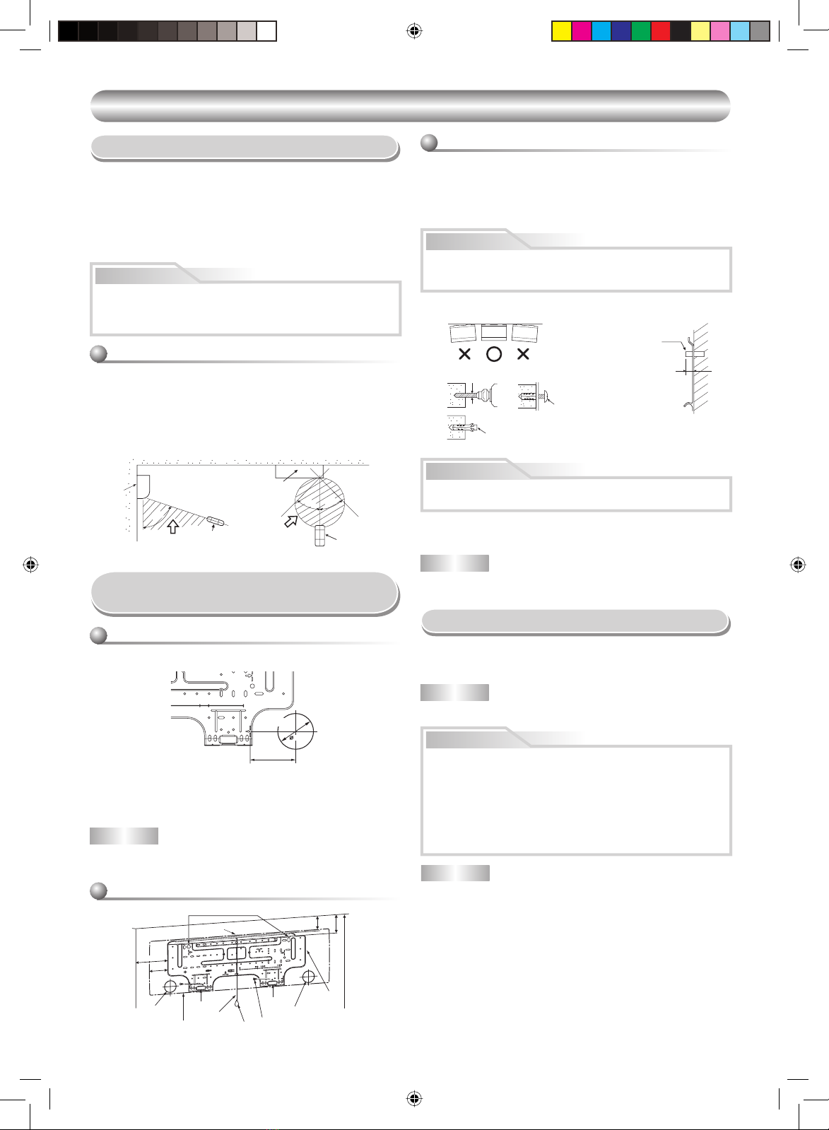
nCutting a Hole and Mounting Installation Plate .......................3
nElectrical Work ........................................................................3
nWiring Connection...................................................................4
nPiping and Drain Hose Installation ..........................................4
nIndoor Unit Fixing ....................................................................5
nDrainage..................................................................................5
OUTDOOR UNIT..........................................................................5
nInstallation Place .....................................................................5
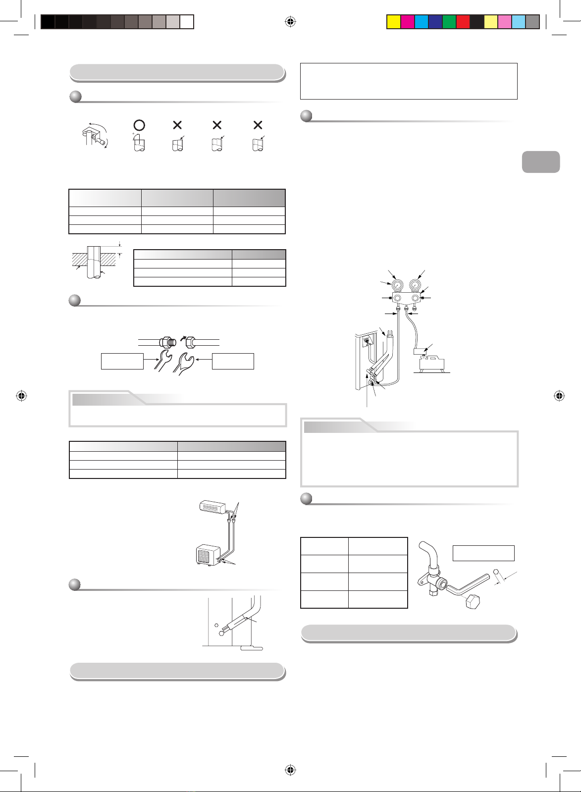
nRefrigerant Piping Connection ................................................6
nEvacuating ..............................................................................6
nWiring Connection...................................................................6
OTHERS.......................................................................................7
nGas Leak Test .........................................................................7
nRemote Control A-B Selection................................................. 7
nTest Operation ........................................................................7
nAuto Restart Setting ...............................................................7
PRECAUCIONES SOBRE SEGURIDAD ....................................1
DIAGRAMA DE INSTALACIÓN DE LA UNIDAD INTERIOR Y
EXTERIOR ...................................................................................2
nPiezas de Instalación Opcional ..............................................2
UNIDAD INTERIOR .....................................................................3
nLugar de Instalación................................................................3
nCorte de un Orificio y Montaje de la Placa de Instalación ......3
nTrabajo Eléctrico .....................................................................3
nConexión de Cables................................................................4
nInstalación la Tubería y el Tubo de Desagüe .........................4
nInstalación de la Unidad Interior..............................................5
nDrenaje ...................................................................................5
UNIDAD EXTERIOR ....................................................................5
nLugar de Instalación................................................................5
nConexión de la Tubería Refrigerante ......................................6
nEvacuación .............................................................................6
nConexión de Cables................................................................6
OTROS.........................................................................................7
nComprobación de Fugas.........................................................7
nMando a distancia A-B Selección............................................7
nPrueba de Operación .............................................................7
nAjuste de Reinicio Automático ................................................7
EN
CONTENIDOS
ES
SOMMAIRE
FR
MESURES DE SÉCURITÉ...........................................................1
PLAN D’INSTALLATION DES UNITÉS INTÉRIEURE ET
EXTÉRIEURE...............................................................................2
nPièces d’Installation en Option ...............................................2
UNITÉ INTÉRIEURE....................................................................3
nEndroit d’Installation................................................................3
nOuverture du Trou et Montage de la Plaque d’Installation .....3
nTravaux Electriques ................................................................3
nConnexion des Câbles ............................................................4
nInstallation de la Conduite et du Tuyau de Purge ...................4
nInstallation de l’Unité Intérieure...............................................5
nDrainage .................................................................................5
UNITÉ EXTÉRIEURE...................................................................5
nEndroit d’Installation................................................................5
nConnexion du Tuyau Réfrigérant.............................................6
nEvacuation ..............................................................................6
nConnexion des Câbles ............................................................6
AUTRES.......................................................................................7
nTest de Fuite Gaz ....................................................................7
nSélection de télécommande A-B ............................................. 7
nOpération du Test ................................................................... 7
nRéglage de la Remise en Marche Automatique .....................7
INDICE
PRECAUZIONI PER LA SICUREZZA.........................................1
SCHEMA DI INSTALLAZIONE DELL’ UNITÀ INTERNA
E DELL’ UNITÀ ESTERNA..........................................................2
nComponenti di Installazione Opzionali ...................................2
UNITÀ INTERNA .........................................................................3
nLuogo per l’Installazione..........................................................3
n
Apertura di un Foro e Installazione della Lastra di Installazione
...3
nLavori Elettrici..........................................................................3
nCollegamento dei Cavi ............................................................4
nInstallazione dei Tubi e del Tubo di Scarico ............................4
nInstallazione dell’Unità Interna ................................................5
nScarico ....................................................................................5
UNITÀ ESTERNA ........................................................................5
nLuogo per l’Installazione..........................................................5
nCollegamento dei Tubi del Refrigerante..................................6
nEvacuazione ...........................................................................6
nCollegamento dei Cavi ............................................................6
ALTRI ...........................................................................................7
nTest per Perdite di Gas............................................................7
nSelezione A-B del telecomando ..............................................7
nFunzionamento di Prova .........................................................7
nImpostazione per la Rimessa in Funzione Automatica ........... 7
IT
INHALT
SICHERHEITSVORKEHRUNGEN ..............................................1
EINBAUZEICHNUNGEN FÜR INNEN- UND
AUSSENGERÄT..........................................................................2
nZusätzlich erhältliche Installationsteile ...................................2
INNENGERÄT..............................................................................3
nAufstellungsort.........................................................................3
nMauerdurchbruch und Befestigung der Montageplatte ..........3
nElektrische Anschlüsse ...........................................................3
nKabelanschlüsse .....................................................................4
nInstallation von Leitungen und Kondensatschlauch ................4
nEinbau des Innengeräts ..........................................................5
nEntwässerung .........................................................................5
AUSSENGERÄT..........................................................................5
nAufstellungsort.........................................................................5
nAnschluß der Kühlmittelleitungen............................................6
nEntleeren ................................................................................6
nKabelanschlüsse .....................................................................6
SONSTIGES.................................................................................7
nÜberprüfung auf Gas-Undichtigkeit.........................................7
nFernbedienung A-B Wahl ........................................................7
nProbelauf.................................................................................7
nAutomatische Wiedereinschaltung..........................................7
DE
ÍNDICE
PRECAUÇÕES RELATIVAS A SEGURANÇA............................1
ESQUEMA DE INSTALAÇÃO DAS UNIDADES INTERIOR
E EXTERIOR................................................................................2
nPeças de Instalação Opcionais...............................................2
UNIDADE INTERIOR...................................................................3
nLocal de Instalação .................................................................3
nCortar um Orifício e Montar a Placa de Instalação .................3
nTrabalhos de Electricidade......................................................3
nLigações Eléctricas .................................................................4
nInstalação da Tubagem e do Tubo Flexível de Dreno.............4
nColocação da Unidade Interior................................................5
nDrenagem................................................................................5
UNIDADE EXTERIOR..................................................................5
nLocal de Instalação .................................................................5
nLigação das Condutas de Refrigeração..................................6
nPurga de Ar .............................................................................6
nLigações Eléctricas .................................................................6
OUTROS ......................................................................................7
nTeste de Fugas de Gás ...........................................................7
nSelecção A-B do telecomando ................................................7
nExecução do Teste .................................................................. 7
nDefinindo de Reiniciação Automática......................................7
PT
SPIS TREŚCI
ZASADY BEZPIECZEŃSTWA.....................................................1
SCHEMAT INSTALACYJNY URZĄDZENIA WEWNĘTRZNEGO
I ZEWNĘTRZNEGO.....................................................................2
nDodatkowe Części Instalacyjne...............................................2
URZĄDZENIE WEWNĘTRZNE ...................................................3
nMiejsce Instalacji .....................................................................3
nWycinanie Otworu oraz MontażPłyty Instalacyjnej.................3
nPrace Elektryczne ...................................................................3
nPodłączenie Okablowania.......................................................4
n
MontażInstalacji Rurowej i Węża do Odprowadzania Cieczy
..4
nMocowanie Urządzenia Wewnętrznego ..................................5
nOdprowadzanie Cieczy ...........................................................5
URZĄDZENIE ZEWNĘTRZNE ....................................................5
nMiejsce Instalacji .....................................................................5
nŁączenie Instalacji Rurowej Czynnika Chłodniczego ..............6
nUsuwanie Powietrza................................................................6
nPodłączenie Okablowania.......................................................6
INNE.............................................................................................7
nPróba Gazoszczelności...........................................................7
nUstawienia przełącznika A-B wyboru pilota.............................7
nPróba Działania.......................................................................7
n
Włączanie Funkcji Automatycznego Wznawiania Pracy (Auto Restart)
..7
PL
OBSAH
BEZPEČNOSTNÍ OPATŘENÍ ......................................................1
SCHÉMA INSTALACE VNITŘNÍ A VENKOVNÍ JEDNOTKY......2
nVolitelné Doplňky pro Instalaci ................................................2
VNITŘNÍ JEDNOTKA ..................................................................3
nMísto Instalace ........................................................................3
nVyvrtání Otvoru a Montáž Instalační Desky ............................3
nElektrické Práce ......................................................................3
nZapojení Vodičů.......................................................................4
nMontáž Trubek a Vypouštěcí Hadice.......................................4
nMontáž Vnitřní Jednotky..........................................................5
nOdvod Vody.............................................................................5
VENKOVNÍ JEDNOTKA..............................................................5
nMísto Instalace ........................................................................5
nSpojování Chladivového Potrubí.............................................6
nVyčerpávání Vzduchu.............................................................. 6
nZapojení Vodičů.......................................................................6
OSTATNĺ......................................................................................7
nZkouška Úniku Plynu...............................................................7
nVolba A-B na dálkovém ovládání............................................. 7
nZkušební Provoz .....................................................................7
nNastavení Automatického Znovuspuštění...............................7
CZ
SADRŽAJ
MJERE SIGURNOSTI..................................................................1
SHEMA UGRADNJE UNUTARNJIH I VANJSKIH JEDINICA.....2
nDodatni Dijelovi za Ugradnju Prema Izboru ...........................2
UNUTARNJA JEDINICA..............................................................3
nMjesto Ugradnje ......................................................................3
nIzrezivanje Rupe i Postavljanje Ploče za Ugradnju.................3
nElektrični Radovi......................................................................3
nŽičana Veza.............................................................................4
nUgradnja Cijevi i Crijeva za Pražnjenje ...................................4
nUčvršćivanje Unutarnje Jedinice .............................................5
nIspust.......................................................................................5
VANJSKA JEDINICA...................................................................5
nMjesto Ugradnje ......................................................................5
nSklop Cijevi Rashladnog Sredstva ..........................................6
nPražnjenje ...............................................................................6
nŽičana Veza.............................................................................6
OSTALO.......................................................................................7
nProba Isticanja Plina................................................................7
nOdabir A-B pomoću daljinskog upravljača...............................7
nProbni Rad ..............................................................................7
nPostava za Automatsko Ponovno Pokretanje .........................7
CR
TARTALOMJEGYZÉK
BIZTONSÁGI ELŐÍRÁSOK.........................................................1
BELTÉRI ÉS KÜLTÉRI EGYSÉGEK ÜZEMBE HELYEZÉSE.....2
nKülön RendelhetőAlkatrészek ................................................2
BELTÉRI EGYSÉG ......................................................................3
nA Felszerelés Helye.................................................................3
nLyuk Kivágása és a Felszerelése............................................3
nElektromos Munka...................................................................3
nKábelezés................................................................................4
nA Csövek és a KondenzvíztömlőFelszerelése .......................4
nA Beltéri Egység Rögzítése.....................................................5
nVízelvezetés............................................................................5
KÜLTÉRI EGYSÉG......................................................................5
nA Felszerelés Helye.................................................................5
nHűtőközegcső-csatlakozások..................................................6
nLégtelenítés ............................................................................6
nKábelezés................................................................................6
EGYEBEK....................................................................................7
nTömítettségvizsgálat ...............................................................7
nA távirányítón az A-B állás kiválasztása..................................7
nTesztüzem ...............................................................................7
nAutomatikus Újraindítás Beállítás............................................7
HU
INHOUDSOPGAVE
VEILIGHEIDSVOORZORGEN.....................................................1
INSTALLATIESCHEMA VOOR BINNEN- EN
BUITENMODULES ......................................................................2
nOptionele Onderdelen .............................................................2
BINNENMODULE ........................................................................3
nInstallatieplaats........................................................................3
nGat Boren en Montageplaat Bevestigen .................................3
nElektriciteit............................................................................... 3
nBedrading................................................................................4
nLeidingen en Afvoerslang Installeren ......................................4
nBinnenmodule Bevestigen.......................................................5
nAfvoer...................................................................................... 5
BUITENMODULE.........................................................................5
nInstallatieplaats........................................................................5
nKoelleidingsaansluiting............................................................6
nAfvoeren .................................................................................6
nBedrading................................................................................6
OVERIGE .....................................................................................7
nGaslektest ...............................................................................7
nAfstandsbediening keuze A-B .................................................7
nTestwerking .............................................................................7
nAutomatische Herstart Instellen ..............................................7
NL
ΠΕΡΙΕXOΜΕΝΑ
ΠΡOΦΥΛΑΞΕΙΣ ΑΣΦΑΛΕΙΑΣ.......................................................1
∆ΙΆΓΡΑΜΜΑ ΕΓΚΑΤΆΣΤΑΣΗΣ ΤΗΣ ΕΣΩΤΕΡΙΚΉΣ ΚΑΙ
ΕΞΩΤΕΡΙΚΉΣ ΜOΝΆ∆ΑΣ ..........................................................2
nΠροαιρετικά Eξαρτήµατα Eγκατάστασης...........................2
ΕΣΩΤΕΡΙΚΉ ΜOΝΆ∆Α...............................................................3
nΣηµείο Eγκατάστασης ..........................................................3
nΚψιµο Τρύ ας και Το οθέτηση Πλάτης Εγκατάστασης...3
nΗλεκτρικές Εργασίες............................................................3
nΣύνδεση Καλωδίωσης...........................................................4
n
Εγκατάσταση Σωλήνωσης και Eύκαµ του Σωλήνα A οστράγγισης
..4
nΣτερέωση Εσωτερικής Μoνάδας.........................................5
nΑ oστράγγιση........................................................................5
ΕΞΩΤΕΡΙΚΉ ΜOΝΆ∆Α...............................................................5
nΣηµείo Εγκατάστασης ..........................................................5
nΣύνδεση Ψυκτικών Σωληνώσεων........................................6
nΕκκένωση...............................................................................6
nΣύνδεση Καλωδίωσης...........................................................6
ΛOΙΠΑ ..........................................................................................7
nΈλεγχoς ∆ιαρρoής Αερίoυ................................................... 7
nΕ ιλογή Α-Β τoυ τηλεχειριστηρίoυ.....................................7
n∆oκιµή Λειτoυργίας .............................................................. 7
nAuto Restart Ρύθµιση ...........................................................7
GR
Cover 1110251217.indd 2Cover 1110251217.indd 2 1/13/10 4:49:28 PM1/13/10 4:49:28 PM

INNEHÅLLSLFÖRTECKNING
SÄKERHETSANVISNINGAR ......................................................1
INSTALLATIONSSCHEMA FÖR INOMHUS- OCH
UTOMHUSENHETEN ..................................................................2
nValfria installationskomponenter..............................................2
INOMHUSENHETEN ...................................................................3
nPlats för montering .................................................................. 3
nSkära ut ett hål och fästa monteringsplåten............................3
nElarbeten.................................................................................3
nLedningsdragningar.................................................................4
nInstallera rör och dräneringsslang...........................................4
nFästa inomhusenheten............................................................5
nDränering.................................................................................5
UTOMHUSENHETEN ..................................................................5
nPlats för montering .................................................................. 5
nAnslutning av köldmedierör.....................................................6
nVakuumsugning.......................................................................6
nLedningsdragningar.................................................................6
ÖVRIGT........................................................................................7
nKontrollera gasläckor...............................................................7
nFjärrkontroll A-B Val.................................................................7
nTestkörning ..............................................................................7
nInställning av omstart ..............................................................7
SV
SISÄLLYSLUETTELO
VAROTOIMENPITEET.................................................................1
SISÄ- JA ULKOYKSIKKÖJEN ASENNUSKAAVIO....................2
nLisävarusteena saatavat asennusosat....................................2
SISÄYKSIKKÖ.............................................................................3
nAsennuspaikka........................................................................3
nAukon tekeminen ja asennuslevyn kiinnittäminen...................3
nSähkötyöt ................................................................................3
nJohtoliitännät ...........................................................................4
nPutkiston ja tyhjennysletkun asentaminen ..............................4
nSisäyksikön kiinnittäminen ......................................................5
nVedenpoisto.............................................................................5
ULKOYKSIKKÖ...........................................................................5
nAsennuspaikka........................................................................5
nKylmänesteputkien liittäminen.................................................6
nTyhjentäminen.........................................................................6
nJohtoliitännät ...........................................................................6
MUUT ...........................................................................................7
nKaasuvuototesti.......................................................................7
nKauko-ohjaimen A-B valinta ....................................................7
nKoekäyttö ................................................................................7
nAutomaattisen uudelleenkäynnistyksen asettaminen..............7
FI
INNHOLDSFORTEGNELSE
SIKKERHETSREGLER ...............................................................1
KOBLINGSSKJEMA FOR INNE- OG UTENDØRSENHETEN ...2
nEkstrautstyr .............................................................................2
INNENHETEN ..............................................................................3
nPlassering................................................................................3
nLage et Hull og Montere Montasjeplaten.................................3
nElektrisk Arbeid........................................................................3
nTilkobling av Ledninger............................................................4
nInstallasjon av Rør og Avløpsslange .......................................4
nPlassering av Innendørsenheten.............................................5
nAvløp .......................................................................................5
UTENDØRSENHET .....................................................................5
nMontasjested...........................................................................5
nTilkobling av Kjølerørene.........................................................6
nEvakuering ..............................................................................6
nTilkobling av Ledninger............................................................6
ANNET .........................................................................................7
nGasslekkasjetest .....................................................................7
nFjernkontroll A-B valg ..............................................................7
nTestdrift....................................................................................7
nInnstillinger for Auto Restart ....................................................7
NO
INDHOLD
SIKKERHEDSFORHOLDSREGLER...........................................1
INSTALLATIONSDIAGRAM FOR INDDØRS OG UDENDØRS
ENHED.........................................................................................2
nValgfrie installationsdele..........................................................2
INDENDØRS ENHED ..................................................................3
nInstallationssted.......................................................................3
nSkæring af et hul og montering af installationspladen.............3
nElektrisk arbejde......................................................................3
nTilslutning af kabel...................................................................4
nInstallation af rør og drænrør...................................................4
nFastsætning af den indendørs enhed......................................5
nDræning...................................................................................5
UDENDØRS ENHED ...................................................................5
nInstallationssted.......................................................................5
nKølerørsforbindelsen...............................................................6
nEvakuering ..............................................................................6
nTilslutning af kabel...................................................................6
ANDET .........................................................................................7
nGaslækagekontrol ...................................................................7
nValg af fjernbetjening A-B ........................................................7
nTestdrift ...................................................................................7
nAuto-omstartsindstilling ...........................................................7
DK
CONŢINUT
MĂSURI DE SIGURANŢĂ...........................................................1
SCHEMA DE INSTALARE A UNITĂŢILOR INTERIOARĂŞI
EXTERIOARĂ..............................................................................2
nPiese de instalare opţionale ....................................................2
UNITATE INTERIOARĂ...............................................................3
nLocul de instalare ....................................................................3
nExecutarea unei găuri şi montarea plăcii de instalare.............3
nLucrările electrice ....................................................................3
nRacordarea cablurilor..............................................................4
nInstalarea ţevilor şi a furtunului de evacuare...........................4
nFixarea unităţii interioare.........................................................5
nEvacuarea ...............................................................................5
UNITATEA EXTERIOARĂ...........................................................5
nLocul de instalare ....................................................................5
nRacordarea ţevilor de lichid refrigerent ...................................6
nEvacuarea ..............................................................................6
nRacordarea cablurilor..............................................................6
ALTELE........................................................................................7
nVerificarea scurgerilor de gaz................................................. 7
nAlegerea telecomenzii A-B ......................................................7
nVerificarea funcţionării.............................................................7
nSetarea Auto Restart (repornirea automată) ...........................7
RO
СЪДЪРЖАНИЕ
ПРЕДПАЗНИ МЕРКИ ЗА БЕЗОПАСНОСТ ..............................1
ДИАГРАМА ЗА ИНСТАЛИРАНЕ НА ВЪТРЕШНИЯТ И
ВЪНШНИЯТ МОДУЛ .................................................................2
nДопълнителни елементи за монтаж....................................2
ВЪТРЕШЕН МОДУЛ ..................................................................3
nМясто за монтаж...................................................................3
n
Пробиване на отвор и монтиране на монтажната планка
..3
nРабота по електри еската система.....................................3
nСвързване на кабелите........................................................4
nИнсталиране на тръбите и гъвкавата дренажна тръба ....4
nФиксиране на вътрешния модул..........................................5
nДренаж ...................................................................................5
ВЪНШЕН МОДУЛ ......................................................................5
nМясто за монтаж...................................................................5
nСвързване на тръбите за хладилния агент........................6
nСъздаване на вакуум ...........................................................6
nСвързване на кабелите........................................................6
ДРУГИ..........................................................................................7
nТест за нали ие на газови те ове........................................7
nИзбиране на настройки „А” или „В” на дистанционното
управление.............................................................................7
nТестов режим .........................................................................7
nНастройка за автомати но рестартиране .........................7
BG
SISUKORD
OHUTUSABINÕUD......................................................................1
SISE- JA VÄLISSEADMETE PAIGALDUSSKEEM ....................2
nValikulised paigaldusdetailid....................................................2
SISESEADE.................................................................................3
nPaigalduskoht..........................................................................3
nAugu tegemine ja paigaldusplaadi monteerimine....................3
nElektrilised tööd.......................................................................3
nKaablite ühendamine...............................................................4
nTorustiku ja äravooluvooliku paigaldamine..............................4
nSiseseadme parandamine.......................................................5
nÄravool ....................................................................................5
VÄLISSEADE...............................................................................5
nPaigalduskoht..........................................................................5
nJahutussegu torustiku ühendamine.........................................6
nTühjendamine .........................................................................6
nKaablite ühendamine...............................................................6
MUU .............................................................................................7
nGaasilekke test........................................................................7
nKaugjuhtimispuldi A- ja B-sätted.............................................. 7
nTestfunktsioon .........................................................................7
nAutomaatse taaskäivitamise säte............................................7
EE
SATURS
PROFILAKTISKIE DROŠĪBAS PASĀKUMI ...............................1
IEKŠTELPAS UN ĀRA AGREGĀTA MONTĀŽAS SHĒMA........2
nPapildaprīkojuma montāžas daļas .........................................2
IEKŠTELPAS AGREGĀTS..........................................................3
nMontāžas vieta ........................................................................3
nCauruma izveide un montāžas plāksnes uzstādīšana............3
nElektroinstalācijas darbi...........................................................3
nKabeļu savienojumi .................................................................4
nCauruļu un drenāžas šļūtenes uzstādīšana............................4
nIekštelpas agregāta piestiprināšana........................................5
nDrenāža...................................................................................5
ĀRA AGREGĀTS.........................................................................5
nMontāžas vieta ........................................................................5
nAukstumaģenta cauruļu savienojumi.......................................6
nIzsūknēšana ............................................................................6
nKabeļu savienojumi .................................................................6
PAPILDINFORMĀCIJA................................................................7
nGāzes noplūdes pārbaude ......................................................7
nTālvadības pults režīma A/B izvēle......................................... 7
nDarbības pārbaude .................................................................7
nDarbības automātiskās atsākšanas funkcijas iestatīšana ......7
LV
OBSAH
BEZPEČNOSTNÉ ZÁSADY ........................................................1
INŠTALAČNÁ SCHÉMA VNÚTORNEJ A VONKAJŠEJ JEDNOTKY
..2
nVoliteľné inštalačné diely .........................................................2
VNÚTORNÁ JEDNOTKA ............................................................3
nMiesto inštalácie......................................................................3
nZhotovenie diery a montáž inštalačnej lišty.............................3
nElektroinštalačná práca...........................................................3
nPripojenie vodičov ...................................................................4
nInštalácia rúrok a odvodňovacej hadice ..................................4
nUpevnenie vnútornej jednotky.................................................5
nOdvodňovanie .........................................................................5
VONKAJŠIA JEDNOTKA............................................................5
nMiesto inštalácie......................................................................5
nSpájanie chladiacich rúrok ......................................................6
nVyčerpanie vzduchu ................................................................ 6
nPripojenie vodičov ...................................................................6
INÉ................................................................................................7
nTest unikania plynu..................................................................7
nVoľba A-B na diaľkovom ovládači ............................................7
nTestovacia prevádzka..............................................................7
nNastavenie automatického reštartu.........................................7
SK
VSEBINA
VARNOSTNI UKREPI..................................................................1
NAMESTITVENA SHEMA NOTRANJE IN ZUNANJE ENOTE...2
nIzbirni namestitveni deli...........................................................2
NOTRANJA ENOTA ....................................................................3
nMesto za namestitev ...............................................................3
nRezanje luknje in montaža namestitvene plošče ....................3
nElektričarsko delo....................................................................3
nPriključitev napeljave...............................................................4
nNamestitev odvodne in ostalih cevi.........................................4
nPritrditev notranje enote ..........................................................5
nOdvajanje ................................................................................5
ZUNANJA ENOTA .......................................................................5
nMesto za namestitev ...............................................................5
nPriključitev hladilnih cevi..........................................................6
nIzčrpavanje .............................................................................6
nPriključitev napeljave...............................................................6
DRUGO ........................................................................................7
nPreizkus uhajanja plina ...........................................................7
nIzbira nastavitve A-B na daljinskem upravljalniku.................... 7
nPreizkus delovanja ..................................................................7
nNastavitev za samodejni ponovni zagon.................................7
SI
Cover 1110251217.indd 3Cover 1110251217.indd 3 1/13/10 4:49:30 PM1/13/10 4:49:30 PM

1
PRECAUTIONS FOR SAFETY
New refrigerant air conditioner installation
This appliance must be connected to the main power supply by means of a circuit breaker or a switch with a contact separation of at least 3 mm in all poles.
The installation fuse (25A) must be used for the power supply line of this air conditioner.
To disconnect the appliance from the main power supply
REQUIREMENT OF REPORT TO THE LOCAL POWER SUPPLIER
Please make absolutely sure that the installation of this appliance is reported to the local power supplier before installation. If you experience any problems
or if the installation is not accepted by the supplier, the service agency will take adequate countermeasures.
CAUTION
WARNING
DANGER
CAUTION
CAUTION
• Never modify this unit by removing any of the safety guards or bypassing any of the safety interlock switches.
• Do not install in a place which cannot bear the weight of the unit.
Personal injury and property damage can result if the unit falls.
• Before doing the electrical work, attach an approved plug to the power supply cord.
Also, make sure the equipment is properly earthed.
• Appliance shall be installed in accordance with national wiring regulations.
If you detect any damage, do not install the unit. Contact your TOSHIBA dealer immediately.
• THIS AIR CONDITIONER USES THE NEW HFC REFRIGERANT (R410A), WHICH DOES NOT DESTROY THE OZONE LAYER.
R410A refrigerant is apt to be affected by impurities such as water, oxidizing membranes, and oils because the pressure of R410A refrigerant is approx.
1.6 times of refrigerant R22. As well as the adoption of this new refrigerant, refrigerating machine oil has also been changed. Therefore, during installation
work, be sure that water, dust, former refrigerant, or refrigerating machine oil does not enter the refrigeration cycle of a new-refrigerant air conditioner.
To avoid mixing refrigerant and refrigerating machine oil, the sizes of charging port connecting sections on the main unit are different from those for the
conventional refrigerant, and different size tools are also required. For connecting pipes, use new and clean piping materials with highpressure withstand
capabilities, designed for R410A only, and ensure that water or dust does not enter. Moreover, do not use any existing piping as its pressure withstand
may be insufficient and may contain impurities.
• FOR USE BY QUALIFIED PERSONS ONLY.
• TURN OFF MAIN POWER SUPPLY BEFORE ATTEMPTING ANY ELECTRICAL WORK. MAKE SURE ALL POWER SWITCHES ARE OFF.
FAILURE TO DO SO MAY CAUSE ELECTRIC SHOCK.
• CONNECT THE CONNECTING CABLE CORRECTLY. IF THE CONNECTING CABLE IS CONNECTED WRONGLY, ELECTRIC PARTS MAY BE
DAMAGED.
• CHECK THE EARTH WIRE THAT IT IS NOT BROKEN OR DISCONNECTED BEFORE INSTALLATION.
• DO NOT INSTALL NEAR CONCENTRATIONS OF COMBUSTIBLE GAS OR GAS VAPORS.
FAILURE TO FOLLOW THIS INSTRUCTION CAN RESULT IN FIRE OR EXPLOSION.
• TO PREVENT OVERHEATING THE INDOOR UNIT AND CAUSING A FIRE HAZARD, PLACE THE UNIT WELL AWAY (MORE THAN 2 M) FROM HEAT
SOURCES SUCH AS RADIATORS, HEATERS, FURNACE, STOVES, ETC.
• WHEN MOVING THE AIR CONDITIONER FOR INSTALLING IT IN ANOTHER PLACE AGAIN, BE VERY CAREFUL NOT TO GET THE SPECIFIED
REFRIGERANT (R410A) WITH ANY OTHER GASEOUS BODY INTO THE REFRIGERATION CYCLE. IF AIR OR ANY OTHER GAS IS MIXED IN THE
REFRIGERANT, THE GAS PRESSURE IN THE REFRIGERATION CYCLE BECOMES ABNORMALLY HIGH AND IT RESULTINGLY CAUSES BURST OF
THE PIPE AND INJURIES ON PERSONS.
• IN THE EVENT THAT THE REFRIGERANT GAS LEAKS OUT OF THE PIPE DURING THE INSTALLATION WORK, IMMEDIATELY LET FRESH AIR INTO
THE ROOM. IF THE REFRIGERANT GAS IS HEATED BY FIRE OR SOMETHING ELSE, IT CAUSES GENERATION OF POISONOUS GAS.
• Exposure of unit to water or other moisture before installation could result in electric shock.
Do not store it in a wet basement or expose to rain or water.
• After unpacking the unit, examine it carefully for possible damage.
• Do not install in a place that can increase the vibration of the unit. Do not install in a place that can amplify the noise level of the unit or where noise and
discharged air might disturb neighbors.
• To avoid personal injury, be careful when handling parts with sharp edges.
• Please read this installation manual carefully before installing the unit. It contains further important instructions for proper installation.
For general public use
Power supply cord of parts of appliance for outdoor use shall be at least polychloroprene sheathed flexible cord (design H07RN-F) or cord designation 245
IEC66 (2.0 mm2or more). (Shall be installed in accordance with national wiring regulations.)
1110251217-EN.indd 11110251217-EN.indd 1 2/3/10 10:46:43 AM2/3/10 10:46:43 AM

EN
ES
FR
IT
DE
PT
PL
CZ
RU
CR
HU
TR
NL
GR
SV
FI
NO
DK
RO
BG
EE
LV
SK
SI
2
INSTALLATION DIAGRAM OF INDOOR AND OUTDOOR UNITS
Part
code Parts name Q’ty
A
Refrigerant piping
Liquid side : Ø6.35 mm
Gas side : Ø12.70 mm
One
each
BPipe insulating material
(polyethylene foam, 6 mm thick) 1
CPutty, PVC tapes One
each
Optional Installation Parts
• Secure the outdoor unit with fixing bolts and nuts if the unit is likely to be
exposed to a strong wind.
• Use Ø8 mm or Ø10 mm anchor bolts and nuts.
• If it is necessary to drain the defrost water, attach drain nipple 9and cap
water proof !to the bottom plate of the outdoor unit before installing it.
Fixing bolt arrangement of outdoor unit
Insulate the refrigerant pipes separately
with insulation, not together.
2
38
6
4
Insert the cushion between the indoor
unit and wall, and tilt the indoor unit for
better operation.
For the rear left and left piping
Wall
Make sure to run the drain hose sloped
downward.
Do not allow the drain hose to get slack.
Cut the piping
hole sloped
slightly.
The auxiliary piping can be connected to
the left, rear left, rear right, right, bottom
right or bottom left.
Right
Rear
right
Bottom
right
Rear
left Bottom left
Left
6 mm thick heat resisting
polyethylene foam
1
Batteries
Pan head
wood screw Remote control holder
Vinyl tape
Apply after carrying
out a drainage test.
Wireless remote control
Saddle
Extension
drain hose
(Not available,
provided by installer)
Shield pipe
Filter
(Attach to the front panel.)
Air filter
Hook Installation
plate
Hook
65 mm or more
170 mm or more
170 mm or more
600 mm or more
100 mm or more
100 mm or more
600 mm or more
600 mm or more
Remark :
• Detail of accessory and installation parts can see in the accessory
sheet.
• Some pictures might be different from the actual parts.
5Filter
600 mm
90 mm
125 mm
108 mm
28 mm
86 mm
102 mm
320 mm
25 mm
Drain outlet
Air inlet
Air outlet
1110251217-EN.indd 21110251217-EN.indd 2 2/3/10 10:46:44 AM2/3/10 10:46:44 AM

3
INDOOR UNIT
INDOOR UNIT
Installation Place
• Direct sunlight to the indoor unit’s wireless receiver should be avoided.
• The microprocessor in the indoor unit should not be too close to RF
noise sources.
(For details, see the owner’s manual.)
Remote control
• A place where there are no obstacles such as a curtain that may block the
signal from the indoor unit
• Do not install the remote control in a place exposed to direct sunlight or close
to a heating source such as a stove.
• Keep the remote control at least 1 m apart from the nearest TV set or stereo
equipment. (This is necessary to prevent image disturbances or noise
interference.)
• The location of the remote control should be determined as shown below.
Cutting a Hole and Mounting
Installation Plate
NOTE
• When drilling a wall that contains a metal lath, wire lath or metal plate, be sure
to use a pipe hole brim ring sold separately.
Cutting a hole
When installing the refrigerant pipes from the rear
Mounting the installation plate
When the installation plate is directly mounted
on the wall
1. Securely fit the installation plate onto the wall by screwing it in the upper and
lower parts to hook up the indoor unit.
2. To mount the installation plate on a concrete wall with anchor bolts, use the
anchor bolt holes as illustrated in the below figure.
3. Install the installation plate horizontally in the wall.
When installing the installation plate with a mounting screw, do not use the
anchor bolt holes. Otherwise, the unit may fall down and result in personal
injury and property damage.
1. After determining the pipe hole position on the mounting plate (¨), drill the
pipe hole (Ø65 mm) at a slight downward slant to the outdoor side.
• A place which provides the spaces around the indoor unit as shown in the
diagram
• A place where there are no obstacles near the air inlet and outlet
• A place which allows easy installation of the piping to the outdoor unit
• A place which allows the front panel to be opened
• The indoor unit shall be installed as top of the indoor unit comes to at least
2 m height. Also, it must be avoided to put anything on the top of the indoor
unit.
CAUTION
54 °
45°
5
7°
(Side view) (Top view)
Indoor unit
Reception range
Remote
control
Remote
control
Reception
range
Indoor unit
65 mm
100 mm
80 100 180
The center of the pipe hole
is above the arrow.
Pipe hole
CAUTION
Electrical Work
1. The supply voltage must be the same as the rated voltage of the air condi-
tioner.
2. Prepare the power source for exclusive use with the air conditioner.
NOTE
• Wire type : More than H07RN-F or 245 IEC66
Failure to firmly install the unit may result in personal injury and property
damage if the unit falls.
• In case of block, brick, concrete or similar type walls, make 5 mm dia. holes
in the wall.
• Insert clip anchors for appropriate mounting screws 7.
NOTE
• Secure four corners and lower parts of the installation plate with 4 to 6
mounting screws to install it.
Installation plate
(Keep horizontal direction.)
Projection
15 mm or less
Anchor bolt
Clip anchor
(local parts)
5 mm dia. hole
Mounting screw
Ø4 x 25R
7
CAUTION
62
85
82.5
170
1
7
Anchor bolt holes
Hook
Hook Hook
Pipe hole Pipe hole
Installation
plate
Mounting screw
Weight
Indoor unit
Thread
2 m or more from floor
NOTE
• Perform wiring works so as to allow a general wiring capacity.
• This appliance can be connected to the mains in either of the following
two ways.
(1) Connection to fixed wiring:
A switch or circuit breaker which disconnects all poles and has a
contact separation of at least 3 mm must be incorporated in the fixed
wiring. An approved circuit breaker or switches must be used.
(2) Connection with power supply plug:
Attach power supply plug with power cord and plug it into wall outlet.
An approved power supply cord and plug must be used.
CAUTION
1110251217-EN.indd 31110251217-EN.indd 3 2/3/10 10:46:46 AM2/3/10 10:46:46 AM

EN
ES
FR
IT
DE
PT
PL
CZ
RU
CR
HU
TR
NL
GR
SV
FI
NO
DK
RO
BG
EE
LV
SK
SI
4
Rear right
Rear left
g
nittuc-eiD
tilsl
e
na
p
t
n
o
rf
g
n
i
gn
a
hC
e
s
ohniard
noitaraperpg
ni
p
i
P
Bottom left
Left
Bottom right
Right
Piping and Drain Hose Installation
* Since dewing results in a machine trouble, make sure to insulate both
connecting pipes. (Use polyethylene foam as insulating material.)
Piping and drain hose forming
1. Die-cutting front panel slit
Cut out the slit on the leftward or right side of the front panel for the left or
right connection and the slit on the bottom left or right side of the front panel
for the bottom left or right connection with a pair of nippers.
2. Changing drain hose
For leftward connection, bottom-leftward connection and rearleftward
connection’s piping, it is necessary to change the drain hose and drain
cap.
How to remove the drain cap
Clip the drain cap by needle-
nose pliers and pull out.
Heat insulator
Drain hose
How to remove the drain hose
• The drain hose can be removed by removing the
screw securing the drain hose and then pulling out
the drain hose.
• When removing the drain hose, be careful of any
sharp edges of steel plate. The edges can injuries.
• To install the drain hose, insert the drain hose
firmly until the connection part contacts with heat
insulator, and the secure it with original screw.
How to fix the drain cap
1) Insert hexagon
wrench (4 mm)
in a center head.
4 mm
2) Firmly insert the drain cap.
Do not apply lubricating oil
(refrigerant machine oil) when
inserting the drain cap. Application
causes deterioration and drain
leakage of the plug.
Insert a hexagon
wrench (4 mm).
No gap
Firmly insert the drain hose and drain cap; otherwise, water may leak.
In case of right or left piping
• After scribing slits of the front panel with a
knife or a making-off pin, cut them with a
pair of nippers or an equivalent tool.
In case of bottom right or bottom left piping
• After scribing slits of the front panel with a
knife or a making-off pin, cut them with a
pair of nippers or an equivalent tool.
Slit
Slit
Left-hand connection with piping
• Bend the connecting pipe so that it is laid within 43 mm above the wall
surface. If the connecting pipe is laid exceeding 43 mm above the wall
surface, the indoor unit may unstably be set on the wall.
When bending the connecting pipe, make sure to use a spring bender so as
not to crush the pipe.
Bend the connecting pipe within a radius of 30 mm.
To connect the pipe after installation of the unit (figure)
How to install the air inlet grille on the indoor
unit
• When attaching the air inlet grille,
the contrary of the removed
operation is performed.
Wiring Connection
Wiring of the connecting cable can be carried out without removing the
front panel.
1. Remove the air inlet grille.
Open the air inlet grille upward and pull it toward you.
2. Remove the terminal cover and cord clamp.
3. Insert the connecting cable (according to the local cords) into the pipe hole
on the wall.
4. Take out the connecting cable through the cable slot on the rear panel so
that it protrudes about 15 cm from the front.
5. Insert the connecting cable fully into the terminal block and secure it tightly
with screws.
6. Tightening torque : 1.2 N·m (0.12 kgf·m)
7. Secure the connecting cable with the cord clamp.
8. Fix the terminal cover, rear plate bushing and air inlet grille on the indoor
unit.
How to connect the connecting cable
• Be sure to refer to the wiring system diagram labeled inside the front
panel.
• Check local electrical cords and also any specific wiring instructions or
limitations.
NOTE
• Use stranded wire only.
• Wire type : H07RN-F or more
CAUTION
CAUTION
10 mm
10 mm
50 mm
110 mm
Cord clamp Terminal block
Terminal cover
Screw
Earth line
Screw Connecting cable
Screw
Earth line
Connecting cable
Stripping length of the connecting cable
about 15 cm
80
270 mm
230 mm
m
m3
4
Liquid side
Gas side
(To the forefront of flare)
Outward form of indoor unit
R 30 mm (Use polisin (polyethylene)
core or the like for bending pipe.)
Use the handle of screwdriver, etc.
1110251217-EN.indd 41110251217-EN.indd 4 2/3/10 10:46:47 AM2/3/10 10:46:47 AM

5
NOTE
If the pipe is bent incorrectly, the indoor unit may unstably be set on the wall.
After passing the connecting pipe through the pipe hole, connect the
connecting pipes to the auxiliary pipes and wrap the facing tape around
them.
CAUTION
Indoor Unit Fixing
• For detaching the indoor unit from the
installation plate, pull the indoor unit
toward you while pushing its bottom up
at the specified parts.
PushPush
Press
(unhook)
Hook
Hook here.
1
2
Installation plate
1
1. Pass the pipe through the hole in the wall and hook the indoor unit on the
installation plate at the upper hook.
2. Swing the indoor unit to right and left to confirm that it is firmly hooked up on
the installation plate.
3. While pressing the indoor unit onto the wall, hook it at the lower part on the
installation plate. Pull the indoor unit toward you to confirm that it is firmly
hooked up on the installation plate.
Drainage
1. Run the drain hose sloped downwards.
2. Put water in the drain pan and make sure that the water is drained out of
doors.
3. When connecting extension drain hose, insulate the connecting part of
extension drain hose with shield pipe.
NOTE
• The hole should be made at a slight downward slant on the outdoor side.
50 mm
or more
Do not put the
drain hose end
into water.
Do not put the
drain hose end
in the drainage ditch.
Do not form the
drain hose into
a wavy shape.
Do not rise the
drain hose.
Extension drain hose
Inside the room
Drain hose
Shield pipe
Arrange the drain pipe for proper drainage from the unit.
Improper drainage can result in dew-dropping.
This air conditioner has the structure designed
to drain water collected from dew, which forms
on the back of the indoor unit, to the drain pan.
Therefore, do not store the power cord and other
parts at a height above the drain guide.
CAUTION
OUTDOOR UNIT
OUTDOOR UNIT
Installation Place
• A place which provides the spaces around the outdoor unit as shown in the
diagram
• A place which can bear the weight of the outdoor unit and does not allow an
increase in noise level and vibration
• A place where the operation noise and discharged air do not disturb your
neighbors
• A place which is not exposed to a strong wind
• A place free of a leakage of combustible gases
• A place which does not block a passage
• When the outdoor unit is to be installed in an elevated position, be sure to
secure its feet.
• The allowable pipe length is up to 20 m. If the length is over 15 m, add 20 g
of refrigerant for every additional meter of the pipe length.
• The allowable height of outdoor-unit installation site is up to 10 m.
• A place where the drain water does not raise any problems
CAUTION
1. Install the outdoor unit without anything blocking the air discharging.
2. When the outdoor unit is installed in a place always exposed to strong
wind like a coast or on a high storey of a building, secure the normal fan
operation using a duct or a windshield.
3. In particularly windy areas, install the unit such as to avoid admission of
wind.
4. Installation in the following places may result in trouble.
Do not install the unit in such places.
• A place full of machine oil
• A saline-place such as the coast
• A place full of sulfide gas
• A place where high-frequency
waves are likely to be generated
as from audio equipment, welders,
and medical equipment
Strong
wind
• Bind the auxiliary pipes (two) and connecting cable with facing tape
tightly. In case of leftward piping and rear-leftward piping, bind the
auxiliary pipes (two) only with facing tape.
Auxiliary pipes
Indoor unit
Connecting cable
Installation plate
• Carefully arrange pipes so that any pipe does not stick out of the rear
plate of the indoor unit.
• Carefully connect the auxiliary pipes and connecting pipes to one
another and cut off the insulating tape wound on the connecting pipe to
avoid double-taping at the joint; moreover, seal the joint with the vinyl
tape, etc.
• Since dewing results in a machine trouble, make sure to insulate both
connecting pipes. (Use polyethylene foam as insulating material.)
• When bending a pipe, carefully do it, not to crush it.
Wall
Drain
guide
Space for pipes
1110251217-EN.indd 51110251217-EN.indd 5 2/3/10 10:46:49 AM2/3/10 10:46:49 AM

EN
ES
FR
IT
DE
PT
PL
CZ
RU
CR
HU
TR
NL
GR
SV
FI
NO
DK
RO
BG
EE
LV
SK
SI
6
CAUTION
Refrigerant Piping Connection
1. Cut the pipe with a pipe cutter.
2. Insert a flare nut into the pipe and flare the pipe.
• Projection margin in flaring : A (Unit : mm)
Rigid (clutch type)
Obliquity Roughness Warp
90
Imperial (wing nut type)
Outer dia. of copper pipe R410A
6.35 1.5 to 2.0
9.52 1.5 to 2.0
12.70 2.0 to 2.5
Die Pipe
A
Align the centers of the connecting pipes and tighten the flare nut as far as
possible with your fingers. Then tighten the nut with a spanner and torque
wrench as shown in the figure.
Tightening connection
Do not apply excess torque. Otherwise, the nut may crack depending on
the conditions.
(Unit : N·m)
Outer dia. of copper pipe Tightening torque
Ø6.35 mm 16 to 18 (1.6 to 1.8 kgf·m)
Ø9.52 mm 30 to 42 (3.0 to 4.2 kgf·m)
Ø12.70 mm 50 to 62 (5.0 to 6.2 kgf·m)
Evacuating
After the piping has been connected to the indoor unit, you can perform the
air purge together at once.
AIR PURGE
Evacuate the air in the connecting pipes and in the indoor unit using a
vacuum pump. Do not use the refrigerant in the outdoor unit. For details,
see the manual of the vacuum pump.
Outer dia.
of copper pipe R410A tool used Conventional tool
used
6.35 0 to 0.5 1.0 to 1.5
9.52 0 to 0.5 1.0 to 1.5
12.70 0 to 0.5 1.0 to 1.5
Use a wrench to secure. Use a torque wrench to tighten.
Flare nut
Half union
Internally
threaded side
Externally
threaded side
• Tightening torque of flare pipe connections
Flare at
indoor unit side
Flare at
outdoor unit side
The operating pressure of R410A
is higher than that of R22 (approx.
1.6 times). It is therefore necessary
to firmly tighten the flare pipe
connecting sections (which connect
the indoor and outdoor units) up to the
specified tightening torque. Incorrect
connections may cause not only a
gas leakage, but also damage to the
refrigeration cycle.
1. How to shape the pipes
Shape the pipes along the incused line on
the outdoor unit.
2. How to fit position of the pipes
Put the edges of the pipes to the place with
a distance of 85 mm from the incused line.
Shaping pipes
Incused line
Flaring
Be sure to use a vacuum pump with counter-flow prevention function so that
inside oil of the pump does not flow backward into pipes of the air conditioner
when the pump stops.
(If oil inside of the vacuum pump enters the air conditioner, which use R410A,
refrigeration cycle trouble may result.)
1. Connect the charge hose from the manifold valve to the service port of the
packed valve at gas side.
2. Connect the charge hose to the port of the vacuum pump.
3. Open fully the low pressure side handle of the gauge manifold valve.
4. Operate the vacuum pump to start evacuating. Perform evacuating for about
15 minutes if the piping length is 20 meters. (15 minutes for 20 meters)
(assuming a pump capacity of 27 liters per minute) Then confirm that the
compound pressure gauge reading is –101 kPa (–76 cmHg).
5. Close the low pressure side valve handle of the gauge manifold valve.
6. Open fully the valve stem of the packed valves (both gas and liquid sides).
7. Remove the charging hose from the service port.
8. Securely tighten the caps on the packed valves.
Using a vacuum pump
Packed valve at liquid side
Service port (Valve core (Setting pin))
Packed valve at gas side
Vacuum
pump
Vacuum pump adapter for
counter-flow prevention
(For R410A only)
Charge hose
(For R410A only)
Handle Hi
(Keep full closed)
Manifold valve
Pressure gauge
Compound pressure gauge
Handle Lo
Charge hose
(For R410A only)
Connecting pipe
–101 kPa
(–76 cmHg)
• Open the valve stem all the way out, but do not try to open it beyond the
stopper.
• Securely tighten the valve stem cap with torque in the following table:
Packed valve handling precautions
m
m4
The hexagon wrench
is required.
Gas side
(Ø12.70 mm)
50 to 62 N·m
(5.0 to 6.2 kgf·m)
Gas side
(Ø9.52 mm)
30 to 42 N·m
(3.0 to 4.2 kgf·m)
Liquid side
(Ø6.35 mm)
16 to 18 N·m
(1.6 to 1.8 kgf·m)
Service port 9 to 10 N·m
(0.9 to 1.0 kgf·m)
Wiring Connection
1. Remove the valve cover from the outdoor unit.
2. Connect the connecting cable to the terminals as identified with their
respective matched numbers on the terminal block of indoor and outdoor
unit.
3. When connecting the connecting cable to the outdoor unit terminals, make
a loop as shown in the installation diagram of indoor and outdoor unit to
prevent water coming in the outdoor unit.
4. Insulate the unused cords (conductors) from any water coming in the
outdoor unit. Proceed them so that they do not touch any electrical or
metal parts.
CAUTION
• KEEP IMPORTANT 5 POINTS FOR PIPING WORK.
(1) Take away dust and moisture (inside of the connecting pipes).
(2) Tighten the connections (between pipes and unit).
(3) Evacuate the air in the connecting pipes using a VACUUM PUMP.
(4) Check gas leak (connected points).
(5) Be sure to fully open the packed valves before operation.
1110251217-EN.indd 61110251217-EN.indd 6 2/3/10 10:46:50 AM2/3/10 10:46:50 AM

7
OTHERS
OTHERS
Gas Leak Test Test Operation
To switch the TEST RUN (COOL)
mode, press RESET button for
10 seconds. (The beeper will make
a short beep.)
Auto Restart Setting
The product was shipped with Auto Restart function in the off position.
Turn it on as required.
How to set the Auto Restart
Remote Control A-B Selection
PRESET FAN
“B” Display
“00” Display
To separate using of remote control for each indoor unit in case of 2 air
conditioner are installed nearly.
Remote Control B Setup.
1. Press RESET button on the indoor unit to turn the air conditioner ON.
2. Point the remote control at the indoor unit.
3. Push and hold [CHK] button on the Remote Control by the tip of the pencil.
“00” will be shown on the display.
4. Press [MODE] during pushing [CHK]. “B” will show on the display and “00”
will disappear and the air conditioner will turn OFF. The Remote Control B
is memorized.
Note : 1. Repeat above step to reset Remote Control to be A.
2. Remote Control A have not “A” display.
3. Default setting of Remote Control from factory is A.
• When two indoor units are installed in the same room or adjacent two
rooms, if operating a unit, two units may receive the remote control signal
simultaneously and operate. In this case, the operation can be preserved
by setting either one remote control to B setting. (Both are set to A setting
in factory shipment.)
• The remote control signal is not received when the settings of indoor unit
and remote control are different.
• There is no relation between A setting/B setting and A room/B room when
connecting the piping and cables.
• Check the flare nut connec-
tions for the gas leak with a
gas leak detector or soap
water.
This product is designed so that, after a power failure, it can restart automatically
in the same operating mode as before the power failure.
•
Press and hold the RESET button for about 3 seconds. After 3 seconds, the
electronic beeper makes three short beeps to tell you the Auto Restart has
been selected.
•
To cancel the Auto Restart, follow the steps described in the section Auto
Restart Function of the owner’s manual.
Stripping length of the connecting cable
Power source 50Hz, 220 – 240 V Single phase
60Hz, 220 – 230 V Single phase
Maximum running current 11A
Plug socket & fuse rating 25A
Power cord H07RN-F or 245 IEC66 (2.0 mm2or more)
NOTE : Connecting cable
• Wire type : More than H07RN-F or 245 IEC66
• Wrong wiring connection may cause some electrical parts burn out.
• Be sure to comply with local cords on running the wire from indoor unit
to outdoor unit (size of wire and wiring method, etc.).
• Every wire must be connected firmly.
• This installation fuse (25A) must be used for the power supply line of
this air conditioner.
• If incorrect or incomplete wiring is carried out, it will cause an ignition or
smoke.
• Prepare the power supply for exclusive use with the air conditioner.
• This product can be connected to the mains.
Connection to fixed wiring: A switch which disconnects all poles and
has a contact separation of at least 3 mm must be incorporated in the
fixed wiring.
CAUTION
Check places for
the indoor unit.
Electric parts
cover
Check places for
the outdoor unit.
Valve cover
Information
01
0
1
0
1
01
30 30
40 40
LN
123
12LN
3
Connecting cable Power cord
Earth lineEarth line
Connecting
cable
Terminal
block
Power
cord
RESET
Hi POWER FILTER PAP TIMER OPERATION
RESET button
1110251217-EN.indd 71110251217-EN.indd 7 2/3/10 10:46:51 AM2/3/10 10:46:51 AM

1
ES
PRECAUCIONES SOBRE SEGURIDAD
Para desconectar el aparato de la alimentación principal
INFORMACIÓN NECESARIA PARA EL SUMINISTRADOR DE ALIMENTACIÓN LOCAL
Antes de instalar este sistema de aire acondicionado, no olvide informar de ello al suministrador de alimentación local. Si surge algún problema o el
suministrador de alimentación no acepta la instalación, el sistema de asistencia tomará las medidas correctoras necesarias.
PRECAUCIÓN
ADVERTENCIA
PELIGRO
PRECAUCIÓN
PRECAUCIÓN
• Nunca modifique esta unidad quitando uno de las etiquetas de seguridad o puenteando uno de los interruptores de interbloqueo de seguridad.
• No instale esta unidad en un lugar que no sea capaz de resistir el peso de la unidad.
Si la unidad se cayera podría causar daños personales o materiales.
• Antes de hacer un trabajo eléctrico, instale un enchufe aprobado al cable de suministro de alimentación. Y asegúrese de que el equipo está conectado a
tierra.
• El aparato deberá instalarse según las regulaciones de cableado nacional.
Si detectara algún daño, no instale la unidad. Póngase en contacto con su concesionario TOSHIBA inmediatamente.
• ESTE SISTEMA AIRE ACONDICIONADO UTILIZA EL NUEVO REFRIGERANTE HFC (R410A) QUE NO DAÑA LA CAPA DE OZONO.
El refrigerante R410A puede contaminarse de impurezas, como agua, membrana oxidante y aceites, ya que su presión es aproximadamente 1,6 veces
superior a la del refrigerante R22. Gracias al uso del nuevo refrigerante, también se emplea un aceite distinto para el aparato de refrigeración. Por lo
tanto, durante las tareas de instalación, asegúrese de que no se introduzca agua, polvo, otro tipo de refrigerante ni aceite del aparato de refrigeración en
el ciclo de refrigeración del sistema de aire acondicionado que emplea el nuevo refrigerante.
Para impedir que el refrigerante se mezcle con el aceite del aparato de refrigeración, los tamaños de las secciones de conexión de los orificios de carga
de la unidad principal o de las herramientas de instalación son diferentes de las correspondientes al refrigerante convencional. Para la conexión de
tuberías, utilice materiales nuevos, limpios, estancos a alta presión y fabricados exclusivamente para R410A, a fin de que no se introduzca agua ni polvo.
Asimismo, no utilice la tubería existente, ya que presenta problemas de pérdidas y admisión de impurezas.
• SOLAMENTE PARA EL USO DE PERSONAS CUALIFICADAS.
• DESACTIVE LA FUENTE DE ALIMENTACIÓN PROVISTA Y EL CORTACIRCUITOS ANTES DE INTENTAR REALIZAR CUALQUIER TRABAJO
ELÉCTRICO. ASEGURESE DE QUE TODOS LOS INTERRUPTORES DE ALIMENTACIÓN Y CORTACIRCUITOS ESTÉN DESACTIVADOS, SI NO LO
HACE PODRÍA CAUSAR DESCARGAS ELÉCTRICAS.
• CONECTE EL CABLE DE CONEXIÓN CORRECTAMENTE. SI ESTE CABLE FUESE CONECTADO ERRONEAMENTE, SE PODRÍAN DAÑAR LAS
PARTES ELÉCTRICAS.
• REVISE EL CABLE A TIERRA QUE NO ESTE ROTO NI DESCONECTADO ANTES DE LA INSTALACIÓN.
• NO INSTALE CERCA DE CONCENTRACIONES DE COMBUSTIBLE DE GAS O VAPORES DE GAS. SI FALLA EN CUMPLIR CON ESTA INSTRUCCION
PODRIA RESULTAR EN UN INCENDIO O UNA EXPLOSIÓN.
• PARA EVITAR EL RECALENTAMIENTO DE LA UNIDAD INTERIOR Y LA CAUSA DE POSIBLES INCENCIOS, COLOQUE LA UNIDAD BIEN LEJOS (A
MÁS DE 2 METROS) DE FUENTES DE CALEFACCIÓN TALES COMO RADIADORES, CALEFACTORES, ESTUFAS, HORNOS, ETC.
• CUANDO MUEVA EL ACONDICIONADOR DE AIRE PARA INSTALARLO EN OTRO LUGAR, TENGA CUIDADO DE NO OBTENER EL REFRIGERANTE
ESPECIFICADO (R410A) CON ALGUN OTRO CUERPO GASEOSO EN EL CICLO DE REFRIGERACIÓN. SI EL AIRE O ALGUN OTRO GAS SE
MEZCLARA CON EL REFRIGERANTE, LA PRESIÓN DEL GAS EN EL CICLO DE REFRIGERACIÓN SE VUELVE ANORMALMENTE ALTA Y ESTO
RESULTANDO EN CAUSAR UN ESTALLIDO DE LA TUBERÍA Y DAÑOS EN LAS PERSÓNAS.
• EN EL CASO DE QUE EL GAS REFRIGERANTE ESCAPARA DE LA TUBERÍA DURANTE EL TRABAJO DE INTALACIÓN, INMEDIATAMENTE DEJE
QUE PASE AIRE FRESCO EN LA HABITACIÓN. SI ESTE GAS REFRIGERANTE ES CALENTADO POR EL FUEGO O ALGO SIMILAR, CAUSARA LA
GENERACIÓN DE UN GAS VENENOSO.
• La exposición de la unidad al agua o a cualquier otro tipo de humedad antes de la instalación puede provocar un cortocircuito.
No almacene la unidad en un sótano mojado, ni la exponga a la lluvia ni al agua.
• Después de desembalajar la unidad, examínela cuidadosamente para ver si hay alguna avería.
• No instale la unidad en un lugar que pueda aumentar la vibración de la misma. Tampoco la instale en un lugar que pueda amplificar el nivel de ruido de
la unidad, o donde el ruido y el aire descargado puedan molestar a los vecinos.
• Para evitar daños personales, tenga cuidado cuando maneje las partes con bordes afilados.
• Lea el manual de instalación a fondo antes de instalar la unidad. El manual contiene instrucciones importantes para la instalación correcta.
Para el uso público general
El cable de alimentación de las piezas del sistema instaladas en el exterior debe ser al menos cable flexible enfundado en policloropreno (modelo H07RN-
F) o del tipo 245 IEC66 (2,0 mm2o más). (Debe instalarse según las normas de instalación eléctrica de cada país.)
Instalación de sistema de aire acondicionado con un nuevo refrigerante
Este aparato debe conectarse al suministro eléctrico mediante un disyuntor o un interruptor que disponga de una separación de contacto de 3 mm
como mínimo en todos los polos. El fusible de instalación (25A) debe utilizarse como conducto de suministro de energía de esta unidad de aire
acondicionado.
1110251217-ES.indd 11110251217-ES.indd 1 2/4/10 8:45:15 AM2/4/10 8:45:15 AM

2
DIAGRAMA DE INSTALACIÓN DE LA UNIDAD INTERIOR Y EXTERIOR
Código
de pieza Nombre de partes Ctdad.
A
Tubería de refrigerante
Lado líquido : Ø6,35 mm
Lado de gas : Ø12,70 mm
Cada
uno
BMaterial aislante de tuberías
(espuma de polietileno de 6 mm de grosor) 1
CMasilla, cintas de PVC Cada
uno
Piezas de Instalación Opcional
• Proteja la unidad exterior con los tornillos y tuercas de fijación si va a
permanecer expuesta a la acción de vientos fuertes.
• Utilice tornillos y tuercas de anclaje de Ø8 mm o Ø10 mm.
• Si fuera necesario vaciar el agua descongelada, conecte el codo de drenaje
9y la tapa impermeable !en la placa inferior de la unidad exterior
antes de instalarla.
Fijación de tornillos de la unidad exterior
Aislamiento de las tuberías refrigerantes
aisle las tuberías separadamente, no
juntas.
2
38
6
4
Inserte la almohadilla entre la unidad
interior y la pared, y eleve la unidad
interior para facilitar el trabajo.
Posterior izquierda e izquierda
Pared
Haga el orificio para la tubería levemente
inclinado.
No permita que la manguera de drenaje
se afloje.
Corte el orificio de la
tubería levemente
inclinada.
La tubería auxiliar se podrá conectar
al lado izquierdo, posterior izquierdo,
posterior derecho, derecho, inferior
derecho o inferior izquierdo.
Derecho
Posterior
derecho
Inferior
derecho
Posterior
izquierdo Inferior izquierdo
Izquierdo
Espuma de polietileno de 6 mm
de grosor con resistencia al calor
1
Pilas
Tornillo de
cabeza de
madera
Soporte del control remoto
Cinta de vinilo
Aplíquela después de
realizar una prueba de
drenaje.
Control remoto
Apoyo
Manguera de
drenaje de extensión
(No disponible,
suministrado por el
instalador)
Protección de
la tubería
Filtro
(Instale en el panel frontal.)
Filtro de aire
Gancho Placa de
instalación
Gancho
65 mm o más
170 mm o más
170 mm o más
600 mm o más
100 mm o más
100 mm o más
600 mm o más
600 mm o más
Observación :
• Consulte la hoja de accesorios para ver en detalle los accesorios y las
piezas de instalación.
• Algunas imágenes puede que sean diferentes de las partes actuales.
5Filtro
600 mm
90 mm
125 mm
108 mm
28 mm
86 mm
102 mm
320 mm
25 mm
Salida de drenaje
Entrada de aire
Salida de aire
1110251217-ES.indd 21110251217-ES.indd 2 2/4/10 8:45:15 AM2/4/10 8:45:15 AM

3
ES
Installation plate
(Keep horizontal direction.)
Projection
15 mm or less
Anchor bolt
Clip anchor
(local parts)
5 mm dia. hole
Mounting screw
Ø4 x 25R
7
Placa de instalación
(Mantenga la posición horizontal.)
Orificio, 5 mm diá
Gancho de anclaje
(partes locales)
Tornillo de montaje
Ø4 x 25R
Perno de anclaje
Proyección
15 mm o menos
UNIDAD INTERIOR
UNIDAD INTERIOR
Lugar de Instalación
Control remoto
• Un lugar en el que no haya obstáculos tal como una cortina que pudiese
bloquear las señales del unidad interior
• No instale el control remoto en un lugar expuesto a la luz directa del sol o
ceraca de una fuente de calor, por ejemplo una estufa.
• Mantenga el control remoto por lo menos a 1 m de distancia de su equipo
de TV o estéreo. (Esto es necesario para evitar interrupciones o ruidos de
interferencia.)
•
La ubicación del control remoto deberá determinarse tal como se ilustra abajo.
Corte de un Orificio y Montaje
de la Placa de Instalación
NOTA
• Cuando la perforación de una pared que contenga listones, listones de
alambre o placas de metal, asegúrese de utilizar un anillo de borde como
molde del orificio de la tubería vendido por separado.
Corte de un orificio
Cuando instale las tuberías refrigerantes desde la parte posterior
Montaje de la placa de instalación
Cuando la placa de instalación es directamente
montada sobre la pared
1. Fije firmemente la placa de instalación sobre la pared atornillando las partes
superior e inferior para enganchar la unidad interior.
2. Para montar la placa de instalación sobre una pared de hormigón con tacos,
utilice los orificios para tacos tal como se muestra en la figura de abajo.
3. Instale la placa de instalación horizontalmente en la pared.
Cuando instale la placa de instalación con un tornillo de montaje no utilice
el orificio del cerrojo de áncora. Si no, la unidad se podría caer y resultar
en daños personales y en daños de propiedad.
1.
Después de determinar la posición del orificio de la tubería con la placa de
montaje
(¨),
perfore el orificio de la tubería (Ø65 mm) ligeramente inclinado
hacia abajo al lado exterior.
• Un lugar que brinde espacio alrededor de la unidad interior tal como se
muestra en el diagrama
• Un lugar en el que no haya obstáculos cerca de la entrada y salida de aire
•
Un lugar que permita una instalación fácil de la tubería para la unidad exterior
• Un lugar que permita que el panel delantero se abra
• La unidad interior debe instalarse cuando su parte superior alcance al menos
los 2 m de altura. También debe evitarse colocar objetos sobre la unidad
interior.
PRECAUCIÓN
54 °
45°
5
7°
(Vista lateral) (Vista superior)
Unidad interior
Margen de recepción
Control remoto
Control
remoto
Margen de
recepción
Unidad interior
65 mm
100 mm
80 100 180
El orificio del centro de la
tubería está sobre la lecha.
Orificio de
la tubería
PRECAUCIÓN
Trabajo Eléctrico
1. El suministro de voltaje deberá ser igual al del voltaje nominal del acondicio-
nador de aire.
2. Prepare la fuente de alimentación para el uso exclusivo con el acondiciona-
dor de aire.
NOTA
• Tipo de cable : Más de H07RN-F o 245 IEC66
• En caso de paredes de bloques, ladrillos, hormigón o de tipo similar, haga
orificios un diámetro de 5 mm en la pared.
• Inserte tacos para tornillos de montaje 7apropiados.
NOTA
• Fije las cuatro esquinas y partes inferiores de la placa de instalación con 4 u
6 tornillos de montaje.
PRECAUCIÓN
62
85
82,5
170
1
7
Orificio del perno de anclaje
Gancho
Gancho Gancho
Orificio de
la tubería
Orificio de
la tubería
Placa de
instalación
Tornillo de montaje
Peso
Unidad interior
Hebra
A 2 m como mínimo del suelo
NOTA
• Haga el trabajo de cableado de modo que deje una capacidad generosa de
cableado.
PRECAUCIÓN
• Se deberá evitar la luz directa del sol sobre el receptor de control a dis-
tancia de la unidad interior.
• El microprocesador de la unidad interior no deberá estar tan cerca de las
fuentes de ruido RF.
(Para los detalles, vea el manual del usuario.)
Si no instala firmemente la unidad podría causar daños personales o
materiales.
• Este sistema puede conectarse a la corriente de dos formas distintas.
(1) Conexión a cable fijo:
Es preciso incorporar al cable fijo un interruptor o disyuntor que
desconecte todos los polos y disponga de una separación de
contacto de 3 mm como mínimo. Es necesario utilizar un disyuntor
o interruptores homologados.
(2) Conexión mediante un enchufe:
Conecte un cable de alimentación con enchufe y enchúfelo en
una toma de corriente de pared. Deben utilizarse un cable de
alimentación y un enchufe homologados.
1110251217-ES.indd 31110251217-ES.indd 3 2/4/10 8:45:16 AM2/4/10 8:45:16 AM

4
Do not apply lubricating oil
(refrigerant machine oil) when
inserting the drain cap. Application
causes deterioration and drain
leakage of the plug.
Insert a hexagon
wrench (4 mm).
No gap
No utilice aceite lubricante (aceite para
maquinaria refrigerante) al insertar la tapa del
desagüe. Su uso provoca que el enchufe se
deteriore y tenga fugas.
Inserte una llave
hexagonal (4 mm).
Sin
espacio
PRECAUCIÓN
* Como la condensación produce problemas en el equipo, asegúrese de aislar
las dos tubarías de conexión. (Utilice espuma de polietileno como material
aislante.)
Formación la tubería y el tubo de desagüe
1. Tapa precortada
Corte con unos alicates la pestaña en el lado izquierdo o derecho del panel
frontal para la conexión izquierda o derecha y la pestaña en el lado inferior
izquierdo o derecho del panel frontal para la conexión inferior izquierda o
derecha.
2. Cambio del tubo del desagüe
Para los desagües de las conexiones izquierda, inferior izquierda y posterior
izquierda, es necesario cambiar el tubo y la tapa del desagüe.
Cómo quitar la tapa de drenaje
Sujete la tapa de drenaje
utilizando alicantes puntiagudos
y sáquela.
Cómo quitar la manguera de drenaje
• La manguera de drenaje se puede retirar quitando
el tornillo que fija la manguera de drenaje y a
continuación estirando la manguera de drenaje.
• Cuando retire la manguera de drenaje, tenga
cuidado con cualquier borde afilado de acero. Los
bordes pueden causar heridas.
• Para instalar la manguera de drenaje, introduzca
la manguera de drenaje con firmeza hasta que la
parte de conexión haga contacto con el aislador
térmico, y fíjelo con el tornillo original.
Forma de fijar el tapón de desagüe
1) Inserte una llave
hexagonal (4 mm)
en el centro.
4 mm
2) Inserte firmemente el tapón de desagüe.
Para evitar pérdidas de agua, inserte con firmeza el tubo y la tapa del
desagüe.
Para las tuberías derecho o izquierdo
• Después de trazar un surco con un cuchillo
o un punzón alrededor de la pestaña del
panel frontal, córtela con unas tijeras o una
herramienta similar.
Para las tuberías inferior derecho o inferior
izquierdo
• Después de trazar un surco con un cuchillo
o un punzón alrededor de la pestaña del
panel frontal, córtela con unas tijeras o una
herramienta similar.
Conexión del lado izquierdo de la tubería
• Doble la tubería de conexión de tal manera que quede tendida entre 43 mm
sobre la superficie de la pared. Si la tubería de conexión fuese tendida más
allá de los 43 mm sobre la superficie de la pared, la unidad interior podría ser
inestable en la pared.
Cuando doble la tubería de conexión, asegúrese de utilizar un torcedor de
resortes para no estrujar la tubería.
Doble la tubería de conexión dentro de un radio de 30 mm.
Conexión de la tubería después de la instalación de la unidad (figura)
Procedimiento para instalar la rejilla de entrada
de aire en la unidad interior
• Para instalar la rejilla de entrada
de aire ha de realizarse el
procedimiento inverso a su
extracción.
Conexión de Cables
El cableado del cable de conexión puede realizarse sin quitar el panel
frontal.
1. Extraiga la rejilla de entrada de aire.
Tire de la rejilla de entrada de aire hacia fuera para abrirla.
2. Quite la tapa de los terminales y el cable con abrazadera.
3. Inserte el cable de conexión (según los códigos locales) en el orificio de la
tubería de la pared.
4. Saque el cable de conexión a través de la ranura del cable del panel
posterior hasta que sobresalga aproximadamente 15 cm.
5. Inserte el cable de conexión completamente en el bloque de terminales y
asegúrelo fuertemente con un tornillo.
6. Tensamiento de torsión a par : 1,2 N·m (0,12 kgf·m)
7. Asegure el cable de conexión con el cable con abrazadera.
8. Fije la cubierta del terminal, el cojinete de la placa trasera y la rejilla de
entrada de aire de la unidad interior.
Cómo conectar el cable de conexión
NOTA
• Utilice sólo cable trenzado.
• Tipo de cable : H07RN-F o más
PRECAUCIÓN
80
270 mm
230 mm
m
m3
4
Lado líquido
Lado de gas
(Al lado del frente del destello)
Contorno de la unidad interior
R 30 mm (Utilice polisin (núcleo de
polietileno) o similar para tubería flexible.)
Utilice la manija del destornillador, etc.
• Asegúrese de consultar con la etiqueta del diagrama del sistema de
cableado en el interior del panel frontal.
• Compruebe los códigos eléctricos locales, así como las instruciones o
limitaciones específicas del cableado.
Rear right
Rear left
g
nittuc-eiD
tilsl
e
na
p
t
n
o
rf
g
n
i
gn
a
hC
e
s
ohniard
noitaraperpg
ni
p
i
P
Bottom left
Left
Bottom right
Right
Posterior derecho
Posterior izquierdo
Inferior izquierdo
Izquierdo
Inferior derecho
Derecho
Tapa precortada
Cambio del tubo
de desagüe
Preparación de la tubería
Instalación la Tubería y el
Tubo de Desagüe
Heat insulator
Drain hose
Aislante térmico
Manguera de drenaje
Slit
Corte
Slit
Corte
10 mm
10 mm
50 mm
110 mm
Cable con abrazadera Bloque de terminales
Cubierta del terminal
Tornillo
Línea de tierra
Tornillo Cable de conexión
Tornillo
Línea de tierra
Cable de conexión
Pelado del cable de conexión
aproximadamente
15 cm
1110251217-ES.indd 41110251217-ES.indd 4 2/4/10 8:45:17 AM2/4/10 8:45:17 AM

5
ES
Strong
wind
Viento
fuerte
50 mm
or more
Do not put the
drain hose end
into water.
Do not put the
drain hose end
in the drainage ditch.
Do not form the
drain hose into
a wavy shape.
Do not rise the
drain hose.
No levante la
manuguera de drenaje.
No doble la manguera de
drenaje en forma de ondas.
50 mm
o más
No ponga el extremo
de la manguera de
drenaje en el agua.
No ponga el extremo de
la manguera de drenaje
en la acequía de renaje.
Extension drain hose
Inside the room
Drain hose
Shield pipe
Protección de la tubería
Manguera de drenaje
de extensión
Dentro de la
habitación
Manguera de drenaje
Pared
Guía de
drenaje
Espacio para
las tuberías
Hook
Hook here.
1
2
Installation plate
1
Gancho aquí
Placa de instalación
Gancho Press
(unhook)
Pulse
(desenganchar)
PushPush
Presionar Presionar
NOTA
Si la tubería fuese incorrectamente doblada, la unidad interior podría instalarse
de forma inestable sobre la pared.
Después de pasar la tubería de conexión a través del orificio de la tubería,
conecte la tubería de conexión a las tuberías auxiliares y envuelva con cinta
para cubrir alrededor de las mismas.
PRECAUCIÓN
Instalación de la Unidad Interior
• Para desmontar la unidad interior de la
placa de instalación, tire de la unidad interior
dirigida hacia Ud mientras presiona la parte
inferior por las partes especificadas.
1.
Pase la tubería a través del orificio de la pared, y enganche la unidad
interior sobre la placa de instalación en los ganchos superiores.
2. Mueva la unidad interior hacia la derecha e izquierda para confirmar que
esté firmemente enganchado en la placa de instalación.
3. Mientras presiona la unidad interior sobre la pared por la parte inferior,
engánchelo hacia arriba en la placa de instalación por la parte inferior. Tire
la unidad interior dirigida hacia Ud por la parte inferior para confirmar que
esté firmemente enganchado sobre la placa de instalación.
Drenaje
1. Coloque la manguera de drenaje inclinada hacia abajo.
Arregle la tubería de drenaje para el drenaje apropiado de la unidad.
El drenaje incorrecto podría causar desperfectos.
Este acondicionador de aire tiene la estructura
designada para drenar el agua colectada de la
condensación, que se forma en la parte posterior
de la unidad, para la bandeja de drenaje. Por
lo tanto, no almacene el cable de alimentación
y otras partes en una altura sobre la guía de
drenaje.
PRECAUCIÓN
UNIDAD EXTERIOR
UNIDAD EXTERIOR
Lugar de Instalación
• Un lugar que tenga espacios alrededor de la unidad exterior tal como se
muestra en el diagrama
• Un lugar que pueda resistir el peso de la unidad exterior y que no permita el
aumento del nivel de ruido y vibración
• Un lugar en donde el ruido de funcionamiento y el aire descargado no
moleste a sus vecinos
• Un lugar que no sea expuesto al viento fuerte
• Un lugar libre de filtración de gases combustibles
• Un lugar que no bloquee un pasaje
• Cuando la unidad exterior tenga que instalarse en una posición elevada,
cerciórese de asegurar las patas.
• La longitud de tubería permitida es de hasta 20 cm. Si la longitud sobrepasa
los 15 m., añada 20 g. de refrigerante por cada metro adicional de la longitud
de tubería.
• La altura permitida para el lugar de instalación de la unidad exterior es de
hasta 10 m.
• Un lugar en donde el agua drenada no de lugar a ningún problemas
PRECAUCIÓN
1. Instale la unidad exterior sin que nada bloquee la descarga del aire.
2. Cuando la unidad exterior es instalada en un lugar expuesto siempre
al viento fuerte como una costa o en la parte superior de un edificio,
asegure el funcionamiento normal del ventilador utilizando un conducto
o una protección para el viento.
3. Especialmente en una zona de mucho viento, instale la unidad de
forma que se evite la admisión del viento.
4. La instalación en los siguientes emplazamientos puede resultar
problemática.
No instale la unidad en los siguientes emplazamientos.
• Un lugar expuesto a aceite de máquinas
• Un lugar salino, como la costa
• Un emplazamiento expuesto a gas de sulfuro
• Un lugar donde se puedan
generar con facilidad ondas
de alta frecuencia, como por
ejemplo, las producidas por un
equipo de audio, soldadores y
equipos médicos
•
Encinte las tuberías auxiliares (dos) y el cable de conexión fuertemente.
En caso de tubería por el lado izquierdo y por el lado posterior izquierdo,
encinte solamente las tuberías auxiliares (dos).
Auxiliary pipes
Indoor unit
Connecting cable
Installation plate
• Cuidadosamente arregle las tuberías de tal manera que ninguna de
ellas sobresalga de la placa posterior de la unidad interior.
• Conecte cuidadosamente las tuberías auxiliares y las tuberías de
conexión a cada una y corte la cinta aisladora en la tubería de conexión
para evitar la doble cinta en la unión, además, selle la unión con cinta
de vinilo, etc.
• Puesto que la condensación resulta en problemas para la máquina,
asegúrese de aislar las dos tuberías de conexión.
(Utilice espuma de polietileno como material aislante.)
• Cuando doble una tubería, hágalo de manera que no la chafe.
Unidad interior
Cable de conexión
Tuberías auxiliares
Placa de instalación
NOTA
• El orificio deberá hacerse inclinado levemente hacia abajo al lado exterior.
2. Ponga agua en el depósito de drenaje y asegúrese que el agua se drene
hacia afuera.
3. Cuando conecte la manguera de drenaje de extensión, aisle la parte de la
conexión de la manguera de drenaje de extensión con la protección de la
tubería.
1110251217-ES.indd 51110251217-ES.indd 5 2/4/10 8:45:18 AM2/4/10 8:45:18 AM

6
Incused line
Línea en
relieve
Flare at
indoor unit
s
Flare at
outdoor unit
s
Abocardado
en la unidad
interior
Abocardado
en la unidad
exterior
Use a wrench to secure. Use a torque wrench to tighten.
Flare nut
Half union
Internally
threaded side
Externally
threaded side
Mitad de la unión Tuerca
Lado roscado
externamente
Lado roscado
internamente
Utilice una Ilave inglesa
para asegurar. Utilice una Ilave dinamométrica
para apretar.
(Unidad : N•m)
Diámetro externo de tubería de cobre Tensamiento de torsión a par
Ø6,35 mm 16 a 18 (1,6 a 1,8 kgf·m)
Ø9,52 mm 30 a 42 (3,0 a 4,2 kgf·m)
Ø12,70 mm 50 a 62 (5,0 a 6,2 kgf·m)
Die Pipe
A
Tubería
Pinza
Obliquity Roughness Warp
90
Oblicuidad Aspereza Deformación
PRECAUCIÓN
Conexión de la Tubería Refrigerante
1. Corte la tubería con un cortatubos para tubería.
2. Inserte una tuerca y abocine la tubería.
• Margen de proyección de ensanchamiento : A (Unidad : mm)
Rigida (tipo embrague)
Alinee la tubería de conexión y apriete a fondo la tuerca con sus dedos. Luego
apriete la tuerca con una Ilave de tuercas y una Ilave inglesa de torsión tal
como se muestra en la figura.
Apriete de la tubería
No aplique demasiada torsión. De otra manera, la tuerca podría quebrarse
según las condiciones de instalación.
Evacuación
Una vez que la tubería se ha conectado a la unidad interior, puede realizar
una purga de aire.
PURGA DE AIRE
Evacue el aire de la tuberías de conexión y en la unidad interior utilizando
la bomba al vacío. No utilice el refrigerante en la unidad exterior. Para los
detalles, vea el manual de la bomba al vacío.
• Par de apriete de conexiones de tubería
La presión de R410A supera a la de R22
(aprox. 1,6 veces). Por ello, conuna llave de
ajuste dinamométrica, apriete firmemente
las secciones de conexión de la tubería de
ensanchamiento que conectan las unidades
interior y exterior según el par de apriete
especificado. Las conexiones incorrectas
pueden causar no sólo pérdida de gas, sino
una avería en el ciclo de refrigeración.
1. Cómo instalar a los conductos.
Instale los conductos a lo largo de la línea
en relieve en la unidad exterior.
2. Cómo reforzar la posición de los conductos.
Coloque los bordes de los conductos en el
sitio a una distancia de 85 mm de la línea
en relieve.
Instalación de los conductos
Abocinado
Cerciórese de utilizar una bomba de vacío con función de prevención de
contracorriente para que el aceite interno de la bomba no retroceda a las
tuberías del sistema aire acondicionado cuando la bomba se detenga.
(Si se introduce aceite interno de la bomba de vacío en el sistema de aire
acondicionado que utiliza R410A, puede producirse una avería en el ciclo
de refrigeración.)
1. Conecte el manguito de carga de la válvula distribuidora al orificio de salida
de la válvula de servicio del lado de gas.
2. Conecte el manguito de carga al orificio de la bomba al vacío.
3. Abra completamente el mando lateral de baja presión de la válvula
distribuidora del manómetro.
4. Accione la bomba de vacío para iniciar la evacuación. Realice la evacuación
durante 15 minutos si la longitud de la tubería es de 20 metros. (15 minutos
para 20 metros) (sobre la base de que la bomba tenga una capacidad de
27 litros por minuto) A continuación, confirme que la lectura compuesta del
manómetro sea de –101 kPa (–76 cmHg).
5. Cierre el mando de la válvula lateral de baja presión del distribución del
manómetro.
6. Abra completamente el vástago de válvula de las válvulas de servicio de
gas y líquido.
7. Retire el manguito de carga del orificio de salida.
8. Cierre firmemente las tapas de las válvulas de servicio.
Uso de la bomba al vacío
• Abra el vástago de la válvula completamente hacia fuera, pero sin avanzar
más allá del retén.
• Apriete la tapa del vástago de la válvula con el par que se indica en la tabla
siguiente:
Precauciones de uso de las válvulas de servicio
Conexión de Cables
1. Extraiga la cubierta de la válvula de la unidad exterior.
2. Conecte el cable de conexión a los terminales tal como se identifican con
sus respectivos números correspondientes en el bloque de terminales de la
unidad interior y exterior.
3. Cuando conecte el cable de conexión al terminal de la unidad exterior, haga
un bucle como se muestra en la ilustración del diagrama de instalación de
la unidad interior del agua interior que viene a la unidad exterior.
4. Aísle los cables no utilizados (conductores) del agua proveniente de la
unidad exterior. Evite que estén en contacto con cualquier pieza eléctrica o
de metal.
Diámetro externo
de tubería de cobre
Herramienta
R410A utilizada
Herramienta
convencional utilizada
6,35 0 a 0,5 1,0 a 1,5
9,52 0 a 0,5 1,0 a 1,5
12,70 0 a 0,5 1,0 a 1,5
Imperial (tuerca de tipo mariposa)
Diámetro externo de tubería
de cobre R410A
6,35 1,5 a 2,0
9,52 1,5 a 2,0
12,70 2,0 a 2,5
Válvula de servicio del lado líquido
Orificio de salida (Clavija de válvula (Escena clavija))
Válvula de servicio del lado de gas
Bomba al
vacío
Adaptador de la bomba
al vacío para prevención
de contracorriente
(Para R410A aólo)
Manguito de carga
(Para R410A aólo)
Manija del lado de presión alta
(Guarde Ileno Cerrado)
Válvula distribuidora
Manómetro de presión
Manómetro de presión compuesto
Manija del lado
de presión baja
Manguito de carga
(Para R410A aólo)
Tubería de conexión
–101 kPa
(–76 cmHg)
Lado de gas
(Ø12,70 mm) 50 a 62 N·m
(5,0 a 6,2 kgf·m)
Lado de gas
(Ø9,52 mm) 30 a 42 N·m
(3,0 a 4,2 kgf·m)
Lado líquido
(Ø6,35 mm) 16 a 18 N·m
(1,6 a 1,8 kgf·m)
Orificio de
salida 9 a 10 N·m
(0,9 a 1,0 kgf·m)
m
m4
The hexagon wrench
is required.
Es necesario utilizar
una llave hexagonal.
PRECAUCIÓN
• TENGA EN CUENTA LOS 5 PUNTOS ESENCIALES DE LA INSTALACIÓN
TUBERÍAS.
(1)
Limpie el polvo y humedad (del interior de las tuberías de conexión).
(2) Conexión tensa (entre las tuberías y la unidad).
(3)
Evacue el aire de las tuberías de conexión utilizando la BOMBA DE VACÍO.
(4) Revise si hay fugas de gas (puntos conectados).
(5) Asegúrese de abrir totalmente las válvulas compactas antes del uso.
1110251217-ES.indd 61110251217-ES.indd 6 2/4/10 8:45:19 AM2/4/10 8:45:19 AM

7
ES
RESET
Hi POWER FILTER PAP TIMER OPERATION
OTROS
OTROS
Comprobación de Fugas Prueba de Operación
Ajuste de Reinicio Automático
El producto fue embarcado con la función de reinicio automático en la
posición de desactivado. Actívelo según se requiera.
Como ajustar el reinicio automático
Mando a distancia A-B Selección
PRESET FAN
“B” Pantalla
“00” Pantalla
Para separar la utilización del mando a distancia para cada unidad interior en
caso de que 2 aires acondicionados estén instalados cerca.
Configuración de mando a distancia B.
1. Pulse el botón REINICIO en la unidad interior para ENCENDER el aire
acondicionado.
2. Apunte el mando a distancia en dirección a la unidad interior.
3. Mantenga pulsado el botón [CHK] en el mando a distancia con la punta del
lápiz. Aparecerá “00” en la pantalla.
4. Pulse [MODE] mientras pulsa [CHK]. Aparecerá “B” en la pantalla y “00”
desaparecerá y se APAGARÁ el aire acondicionado. Se memorizará el
mando a distancia B.
Nota : 1. Repita el paso anterior para reiniciar el mando a distancia A.
2. El mando a distancia A no tiene pantalla “A” .
3. La Configuración de fábrica del mando a distancia es A.
• Cuando se instalan dos unidades interiores en la misma habitación o en
dos habitaciones adyacentes, al conectar una de ellas, puede que las
dos unidades reciban simultáneamente la señal del mando a distancia y
empiecen a funcionar. En este caso, se puede evitar el funcionamiento
de una de las dos, configurando un mando a distancia en la posición B.
(ambas vienen configuradas de fábrica en la posición A).
• La señal del mando a distancia no se recibe cuando la configuración de la
unidad interior y la del mando a distancia son diferentes.
• No existe relación alguna entre configuración A/configuración B y habitación
A/habitación B al conectar la conducción y los cables.
• Compruebe los escapes
de gas con un detector de
escapes o agua enjabonada
en las conexiones con
tuercas.
Este producto está diseñado para que después de un fallo de alimentación, se
pueda reiniciar automáticamente al mismo modo operación tal como estaba
antes del fallo eléctrico.
•
Presione y mantenga presionado el botón RESET durante aproximadamente
3 segundos. Después de 3 segundos, el píper electrónico hará tres bips cortos
para avisarle que la función de reinicio automático ha sido seleccionada.
• Para cancelar el reinicio automático, siga los pasos descritos en la sección de
la función de reinicio automático del manual del usuario.
Botón RESET
Pelado del cable de conexión
NOTA : Cable de conexión
• Tipo de cable : Más de H07RN-F o 245 IEC66
PRECAUCIÓN
Compruebe los
lugares para la
unidad interior.
Tapa de las
partes
eléctricas
Compruebe los lugares
para la unidad exterior.
Cubierta de válvula
Información
Fuente de alimentación 50Hz, 220 – 240 V Monofásico
60Hz, 220 – 230 V Monofásico
Corriente máxima 11A
Enchufe hembra y valor nominal de fusible 25A
Cable de alimentación H07RN-F o 245 IEC66 (2,0 mm2o más)
• Las conexiones del cableado incorrecto podrían causar que se quemen
algunas de las piezas eléctricas.
• Asegúrese de seguir los códigos locales al conectar la unidad interior a
la exterior (tamaño del cable, método de cableado, etc.).
• Cada cable deberá conectarse firmemente.
• El fusible de instalación (25A) debe utilizarse como conducto de
suministro de energía de esta unidad de aire acondicionado.
•
Si se lleva a cabo un cableado incorrecto o incompleto, puede calcinarse
o humear.
• Disponga la toma de corriente exclusivamente para el uso de la unidad
de aire acondicionado.
• Este producto puede conectarse a la corriente eléctrica.
Conexión al cable fijo: Debe añadirse al cable fijo un interruptor que
desconecte todos los polos y tenga una separación del contacto de al
menos 3 mm.
Para conectar el modo de
TEST RUN (COOL), presione
y mantenga presionado
el botón RESET durante
aproximadamente 10 segundos.
(La máquina emitirá un bip
corto.)
01
0
1
0
1
01
30 30
40 40
LN
123
12LN
3
Cable de conexión Cable de alimentación
Línea de
tierra
Línea de
tierra
Cable de
conexión
Bloque de
terminales
Cable de
alimentación
1110251217-ES.indd 71110251217-ES.indd 7 2/4/10 8:45:19 AM2/4/10 8:45:19 AM

1
MESURES DE SÉCURITÉ
MESURES DE SÉCURITÉ
Cet appareil doit être raccordé à l’alimentation électrique par l’intermédiaire d’un disjoncteur ou d’un interrupteur automatique dont les contacts de
tous les pôles doivent être séparés d’au moins 3 mm. Le fusible d’installation (25A) doit être installé sur la ligne d’alimentation électrique de ce
climatiseur.
Pour déconnecter l’appareil de l’alimentation principale
ATTENTION
AVERTISSEMENT
DANGER
ATTENTION
ATTENTION
• Ne jamais modifier cette unité en deplaçant ne fusse qu’une garde de securité ou en évitant ne fusse qu’un switch d’enclenchement de securité.
• Ne pas installer dans un endroit qui ne peut supporter le poids de l’appareil.
La chut de l’unité peut provoquer des blessures physiques ou des dommages matériels.
• Avant de commencer les travaux électriques, fixer une prise agrée au cordon d’alimentation.
Assurez-vous aussi que l’appareil est correctement mis à la terre.
• L’appareil doit être installé en accord avec les règlements nationaux d’installation.
Si vous détectez tout défaut, ne pas installer l’unité. Immédiatement contacter votre revendeur TOSHIBA.
• CE CLIMATISEUR UTILISE LE NOUVEAU FLUIDE FRIGORIGENE HFC (R410A) QUI PROTEGE LA COUCHE D’OZONE.
Le fluide frigorigène R410A peut être détérioré par des impuretés comme l’eau, une membrane s’oxydant et des huiles car la pression du fluide frigorigène
R410A est environ 1,6 fois celle du fluide frigorigène R22. En plus de l’utilisation de ce nouveau fluide, l’huile de la machine frigorifique a également
été modifiée. Par conséquent, en cours d’installation, veillez à ce que ni l’eau, ni la poussière, ni le fluide frigorigène précédent ou l’huile de la machine
frigorifique ne pénètre dans le cycle de réfrigeration du climatiseur utilisant ce nouveau fluide.
Pour éviter les mélanges entre le fluide frigorigène et l’huile de la machine frigorifique, les tailles des sections de raccordement de la buse de chargement
de l’appareil principal ou les outils d’installation sont différents de ceux utilisé pour le fluide frigorigène conventionnel. Pour raccorder les tuyaux, utilisez de
nouveaux matériaux propres avec une résistance à la pression très élevée, conçus uniquement pour le fluide R410A de sorte que ni l’eau, ni la poussière
ne pénètre. De plus, n’utilisez pas la tuyauterie existante car elle n’est pas suffisamment résistante à la pression et elle contient des impuretés.
• UTILISATION PAR DES PERSONNES QUALIFIES SEULEMENT.
• COUPER L’ALIMENTATION PRINCIPALE ET LE COUPEUR AVANT TOUT TRAVAUX ELECTRIQUES. S’ASSURER QUE TOUS LES SWITCHES ET LE
COUPEUR SONT ETEINTS. TOUT OUBLI PEUT ETRE LA CAUSE D’ELECTROCUTION.
• CONNECTER LE CABLE DE CONNEXION CORRECTEMENT. SI LA CONNEXION EST MAUVAISE, DES PARTIES ELECTRIQUES PEUVENT ETRE
ENDOMMAGEES.
• AVANT INSTALLATION, VERIFIER QUE LE CABLE DE TERRE N’EST PAS COUPE OU DISCONNECTE.
• NE PAS INSTALLER A COTE DE GAZ COMBUSTIBLE OU DE VAPEURS DE GAZ.
TOUTE ERREUR PEUT ETRE LA CAUSE D’INCENDIE OU D’EXPLOSION.
• POUR PREVENIR LA SURCHAUFFE DE L’UNITE INTERIEURE ET LE RISQUE D’INCENDIE, PLACER L’UNITE ASSEZ LOIN (2 M MINIMUM) DES
SOURCES DE CHALEUR TELLES QUE LES RADIATEURS, LES APPAREILS DE CHAUFFAGE, LES FOURS, LES POELES, ETC.
• QUAND L’APPAREIL EST DEPLACE AFIN D’ETRE INSTALLE A UN NOUVEL EMPLACEMENT, FAIRE TRES ATTENTION A NE PAS METRE LE
REFRIGERANT SPECIFIE (R410A) AVEC TOUT AUTRE CORPS GAZEUX DANS LE CYCLE DE REFRIGERATION. SI DE L’AIR OU TOUT AUTRE GAZ
EST MELANGE DANS LE REFRIGERANT, LA PRESSION DU GAZ DANS LE CYCLE DE REFRIGERATION DEVIENT ANORMALEMENT ELEVEE ET
CELA PEUT PROVOQUER L’EXPLOSION DU TUYAU ET BLESSER DES PERSONNES.
• DANS LE CAS OU LE GAZ REFRIGERANT S’ECHAPPE DU TUYAU DURANT LES TRAVAUX D’INSTALLATION, IMMEDIATEMENT FAIRE ENTRER DE
L’AIR FRAIS DANS LA PIECE. SI LE GAZ REFRIGERANT EST RECHAUFFE PAR DU FEU OU AUTRE CHOSE, CELA PROVOQUE LA FORMATION DE
GAZ DANGEREUX.
• L’exposition de l’appareil à l’eau ou à l’humidité avant l’installation peut provoquer l’électrocution.
Ne pas garder dans un sous-sol humide ou exposer à la pluie ou l’eau.
• Après avoir enlevé l’unité de son emballage, l’examiner soigneusement afin de détecter tout défaut.
• Ne pas installer dans un endroit qui peut amplifier les vibrations de l’unité. Ne pas installer l’appareil dans un endroit susceptible d’amplifier son niveau
sonore ou dans un endroit où le bruit de l’appareil et de l’air qu’il dégage risque de déranger les voisins.
• Pour éviter toute blessure physique, manipuler avec précaution les parties aigues.
• SVP lire attentivement le manuel d’installation avant d’installer l’unité. ll contient des instructions complémentaires importantes pour une installation
correcte.
Pour l’utilisation grand public
Le cordon d’alimentation des éléments de l’appareil destinés à être utilisés à l’extérieur doit être au moins un cordon souple recouvert d’une gaine en
polychloroprène (type H07RN-F) ou un cordon portant la désignation 245 IEC66 (2,0 mm2ou plus). (L’installation doit être conforme à la réglementation
nationale en vigueur pour le câblage.)
Installation du climatiseur d’air utilisant le nouveau fluide frigorigène
UN RAPPORT DOIT ETRE DEPOSE AUPRES DU FOURNISSEUR D’ELECTRICITE LOCAL
Veillez absolument à ce que l’installation de cet appareil soit préalablement notifiée à votre fournisseur d’électricité. En cas de problèmes avec cet appareil
ou si son installation est refusée par le fournisseur d’électricité, notre service clientèle prendra les mesures adéquates.
1110251217-FR.indd 11110251217-FR.indd 1 2/3/10 11:38:28 AM2/3/10 11:38:28 AM

2
FR
PLAN D’INSTALLATION DES UNITÉS INTÉRIEURE ET EXTÉRIEURE
Référence
de pièce Nom des pièces Qté
A
Tuyau du fluide frigorigène
Côté liquide : Ø6,35 mm
Côté gaz : Ø12,70 mm
Un de
chaque
sorte
B
Matériau d’isolation du tuyau
(mousse en polyéthylène, de 6 mm
d’épaisseur)
1
CMastic, bandes PVC
Un de
chaque
sorte
Pièces d’Installation en Option
• Fixez l’unité extérieure à l’aide des boulons et des écrous de fixation si
l’appareil doit être exposé à un vent violent.
• Utilisez des boulons d’ancrage et des écrous de Ø8 mm ou de Ø10 mm.
• S’il est nécessaire de purger l’eau de dégivrage, fixez le mamelon du drain
9et le bouchon étanche !à la plaque inférieure de l’unité extérieure avant
de l’installer.
Fixation des boulons de l’unité extérieure
Isoler les tuyaux séparément et non
ensemble.
2
38
6
4
Insérez le coussin entre le mur et l’unité
intérieure, et inclinez celle-ci pour qu’elle
fonctionne mieux.
Pour la tuyauterie arrière gauche et droite
Mur
S’assurer que le drain est orienté en
pente vers le bas.
Ne pas laisser l’embout du drain avoir
du mou.
Couper l’ouverture
du tuyau en léger
biais.
Le tuyau auxiliaire peut être connecté à
gauche, à arrière gauche, à arrière droit,
à droit, à inférieur droit, à inférieur gauche.
Droit
Arrière
droit
Inférieur
droit
Arrière
gauche Inférieur gauche
Gauche
Mousse en polyéthylène de 6 mm
d’épaisseur résistante à la chaleur
1
Piles
Vis du panneau
de télécommande Support de la
télécommande
Ruban adhésif
A appliquer après avoir
effectué un test d’évacuation.
Télécommande sans fil
Selle de
renforcement
Extension de
l’embout du drain
(Non disponible,
fourni par l’installateur)
Tube protégé
Filtre
(Fixer au panneau avant.)
Filtre à air
Crochet Plaque
d’installation
Crochet
65 mm ou plus
170 mm ou plus
170 mm ou plus
600 mm ou plus
100 mm ou plus
100 mm ou plus
600 mm ou plus
600 mm ou plus
Remarque :
• Veuillez consulter la feuille des accessoires pour plus de détails
concernant les accessoires et les pièces d’installation.
• Les pièces présentées sur certaines images peuvent être différentes
des pièces réelles.
5Filtre
600 mm
90 mm
125 mm
108 mm
28 mm
86 mm
102 mm
320 mm
25 mm
Sortie
d’évacuation
Prise d’air
Sortie d’air
1110251217-FR.indd 21110251217-FR.indd 2 2/3/10 11:38:29 AM2/3/10 11:38:29 AM

3
Installation plate
(Keep horizontal direction.)
Projection
15 mm or less
Anchor bolt
Clip anchor
(local parts)
5 mm dia. hole
Mounting screw
Ø4 x 25R
7
Plaque d’installation
(Maintenez à l’horizontale.)
Orifice, dia 5 mm
Clip d’ancrage
(parties locales)
Vis de montage
Ø4 x 25R
Cheville d’ancrage
Projection de
15 mm ou moins
UNITÉINTÉRIEURE
UNITÉINTÉRIEURE
Endroit d’Installation
Télécommande
• Endroit tel qu’il n’y a pas d’obstacles comme des rideaux qui pourraient
bloquer le signal de la télécommande
• Ne pas installer la télécommande dans un endroit exposé au soleil ou près
d’une source de chaleur comme un four.
• Garder la télécommande éloignée d’au moins 1 m du plus proche téléviseur
ou équipement stéréo. (Cela est nécessaire pour éviter des distorsion
d’image ou des interférences sonores.)
• L’emplacement de la télécommande devrait être déterminé comme illustré
ci-dessous.
Ouverture du Trou et Montage de
la Plaque d’Installation
NOTE
• Lorsque l’on doit percer un mur contenant une lame de métal, un câble de
métal ou une plaque de métal, utiliser un anneau de bordure d’ouverture du
tube vendu séparément.
Ouverture du trou
Lors de l’installation du tuyau réfrigérant de l’arrière
Montage de la plaque d’installation
Quand la plaque d’installation est directement
montée sur le mur
1. Fixer de façon ferme la plaque d’installation sur le mur en vissant les
parties supérieure et inférieure pour accrocher l’unité intérieure.
2. Pour monter la plaque d’installation sur un mur de béton avec les chevilles
d’ancrage, les utiliser comme représenté ci-dessous.
3. Installer la plaque d’installation horizontalement dans le mur.
Dans le cas de la plaque d’installation avec des vis de montage, ne pas
utiliser les chevilles d’ancrage. L’unité pourrait tomber et provoquer des
blessures corporelles ou des dommages matériels.
1.
Après avoir déterminé l’emplacement du trou du tube sur la plaque de
montage (¨), percer l’ouverture du tube (Ø65 mm) légèrement inclinée
vers le bas vers le côté extérieur.
• Endroit qui procure l’espace autour de l’unité intérieure comme représenté
sur le diagramme
• Endroit tel qu’il n’y a pas d’obstacles à l’entrée et sortie d’air
• Endroit qui permet une installation aisée du tuyau de l’unité extérieure
• Endroit qui permet l’ouverture du panneau avant
• Veillez à ce que le dessus de l’unité intérieure se situe à au moins 2 m
de haut. Veillez également à ne pas rien placer sur le dessus de l’unité
intérieure.
ATTENTION
54 °
45°
5
7°
(Vue de côté) (Vue du dessus)
Unité intérieure
Portée de réception
Télécommande
Télécommande
Portée de
réception
Unité intérieure
65 mm
100 mm
80 100 180
Le centre du trou du tuyau
est au dessus de la fièche.
Ouverture
du tube
ATTENTION
Travaux Electriques
1. Le voltage de l’alimentation doit être le même que le voltage de l’appareil
d’air conditionné.
2.
Préparer la source de puissance pour une utilisation exclusive de l’appareil.
NOTE
• Type de fil : Plus de H07RN-F ou 245 IEC66
Une mauvaise installation de l’unité peut provoquer des blessures
personnelles et des dommages matériels si l’unité tombe.
• En cas de mur fait de blocks, briques, béton ou matériaux similaires, faire des
trous un diamètre de 5 mm dans le mur.
• Insérer des clips d’ancrage pour les vis de montage 7correspondantes.
NOTE
• Fixez les quatre coins et les parties inférieures de la plaque d’installation
avec les 4 à 6 vis de montage.
ATTENTION
62
85
82,5
170
1
7
Trous des chevilles d’ancrage
Crochet
Crochet
Crochet
Ouverture
du tube
Ouverture
du tube
Plaque
d’installation
Vis de montage
Plomb
Unité intérieure
Fil
2 m ou davantage à partir du sol
NOTE
• Effectuez l’installation électrique de sorte qu’elle ait une grande capacité.
ATTENTION
•
Eviter l’exposition directe au soleil du récepteur sans fil de l’unité intérieure.
• Le microprocesseur de l’unité intérieure ne doit pas être trop proche de
sources de bruit RF.
(Voir le mode d’emploi pour les détails.)
• Cet appareil peut être raccordé au secteur d’une des deux manières
suivantes.
(1) Raccordement à un câblage fixe:
Un commutateur ou un disjoncteur qui déconnecte tous les pôles
et dispose d’une séparation des contacts de 3 mm minimum doit
être incorporé au câblage fixe. Un disjoncteur ou des commutateurs
homologués doivent être utilisés.
(2) Raccordement au moyen de la fiche d’alimentation:Branchez la fiche
du cordon d’alimentation sur une prise secteur. Vous devez utiliser
un cordon et une fiche agréés.
1110251217-FR.indd 31110251217-FR.indd 3 2/3/10 11:38:30 AM2/3/10 11:38:30 AM
This manual suits for next models
1
Table of contents
Languages:
Other Toshiba Split Type Air Conditioner manuals