Hisense AS-07HR4SYDDH User manual
AS-07HR4SYDDH
AS-09HR4SYDDH3
AS-12HR4SVDDH1
AS-18HR4SWADH1
AS-24HR4SFADH
Hisense Corporation

Type of contents
1. OPERATION RANGE
2. INSTALLATION
3. REFRIGERANT FLOW DIAGRAM
4. ELECTRICAL DATA
5. CONTROL MODE
6. TROUBLE SHOOTING
NOTE: The figure、size and parameter of the product may not be identical
with the service manual, please take the actual product as the standard.

1.
1. OPERATING
OPERATING RANGE
RANGE
Temperature Indoor Air Intake Temp. Outdoor Air Intake Temp
COOLING Maximum 32℃D.B./23℃W.B. 43 ℃D.B./26℃W.B.
Minimum 21℃D.B./15℃W.B. 21 ℃D.B./15℃W.B.
HEATING Maximum 27℃D.B./18℃W.B. 24 ℃D.B./18℃W.B.
Minimum 20℃D.B/≤15℃W.B -7℃D.B./-8℃W.B.

2
2.
.INSTALLATION
INSTALLATION
1、How to choose an air conditioner(only for reference):
a. Choice for reference: 170W/㎡for average rooms;
b. Choice for reference: 160-200W/㎡for small size offices;
c. Choice for reference: 220-350W/㎡for restaurants;
d. Choice for reference: 200-300W/㎡for entertaining venues;
e. Choice for reference: 220-280W/㎡for the top floor.
Note:1W = 3.412btu.
2、Indoor Unit:
2.1. Distance for the indoor unit:
Note: a.The wallboard must be smooth and straight, with its supporting force
of not less than 60 kg.
2.1 Install for the installation template:

2
2.
.INSTALLATION
INSTALLATION
Note: The installation template should be installed level.
2.3. Drilling:
Note:The tool need to raise 5 degrees when drilling, so that the hole of the
indoor side will be higher than the outdoor side, the water can drain smoothly.
2.4 Bend the evaporator pipe:
Note: When you bend the evaporator pipe, you should use your right hand
hold the pipe tightly at bends, and then use the left hand bend the pipe slowly.
2
2.
.INSTALLATION
INSTALLATION
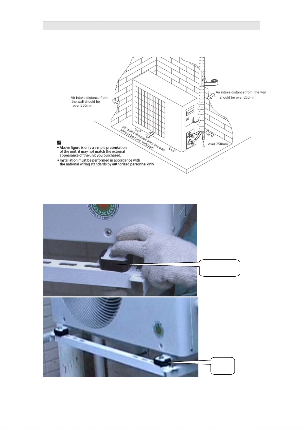
3、Outdoor Unit:
3.1. The distance of the outdoor unit:
Note: The wallboard supporting force should be able to withstand four times
the weight of the outdoor unit, and not less than 180 kg.
3.2. Fix for the outdoor unit:
Note: The outdoor unit base must be fixed with the bolts to reduce vibration
and noise, if necessary the shock pad can be used.
4. The height difference and the connection pipe length:
bolt
Shock pad
2
2.
.INSTALLATION
INSTALLATION
When install the unit, please follow the following principle:
4.1.The height difference between the indoor unit and the outdoor unit
should not exceed 5m;
4.2.The connection pipe length should be not less than 1m;
4.3.The longest connection pipe is 15m
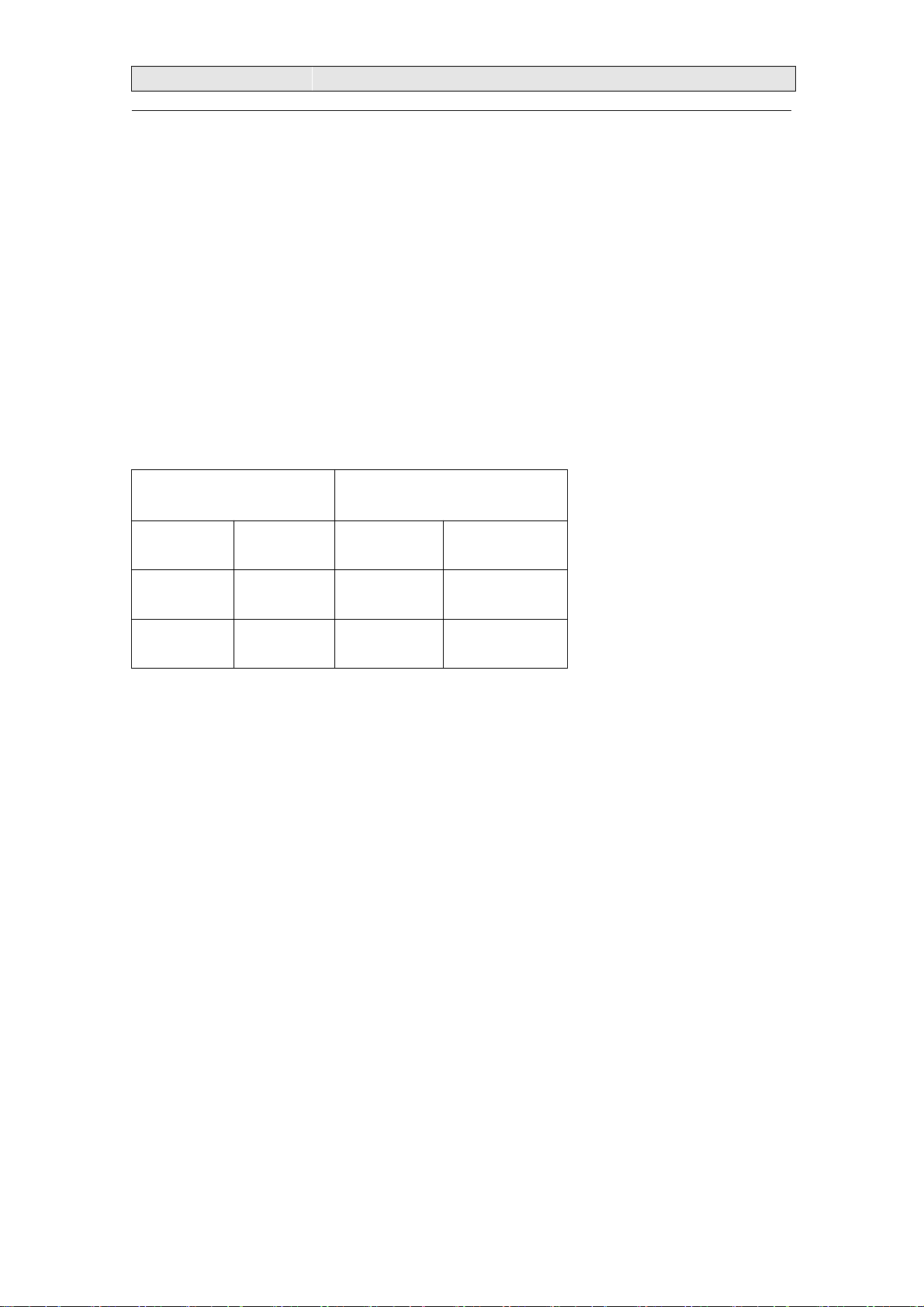
4.4. Normally, the connection pipe does not exceed 5m, if the connection
pipe exceed 5m, it should add some gas for the unit, the amount of the gas
that recharged is based on the diameter and length of the liquid pipe, and the
recharged gas Xg=(the liquid pipe length -5m)*(*sheet*g/m), for example, for
one heat pump single split air conditioner, if the diameter of the liquid pipe is
Ф9.53 , and the liquid pipe length is 7m, it means that it should charge
(7m-5m)*50g/m=100g gas for the unit refer to the following sheet:
The diameter for the
connection pipe(mm) single split air
conditioner
Liquid pipe Gas pipe cooling only
(g/m)
heat pump(g/
m)
Ф6.35 Ф9.53 or
Ф12.7 15 20
Ф6.35 or
Ф9.53
Ф15.88 or
Ф19.05 15 50
3
3.
.REFRIGERANT
REFRIGERANT FLOW
FLOW DIAGRAM
DIAGRAM
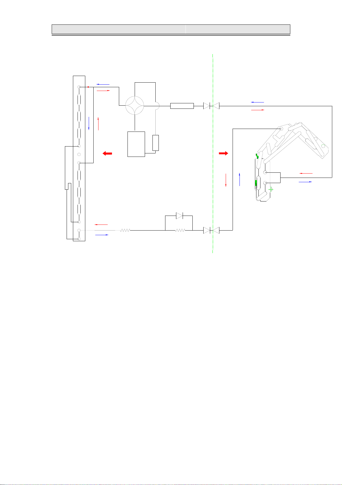
3-1. Refrigerant flow diagram :
CAPILLARY
COMPRESSOR
CHECK VALVE ASS'Y
CAPILLARY
CONDENSER
EVAPORATOR
OUTDOOR
INDOOR
出2

3
3.
.REFRIGERANT
REFRIGERANT FLOW
FLOW DIAGRAM
DIAGRAM
3-2.
4
4.
.
E
EL
LE
EC
CT
TR
RI
IC
CA
AL
L
D
DA
AT
TA
A
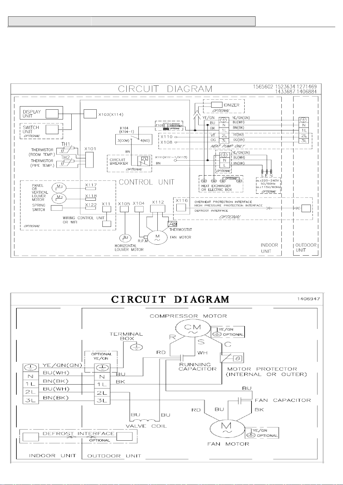
4-1.Electrical wiring diagrams
NOTE: YE/GN=YELLOW/GREEN, BU=BLUE, BN=BROWN, WH=WHITE, BK=BLACK, VT=VIOLET, OG=ORANGE,
RD=RED
INDOOR:
(1)AS-07HR4SYDDH AS-09HR4SYDDH3 AS-12HR4SVDDH1 AS-18HR4SWADH1 AS-24HR4SFADH
(INDOOR):
OUTDOOR
(1)AS-07HR4SYDDH AS-09HR4SYDDH3 AS-12HR4SVDDH1(OUTDOOR):
This manual suits for next models
4
Popular Split Type Air Conditioner manuals by other brands


Fujitsu
Fujitsu ARHC72LHTA Service manual

Mitsubishi Electric
Mitsubishi Electric PUH-P8MYA Technical & service manual

Toshiba
Toshiba RAS-10N3KV2 Series owner's manual

Mitsubishi Electric
Mitsubishi Electric MSZ-FD25VA operating instructions

Mitsubishi Electric
Mitsubishi Electric PEFY-P-VMHS-E installation manual

Toshiba
Toshiba RAS-H10S3KS-M owner's manual


