Mitsubishi Electric MSZ-FH25VE - E1 User manual
CONTENTS
1. TECHNICAL CHANGES ··································· 3
2. PART NAMES AND FUNCTIONS····················· 4
3. SPECIFICATION················································ 5
4. NOISE CRITERIA CURVE ································ 6
5. OUTLINES AND DIMENSIONS ························ 7
6. WIRING DIAGRAM············································ 8
7. REFRIGERANT SYSTEM DIAGRAM············· 10
8. SERVICE FUNCTIONS ····································11
9. MICROPROCESSOR CONTROL ··················· 13
10. TROUBLESHOOTING····································· 21
11. DISASSEMBLY INSTRUCTIONS···················· 38
SERVICE MANUAL
PARTS CATALOG (OBB623)
NOTE:
RoHS compliant products have <G> mark on the spec name plate.
Outdoor unit service manual
MUZ-FH·VEHZ Series (OBH625)
MUZ-FH·VE Series
MXZ-D·VA Series
No. OBH623
REVISED EDITION-D
Models
MSZ-FH25VE -E1 , ER1
MSZ-FH35VE -E1 , ER1
MSZ-FH50VE -E1 , ER1
MSZ-FH25VE2 -E1 , ER1
MSZ-FH35VE2 -E1 , ER1
MSZ-FH50VE2 -E1 , ER1
Outdoor unit service manual
MUZ-FH·VE Series (OBH624)
MUZ-FH·VEHZ Series (OBH625)
MXZ-D·VA Series (OBH626)
Please void OBH623 REVISED EDITION-C.
Revision D:
• MSZ-FH25VE2- E1 , ER1 , MSZ-
FH35VE2- E1 , ER1 and MSZ-
FH50VE2- E1 , ER1 have been added.
INDOOR UNIT
2
<Preparation before the repair service>
Prepare the proper tools.
Prepare the proper protectors.
Provide adequate ventilation.
After stopping the operation of the air conditioner, turn off the power-supply breaker and remove the power plug.
Discharge the capacitor before the work involving the electric parts.
<Precautions during the repair service>
Do not perform the work involving the electric parts with wet hands.
Do not pour water into the electric parts.
Do not touch the refrigerant.
Do not touch the hot or cold areas in the refrigeration cycle.
When the repair or the inspection of the circuit needs to be done without turning off the power, exercise great caution not to
touch the live parts.
Use the specified refrigerant only
Never use any refrigerant other than that specified.
Doing so may cause a burst, an explosion, or fire when the unit is being used, serviced, or disposed of.
Correct refrigerant is specified in the manuals and on the spec labels provided with our products.
We will not be held responsible for mechanical failure, system malfunction, unit breakdown or accidents caused by
failure to follow the instructions.
Revision A:
• MSZ-FH50VE- E1 has been added.
Revision B:
• MSZ-FH25VE- ER1 , MSZ-FH35VE- ER1 and MSZ-FH50VE- ER1 have been added.
Revision C:
• 5. OUTLINES AND DIMENSIONS has been modified.
(The length of the connect pipes has been modified.)
• "How to check miswiring and serial signal error" has been modified.
• Some descriptions have been modified.
Revision D:
• MSZ-FH25VE2- E1 , ER1 , MSZ-FH35VE2- E1 , ER1 and MSZ-FH50VE2- E1 , ER1 have been added.
OBH623D
3
TECHNICAL CHANGES
1
These models are compatible with the outdoor units with low standby power control.
Connecting these models to the MUZ-FH·VE(HZ)-series outdoor units enables the low standby power control. Refer to the
technical guide (OBT17) about the low standby power control.
These models may be connected to the MUZ-FH·VE(HZ) series after once connected to the MXZ series and operated, for
example because of relocation. In that case, the MUZ-FH·VE(HZ) series outdoor units will not operate without taking a step.
Follow the procedure "Deleting the memorized abnormal condition" described in 10-2.1.
MSZ-FH25VE - E1
MSZ-FH35VE - E1
MSZ-FH50VE - E1
1. New model
MSZ-FH25VE -ER1
MSZ-FH35VE -ER1
MSZ-FH50VE -ER1
1. New model
MSZ-FH25VE - E1 MSZ-FH25VE2 - E1
MSZ-FH35VE - E1 MSZ-FH35VE2 - E1
MSZ-FH50VE - E1 MSZ-FH50VE2 - E1
1. Air cleaning filter has been changed.
MSZ-FH25VE -ER1 MSZ-FH25VE2 -ER1
MSZ-FH35VE -ER1 MSZ-FH35VE2 -ER1
MSZ-FH50VE -ER1 MSZ-FH50VE2 -ER1
1. Air cleaning filter has been changed.
OBH623D
4
ACCESSORIES
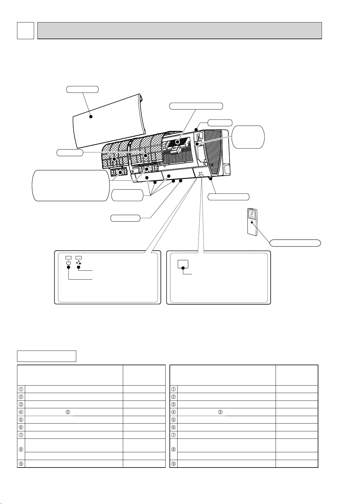
PART NAMES AND FUNCTIONS
2
Operation indicator lamp
Remote control receiving
section
Emergency
operation
switch
Horizontal
vane
Air inlet
Air ¿lter
$LUFOHDQLQJ¿OWHU
(OHFWURVWDWLFDQWLDOOHUJ\HQ]\PH¿OWHU
DQGGHRGRUL]LQJ¿OWHU06=)+9(
6LOYHULRQL]HGDLUSXULILHUILOWHUDQG
GHRGRUL]LQJILOWHU06=)+9(
)URQWSDQHO
$LURXWOHW
$LUSXULI\LQJGHYLFH
LVHH6(1625
$,5385,)<,1*
32:(5
Remote controller
MSZ-FH25VE MSZ-FH35VE MSZ-FH50VE
MSZ-FH25VE2 MSZ-FH35VE2 MSZ-FH50VE2
Model MSZ-FH25VE
MSZ-FH35VE
MSZ-FH50VE
Installation plate 1
Installation plate fixing screw 4 × 25 mm 5
Remote controller holder 1
Fixing screw for 3.5 × 16 mm (Black) 2
Battery (AAA) for remote controller 2
Wireless remote controller 1
Felt tape (For left or left-rear piping) 1
Air cleaning filter
(Electrostatic anti-allergy enzyme filter) 1
Air cleaning filter (Deodorizing filter) 1
Air purifying device 1
Model MSZ-FH25VE2
MSZ-FH35VE2
MSZ-FH50VE2
Installation plate 1
Installation plate fixing screw 4 × 25 mm 5
Remote controller holder 1
Fixing screw for 3.5 × 16 mm (Black) 2
Battery (AAA) for remote controller 2
Wireless remote controller 1
Felt tape (For left or left-rear piping) 1
Air cleaning filter
(Silver-ionized air purifier filter) 1
Air cleaning filter (Deodorizing filter) 1
Air purifying device 1
OBH623D

5
Indoor model
MSZ-FH25VE
MSZ-FH25VE2
MSZ-FH35VE
MSZ-FH35VE2
MSZ-FH50VE
MSZ-FH50VE2
Power supply Single phase 230 V, 50 Hz
Electrical
data
Power input 1 Cooling W29 31
Heating 29 31
Running current
1Cooling A0.28 0.29
Heating 0.28 0.29
Fan
motor
Model RC0J30-MD
Current 1Cooling A0.28 0.29
Heating 0.28 0.29
Dimensions W × H × D mm 925 × 305(+17) × 234
Weight kg 13.5
Special remarks
Air direction 5
Airflow
Cooling
Super High
m3/h
696 744
High 516 606
Med. 378 516
Low 282 444
Silent 234 384
Heating
Super High
m3/h
792 876
High 552 672
Med. 384 540
Low 282 432
Silent 240 342
Sound level
Cooling
Super High
dB(A)
42 44
High 36 39
Med. 29 35
Low 23 24 31
Silent 20 21 27
Heating
Super High
dB(A)
44 46
High 36 39
Med. 29 34
Low 24 29
Silent 20 21 25
Fan speed
Cooling
Super High
rpm
1,220 1,280
High 970 1,090
Med. 770 970
Low 630 870
Silent 550 780
Heating
Super High
rpm
1,350 1,460
High 1,020 1,180
Med. 780 1,000
Low 630 850
Silent 560 720
Fan speed regulator 5
Remote controller model SG13A SG15C SG13A SG15C SG13A SG15C
NOTE: Test conditions are based on ISO 5151.
Cooling: Indoor Dry-bulb temperature 27°C Wet-bulb temperature 19°C
Outdoor Dry-bulb temperature 35°C
Heating: Indoor Dry-bulb temperature 20°C
Outdoor Dry-bulb temperature 7°C Wet-bulb temperature 6°C
1 Measured under rated operating frequency.
SPECIFICATION
3
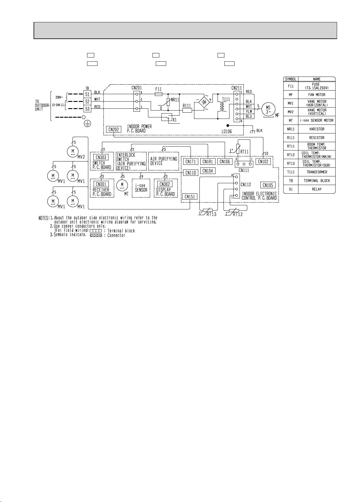
Specifications and rating conditions of main electric parts
Fuse (F11) T3.15AL250V
Horizontal vane motor (MV1) 12 VDC
Vertical vane motor (MV2) 12 VDC
i-see SENSOR MOTOR (MT) 12 VDC
Varistor (NR11) S10K300E2K1
Terminal block (TB) 3P
OBH623D
6
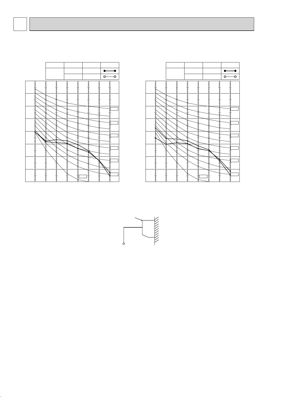
90
80
70
60
50
40
30
20
10 63 125 250 500 1000 2000 4000 8000
NC-60
NC-50
NC-40
NC-30
NC-20
NC-70
OCTAVE BAND SOUND PRESSURE LEVEL, dB re 0.0002 MICRO BAR
BAND CENTER FREQUENCIES, Hz
COOLING
FUNCTION SPL(dB(A)) LINE
Super High
FAN SPEED
HEATING
42
44
NC-10
NOISE CRITERIA CURVE
4
Test conditions
Cooling: Dry-bulb temperature 27 °C
Wet-bulb temperature 19 °C
Heating: Dry-bulb temperature 20 °C
INDOOR UNIT WALL
MICROPHONE
0.8m
1m
90
80
70
60
50
40
30
20
10 63 125 250 500 1000 2000 4000 8000
NC-60
NC-50
NC-40
NC-30
NC-20
NC-70
OCTAVE BAND SOUND PRESSURE LEVEL, dB re 0.0002 MICRO BAR
BAND CENTER FREQUENCIES, Hz
COOLING
FUNCTION SPL(dB(A)) LINE
Super High
FAN SPEED
HEATING
44
46
NC-10
MSZ-FH25VE MSZ-FH35VE
MSZ-FH25VE2 MSZ-FH35VE2 MSZ-FH50VE
MSZ-FH50VE2
OBH623D
7
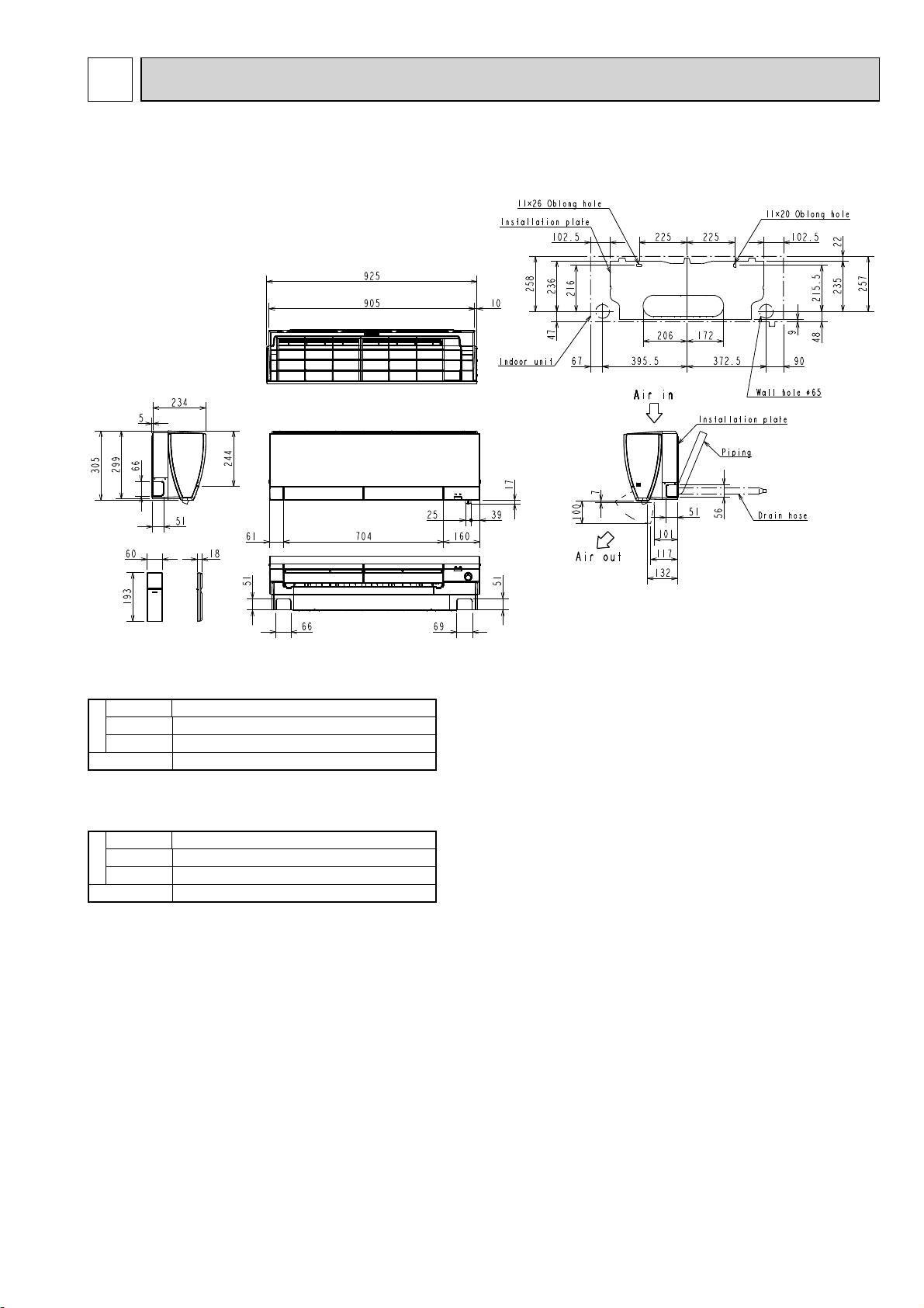
Unit: mm
MSZ-FH25VE MSZ-FH35VE
MSZ-FH25VE2 MSZ-FH35VE2
Piping
Insulation ø37 O.D
Liquid line ø6.35 - 0.50 m (Flared connection ø6.35)
Gas line ø9.52 - 0.43 m (Flared connection ø9.52)
Drain hose Insulation ø28 O.D Connected part ø16 O.D
OUTLINES AND DIMENSIONS
5
MSZ-FH50VE
MSZ-FH50VE2
Piping
Insulation ø37 O.D
Liquid line ø6.35 - 0.50 m (Flared connection ø6.35)
Gas line ø9.52 - 0.43 m (Flared connection ø12.7)
Drain hose Insulation ø28 O.D Connected part ø16 O.D
MSZ-FH25VE MSZ-FH35VE MSZ-FH50VE
MSZ-FH25VE2 MSZ-FH35VE2 MSZ-FH50VE2
OBH623D
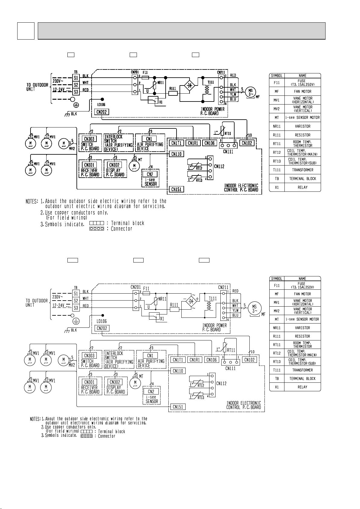
8
MSZ-FH25VE - E1 MSZ-FH35VE - E1 MSZ-FH50VE - E1
WIRING DIAGRAM
6
MSZ-FH25VE - ER1 MSZ-FH35VE - ER1 MSZ-FH50VE - ER1
OBH623D
9
MSZ-FH25VE2 - E1 MSZ-FH35VE2 - E1 MSZ-FH50VE2 - E1
MSZ-FH25VE2 - ER1 MSZ-FH35VE2 - ER1 MSZ-FH50VE2 - ER1
OBH623D

10
Indoor
heat
exchanger
Flared connection
Room temperature
thermistor
RT11
Flared connection
Refrigerant pipe ø9.52
(with heat insulator)
Refrigerant pipe ø6.35
(with heat insulator)
Indoor coil
thermistor
RT12 (main)
Indoor coil
thermistor
RT13 (sub)
Refrigerant flow in cooling
Refrigerant flow in heating
Unit: mm
REFRIGERANT SYSTEM DIAGRAM
7
Indoor
heat
exchanger
Flared connection
Room temperature
thermistor
RT11
Flared connection
Refrigerant pipe ø12.7
(with heat insulator)
Refrigerant pipe ø6.35
(with heat insulator)
Indoor coil
thermistor
RT12 (main)
Indoor coil
thermistor
RT13 (sub)
Refrigerant flow in cooling
Refrigerant flow in heating
MSZ-FH25VE MSZ-FH35VE
MSZ-FH25VE2 MSZ-FH35VE2
MSZ-FH50VE
MSZ-FH50VE2
OBH623D
Other manuals for MSZ-FH25VE - E1
1
This manual suits for next models
13
Table of contents
Other Mitsubishi Electric Split Type Air Conditioner manuals

Mitsubishi Electric
Mitsubishi Electric MSZ-FD25VA User manual

Mitsubishi Electric
Mitsubishi Electric PUZ-ZM100VKA User manual

Mitsubishi Electric
Mitsubishi Electric PUH-P8MYA Operating manual

Mitsubishi Electric
Mitsubishi Electric PEFY-P-VMHS-E User manual

Mitsubishi Electric
Mitsubishi Electric MSZ-GB50VA Series User manual


