2Your company internal use only.Copyright (C) Mitsubishi Electric Corporation.
NR-242UM-13LND0,13-WS
FEATURES
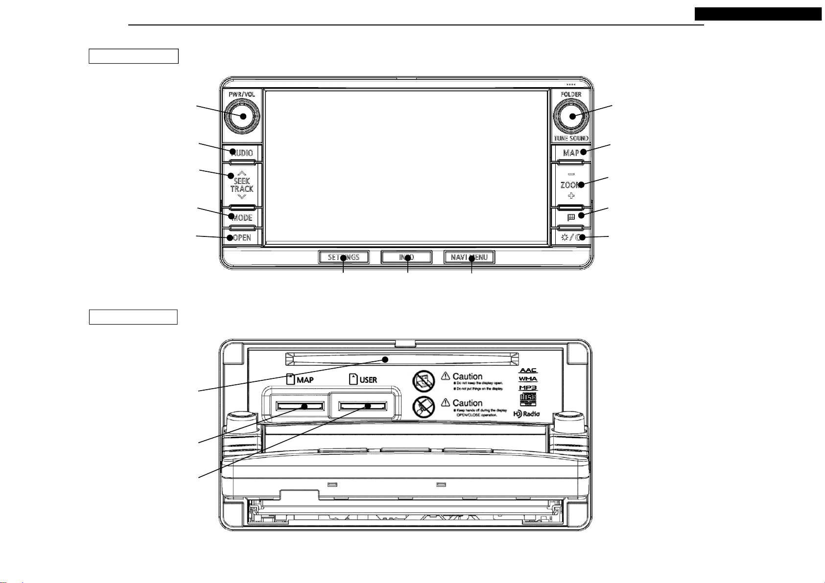
< Display Part >
●Panel design : Wide 2DIN size
●Button illumination : Umber
●LCD : 6.95inch WVGA
●Touch panel : Resistive type (Glass-Glass, Retardation film)
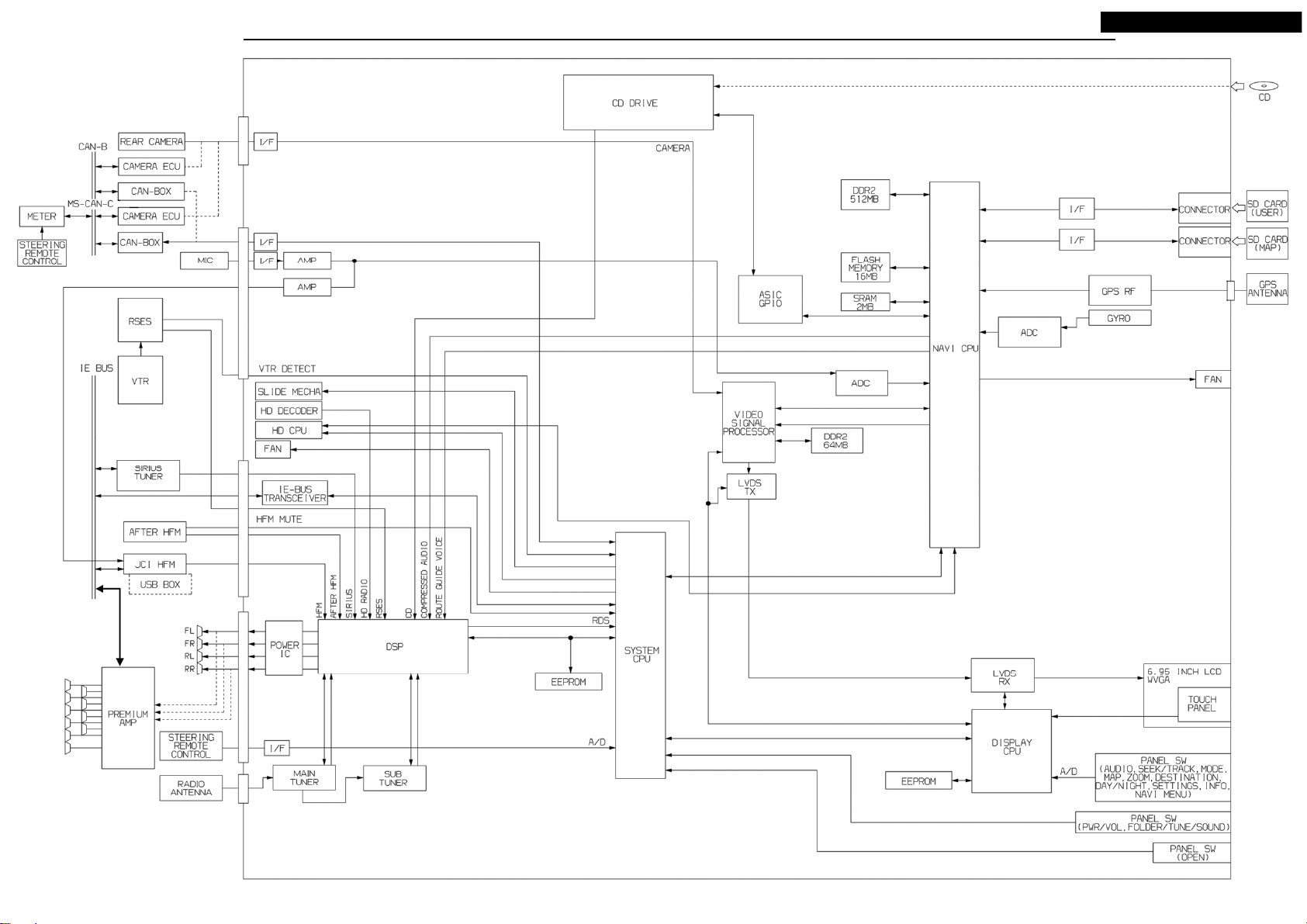
●Display U-com : M16C
< Navigation Part >
●Navi U-com : NaviJ3 (Working frequency : 533MHz)
●Work / Program memory
: DDR2-SDRAM 512MB
●Boot memory : Flash memory 16MB
●Back up memory : SRAM 2MB
●SD card (MAP data)
: Panasonic RP-SDP16G Series (16GB)
●GPS receiver : Built-in GPS-IP
●Gyro sensor : MEMS Gyro (Murata manufacturing)
●Voice recognition function
< Audio Part >
●Audio U-com : V850ES / SJ3
●DSP : SAF7741HV / N125 (DiRaNa2)
●Radio tuner : TEF7000HV / V3 (LeafDice x2)
●RBDS
●Traffic Information : NAVTEQ Traffic RDS
: HD-Traffic
●HD Radio : SAF3560HV / V1102 HD1.5 (Cayman)
●CD drive : Mitsubishi 8th CD mecha (8cm disc not supported)
(Supported Media : CD, CD-R, CD-RW)
(Supported Format : CD-DA, CD-ROM)
(Supported File : MP3, WMA, AAC)
●SD card (USER) : (Supported Media : SD, SDHC)
(Supported File : MP3, WMA, AAC, WAV)
●USB Audio play : via JCI external hands free module, or via Mitsubishi USB-BOX
●iPod Audio play : via JCI external hands free module, or via Mitsubishi USB-BOX
●Bluetooth Audio play
: via JCI external hands free module
< External Connect Part >
●Steering switch
●Cell phone : via JCI external hands free module
●iPod : via JCI external hands free module, or via Mitsubishi USB-BOX
●USB memory : via JCI external hands free module, or via Mitsubishi USB-BOX
●Rear camera
●Camera ECU connector (OUTLANDER and OUTLANDER PHEV)
: via outside CAN-BOX (MS-CAN-C)
Camera ECU connector (OUTLANDER SPORT, LANCER and LANCER SPORT BACK)
: via outside CAN-BOX (CAN-B)
●Premium amp : CV-0MW3R45-2, CV-0MW3R45-4, CV-0MW3R45-5,
CV-0MW3B45
●RSES : Built-in DISC drive
●VTR : via RSES
●Sirius tuner : CQ-0MU3IEB, CQ-0MU3IEB-C
●Hands free module
: JCI external hands free module,
For after JCI external hands free module
●USB-BOX : Mitsubishi