
ALTERNATIVE METHOD OF CODE READING
DISCLAIMER: DO NOT ATTEMPT ANY WIRING MODIFICATIONS YOURSELF WITHOUT (A)
CHECKING THE CONNECTIONS, WIRE COLOURS, ETC. ON YOUR OWN VEHICLE, AND (B)
KNOWING WHAT YOU ARE DOING. I TAKE NO RESPONSIBILITY FOR ANY COOKED WIRING,
ECUS OR ANYTHING ELSE YOU MAY FEEL LIKE PLAYING WITH. ANY WORK DONE ON YOUR
OWN VEHICLE IS DONE SO AT YOUR OWN RISK...
The first step is to remove the panel underneath
the steering wheel. This simply requires the
removal of four screws. Note that the bonnet
release cable and lever will still be connected to
this panel - just drop the panel down and keep it
out of the way.
Now if you crawl under there, you will notice an
interface socket on the left hand side, about level
with the bottom left screw you removed a moment
ago. You can click on the image (right) to
enlarge...
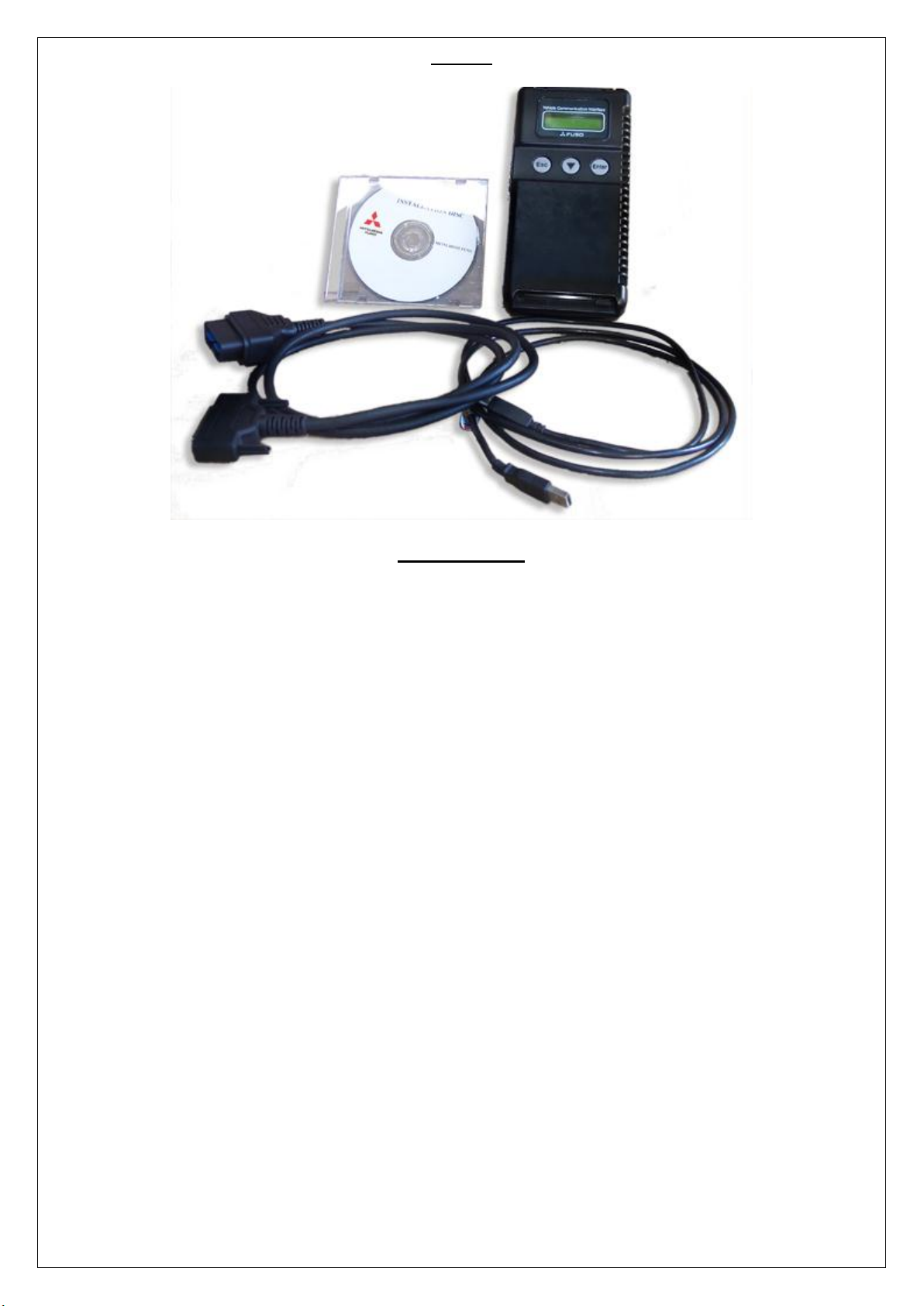
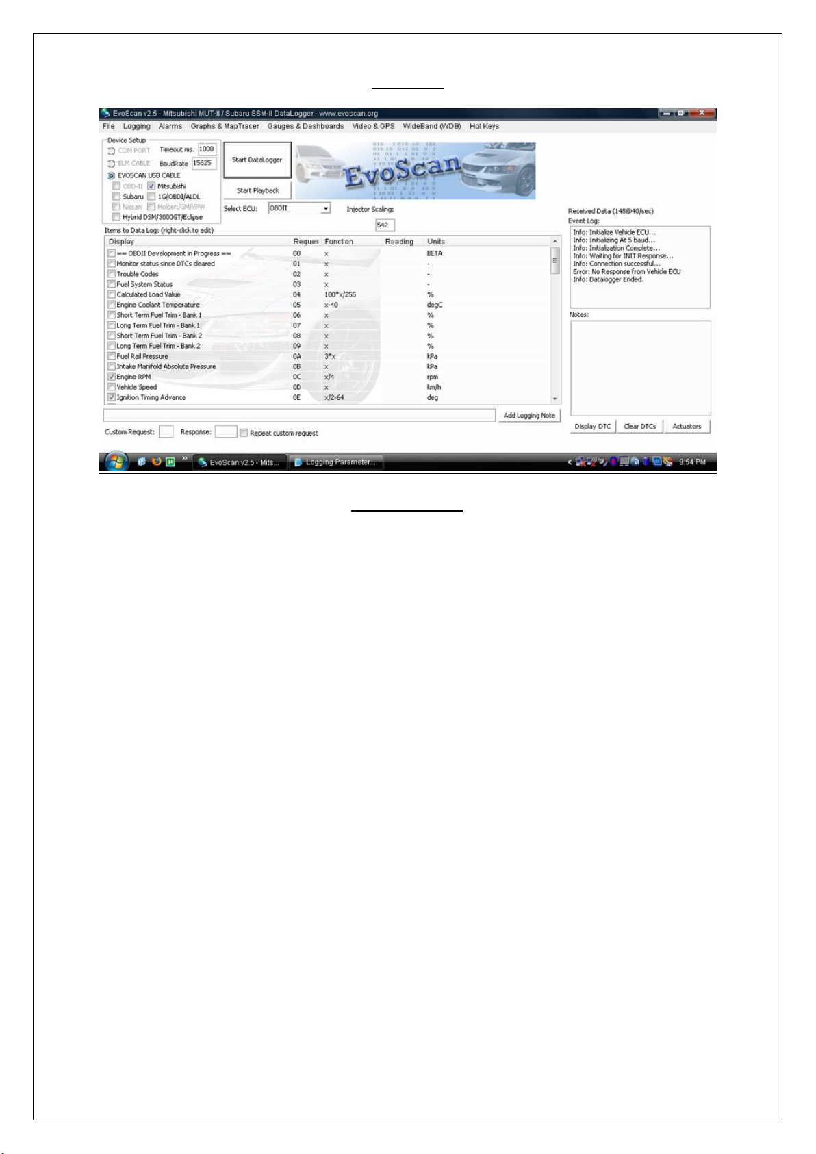
This is the location of the diagnosis connector and
where a MUT-II, MUT-III or EVO SCAN unit can be
connected.
STEP 1
Earth No. 1 terminal (diagnostic control terminal) of the diagnostic connector.
STEP 2
Turn on the ignition switch.
The picture is oriented to the rear of the
vehicle. the strange circular thing in the centre
of the frame is simply the alarm's glass
breakage sensor.
As noted before, we must earth No. 1
terminal on this connector. The pin in
question is the bottom right one in the picture
- highlighted.
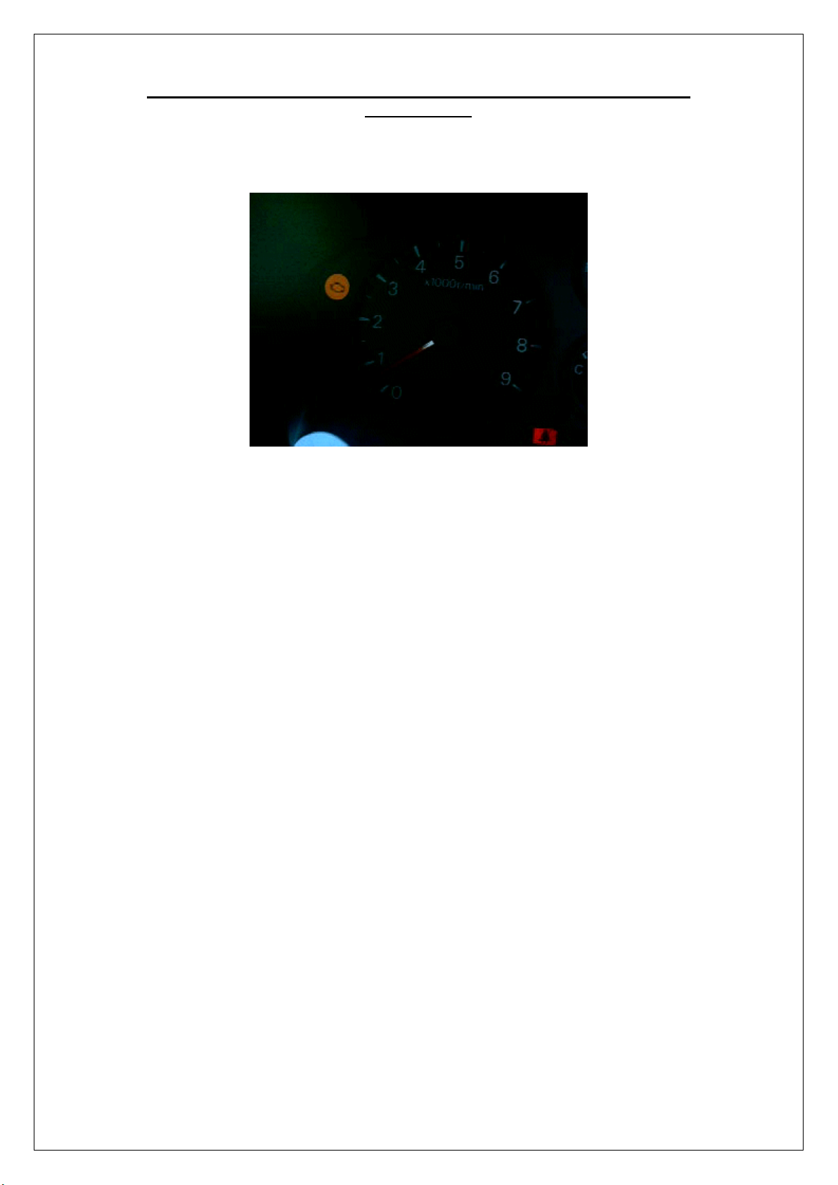
All we have to do is ground out this pin by
using a single cable. With the engine ignition
switch on, the computer will flash the engine
warning light to indicate any stored diagnostic
code(s).
At the back of the diagnostic plug, it was clear
to see that the relevant pin was connected to
an easily accessible lead (grey with red stripe)
on this 1995 GPX, but can be a different
colour on some other FTOs.
a standard patch connector was used to
attach an extra wire to the relevant lead (see
image to right, highlighted).
Now it is simply a matter of grounding out the
permanent diagnostic lead stowed under the
dash.


