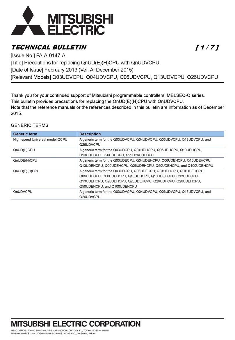
Mitsubishi Q00JCPU User manual

1System Structure
2Supported Device Addresses
3Consecutive Device Addresses
4Environment Setup
5I/O Manager Configuration
6Driver Configuration
7Protocol Configuration
8Device Address Configuration
Mitsubishi Electric
Melsec-Q
Ethernet (UDP) Driver
• This manual explains how to connect the target machine with other manufacturer devices. For
information about how to use the Pro-Designer software, please refer to the Pro-Designer Online
Help.
• The types of target machines that are compatible with Pro-Designer depends on the version of
Pro-Designer. For information about the compatibility of target machines, please refer to the
Pro-Designer Online Help.
© 2002 Digital Electronics Corporation. All rights reserved.

2
Mitsubishi Electric Melsec-Q Ethernet (UDP) Driver
1 System Structure
The following table describes the basic system setup for connecting targets machine to Mitsubishi
Melsec-Q Series PLCs.
Series CPU EthernetModule
MELSEC-Q Series
Q00CPU
Q00JCPU
Q01CPU
Q02CPU
Q02HCPU
Q06HCPU
Q12HCPU
Q25HCPU
QJ71E71
QJ71E71-B2
Use a 10BASE-T connection for PS Series Type G, PS Series Type P,
and GP2000 Series target machines.

3
Mitsubishi Electric Melsec-Q Ethernet (UDP) Driver
2 Supported Device Addresses
The following table lists the device address ranges you can enter from the Device Address
keypad. For actual device address ranges supported by the PLC, refer to the corresponding PLC
manual
Supported device addresses differ from protocol to protocol and between PLC models.
Device BitAddress Word Address 16 bit 32 bit
Input Relay X0000-XFFFF X0000-XFFF0*1
Output Relay Y0000-YFFFF Y0000-YFFF0*1
Internal Relay M00000-M65535 M00000-M65520*2
Latch Relay L00000-L65535 L00000-L65520*2
Special Relay SM0000-SM9999 SM0000-SM9984*2
Annunciator F00000-F65535 F00000-F65520*2
Edge Relay V00000-V65535 V00000-V65520*2
Step Relay S0000-S9999 S0000-S9984*2
Link Relay B0000-BFFFF B0000-BFFF0*1
Special Link Relay SB000-SBFFF SB000-SBFF0*1
Timer (contact) TS00000-TS65535 --
Timer (coil) TC00000-TC65535 --
Retentive Timer (contact) SS00000-SS65535 --
Retentive Timer (coil) SC00000-SC65535 --
Counter (contact) CS00000-CS65535 --
Counter (coil) CC00000-CC65535 --
Timer (current value) -- TN00000-TN65535
Retentive Timer (current value) -- SN00000-SN65535
Counter (current value) -- CN00000-CN65535
Data Register*3 D00000:0-D65535:15 D00000-D65535*4
Special Register*3 SD0000:0-SD9999:15 SD0000-SD9999*4
Link Register*3 W0000:0-WFFFF:F W0000-WFFFF*5
Special Link Register*3 SW000:0-SWFFF:F SW000-SWFFF*5
File Register(Normal)*3 R00000:0-R65535:15 R00000-R65535*4
0R0000:0-0R7FFF:F 0R0000-0R7FFF*5
1R0000:0-1R7FFF:F 1R0000-1R7FFF*5
2R0000:0-2R7FFF:F 2R0000-2R7FFF*5
... ...
30R0000:0-30R7FFF:F 30R0000-30R7FFF*5
31R0000:0-31R7FFF:F 31R0000-31R7FFF*5
L/H*6 L/H*6
File Register(0R-31R)*3
*1 To use as word address, the bit number (last digit) must be 0.
*2 To use as word address, must be multiple of 16.
*3 When the bit write operation is performed, the Target Machine reads the PLC’s
corresponding word address and turns a bit ON, then send back to PLC. Do not write to the
word address from the ladder program in the middle of this operation.
*4 You can define a bit address by adding a colon followed by the bit position (0~15) at the end
of the word. (e.g. D0000:15)
*5 You can define a bit address by adding a colon followed by the bit position (0~F) at the end
of the word. (e.g. W0000:F)

4
Mitsubishi Electric Melsec-Q Ethernet (UDP) Driver
*6 16-bit and 32-bit data, High and Low, refer to data as defined in the following examples.
Byte Word
07. . . 0L(Low) 015 . . . 0L(Low)
115 . . . 8H(High) 131 . . . 16 H (High)
16 bit 32 bit

5
Mitsubishi Electric Melsec-Q Ethernet (UDP) Driver
3 Consecutive Device Addresses
The following table lists the maximum number of consecutive addresses and the gap span (the
maximum gap span between PLC device addresses that are used as consecutive device addresses)
that be read by each PLC. Refer to these tables to utilize Block Transfer.
•To speed up data communication, use consecutive device addresses on
the same panel screen.
•The following situations increase the number of times that the device is
read, and reduces the data communication speed between the target
machine and the PLC:
•when the number of consecutive addresses exceeds the maximum
•when an address is designated for division
•when different device types are used
Device Max.Consecutive
Addresses Gap Span
Input Relay(X)
Output Relay(Y)
Internal Relay (M)
Latch Relay(L)
Link Relay(B)
Timer [contact] (TS)
Timer [coil] (TC)
Counter [contact](CS)
Counter [coil] (CC)
Data Register (D)
Link Register (W)
File Register (R)
Extended File Register(R)
Timer [current value] (TN)
Counter [current value] (CN)
2000 bits 47 bits
480 words 48 words

6
Mitsubishi Electric Melsec-Q Ethernet (UDP) Driver
4 Environment Setup
Prior to the target machine starting communciation with a Melsec-Q PLC, the MNET/10H
Ethernet settings must be set in the PLC's ladder logic software. The setting values are as shown
below.
1. Network Parameter MNET/10H Ethernet Settings
2. Ethernet Operation Settings
3. OPEN Settings
1. Network Parameter MNET/10H Ethernet Settings
Items PLC Settings
Network Classification Ethernet
First I/O No. Anynumber *1
Network No. Anynumber *1
Group No. Anynumber *1
Machine No. Anynumber *1
Mode Online
*1 This setting does not effect the communication with the target machine.
2. Ethernet Operation Settings
Items PLC Settings
Data Code Settings BINARYCode
Initial Timing Settings Always waiting forOPEN
IP Address Settings Anynumber
Write Possible in RUN
mode*1 Anynumber
*1 When performing Write from the target machine in RUN mode, set the Write Possible in
RUN mode to "Allowed".
Be sure to make sure the IP address to your network administrator.
Do not specify the duplicate IP address.

7
Mitsubishi Electric Melsec-Q Ethernet (UDP) Driver
3. OPEN Settings
Items PLC Settings
Protocol UDP/IP
SRC Port No. Should be the same DEST PortNo.
as setin the [Protocol Configuration]
dialogbox.
DEST IP Address Should be the same IP Address as
the target machine's.
DEST Port Address Should be the same UDP Port No.
as set in the [Driver Configuration]
dialogbox.
Fixed Buffer Anynumber *1
Fixed Buffer Method Anynumber *1
Paring Open Anynumber *1
Confirming Anynumber *1
*1 This setting does not effect the communication with the target machine.
Be sure to make sure the IP address to your network administrator.
Do not specify the duplicate IP address.
When the Auto Open UDP Port feature is used, the Table 3. OPEN Settings are not needed.
When these settings are used, however, the PLC's port number is 5000 (default setting).
For details, refer to Mitsubishi Electric's Q and QnA Series Ethernet Interface User Manuals.

8
Mitsubishi Electric Melsec-Q Ethernet (UDP) Driver
5 I/O Manager Configuration
The driver and protocol, which enable communication between the target machine and the PLC,
depends on the PLC type.
For information on how to display the [New Driver Interface] dialog box,
see the online help.

9
Mitsubishi Electric Melsec-Q Ethernet (UDP) Driver
6 Driver Configuration
Use the [Driver Configuration] dialog box to define communication settings on the target
machine.
For information on how to display the [Driver Configuration] dialog box,
see the online help.
Command Time Interval
Not applicable.
Timeout
Defines the length of time the target machine waits for a communication packet before it retries
communication or outputs an error. (1-180)
UDP Retry Count
Defines the number of times the target machine resends a packet before it outputs an error. (0-
255)
UDP Port No.
Enter a value to identify on the target machine, the port number used for UDP communication.
(1024-65535)

10
Mitsubishi Electric Melsec-Q Ethernet (UDP) Driver
7 Protocol Configuration
To set up details about the communication process between the target machine and the PLC, use
the [Protocol Configuration] dialog box.
For information on how to display the [Protocol Configuration] dialog box,
see the online help.
Destination IP Address
Specifies the Destination IP address (PLC), devided 32 bits into 4 parts, each part is consisted of
8 bits and devided by dots. Enter an integer value between 0 and 255, both inclusive.
Be sure to make sure the IP address to your network administrator.
Do not specify the duplicate IP address.
Destination Port No.
Enter a value (1024-65535) to match the PLC’s Ethernet port number.
Port No. 5001 and 5002 are not available. They are used only for the ethernet unit system and the
PLC's ladder logic software. When using the Auto Open UDP Port feature, enter 5000 (defaut
setting value) for the Port No.
Network No.
Designates the network number when communicating via the network. Specify an integer value
between 1 and 239, both inclusive, or 254, to identify the communicating PLC. If not
communicating via the network, enter 0.
PLC No.
Designates the PLC number when communicating via the network. Specify an integer value
between 0 and 64, both inclusive to identify the communicating PLC. If not communicating via
the network, enter 255.

11
Mitsubishi Electric Melsec-Q Ethernet (UDP) Driver
8 Device Address Configuration
To set up a PLC variable in the Variable List, use the Device Address Keypad from the variable
properties.
See Section 3 – Supported Device Addresses.
For information on how to display the Device Address Keypad, see the
online help.
Device
Lists the PLC’s discrete and word device types.
Address
Enter the device address for the PLC variable. The keypad ensures that you enter the correct
format for bit and word devices.
Other manuals for Q00JCPU
2
This manual suits for next models
7
Table of contents
Other Mitsubishi Microcontroller manuals