Page Number - 2 Form 822964
Important Precautions
· Brake fluid is highly corrosive.
Wear gloves and approved safety
goggles at all times, and prevent
contact of the fluid with painted
surfaces.
· Consult and follow the vehicle
manufacturer’s recommended
procedures when servicing any
hydraulic system.
· Properly dispose of old fluids, and
replenish hydraulic systems with
new brake fluid from freshly opened
containers.
Principle of Operation
This unit is designed to automatically
maintain the level of new brake fluid
in the master or slave cylinder of a hy-
draulic brake or clutch system while the
system is bled manually or by vacuum.
Fluid flows from a reservoir into the
master cylinder by means of a tube and
base. The unit has a ¼ turn valve for
turning the flow on or off, and means
for adjusting the level of fluid in the
master cylinder. A 1200 ml reservoir is
included for use when dispensing fluids
from bulk containers.
Instructions for use
Important: This unit is designed for
servicing a variety of vehicles in a
safe, convenient manner. However,
the varying shapes, sizes, designs and
locations of master cylinders prevent its
use on every vehicle and application.
Check the unique design and location
of your master cylinder prior to proceed-
ing with the following instructions.
Gravity Feed
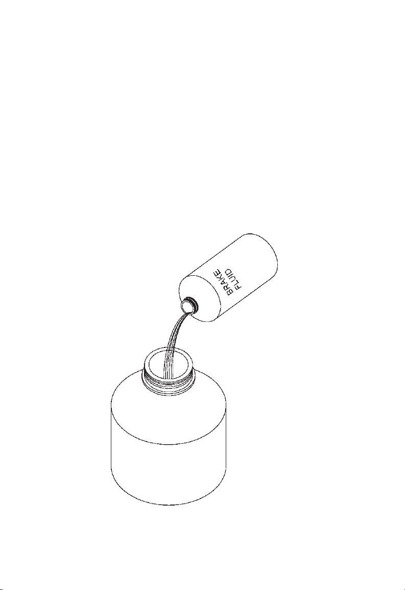
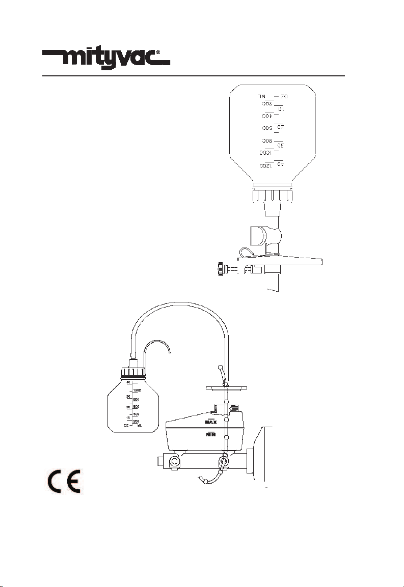
1. Fill the 1200 ml reservoir with ve-
hicle manufacturer’s recommended
brake fluid, to a level exceeding the
amount of fluid to be bled (Fig 1),
and install the lid.
2. Clean the exterior of the master
cylinder and master cylinder cap
to prevent dirt from entering the
master cylinder when the cap is
removed.
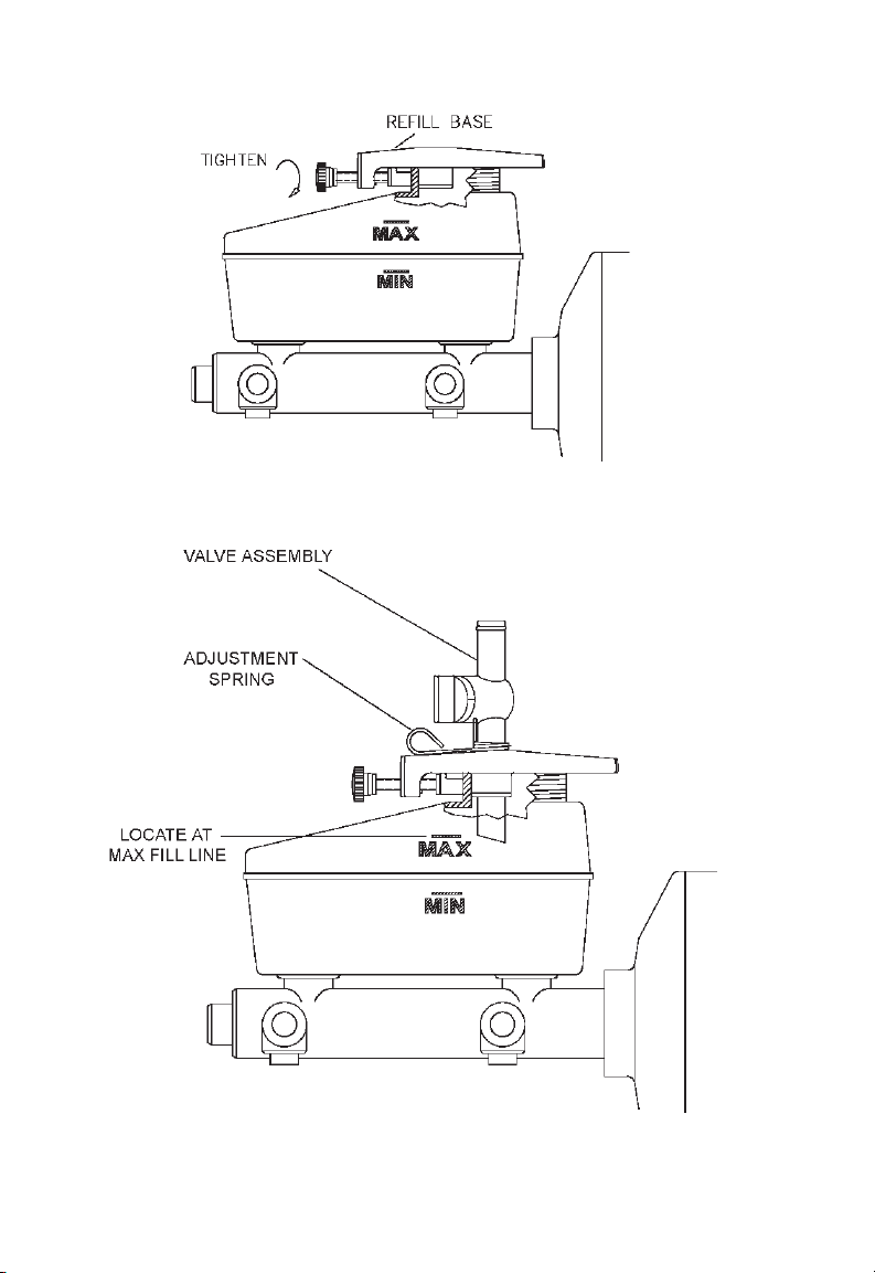
3. Remove the cap from the master
cylinder, and set the Refill Base
onto the neck of the master cylinder.
4. Clamp the base to the neck of the
master cylinder by tightening the
Sliding Block Knob (Fig 2).
5. Install the Adjustment Spring onto
the neck of the Valve Assembly as
shown (Fig 3).
6. Slide the neck of the Valve As-
sembly through the hole in the
Refill Base, and use the Adjustment
Spring to align the bottom of the
neck with the MAX fill line on the
master cylinder (Fig 3).
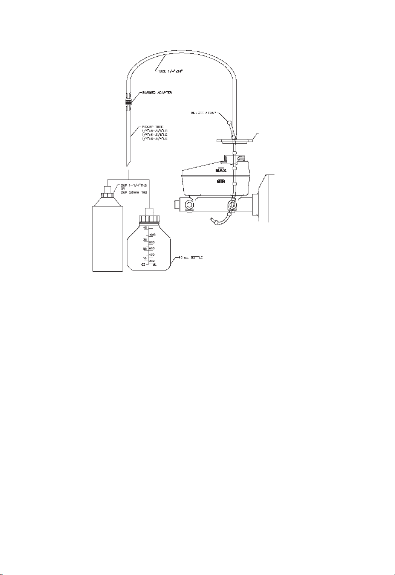
7. Remove the Valve Assembly from
the base and insert it into the lid of
the pre-filled Reservoir Bottle (Fig
4).
8. CHECK TO ENSURE THAT THE
VALVE IS IN THE “CLOSED” POSI-
TION.
9. Turn over the reservoir and valve
assembly, and insert it back into the
Refill Base (Fig 5).
10. Open the valve to allow fluid to flow
into the master cylinder. Leave
the valve open while bleeding the
hydraulic system, and the unit will
automatically maintain the level of
fluid at the MAX fill line.