Miyachi IPB-5000A-00-00 User manual

00-00
00-01
INVERTER-TYPE WELDING POWER SUPPLY
IPB-5000A-
OPERATION MANUAL
Thank you for purchasing the Miyachi Technos Inverter-type Welding Power Supply
IPB-5000A.
・For correct use, read this operation manual carefully.
・After reading, save it in a proper place where you can easily access to.
I07M0756E-01
POWERSTART
IPB-5000A
CURSOR
WELD MENU RESET
ENTER
+-
WELDING POWER SUPPLY

IPB-5000A
1
Table of Contents
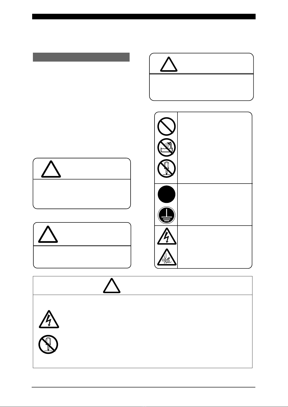
1. Special Precautions ·········································································································1-1
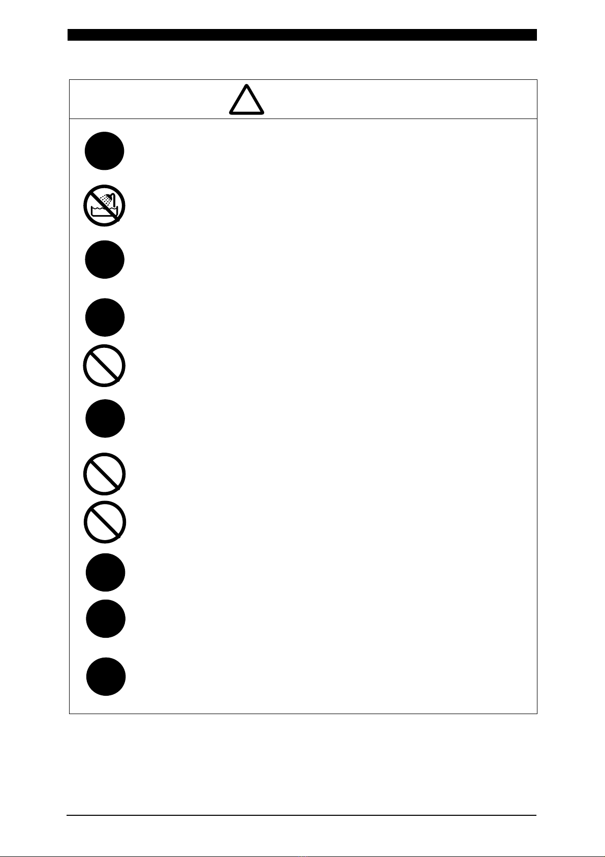
(1) Safety Precautions·······································································································1-1
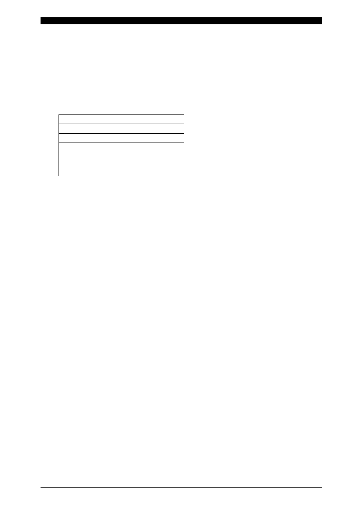
(2) Precautions for Handling······························································································1-4
(3) Warning Labels for Safety···························································································· 1-5
2. Features ····························································································································2-1
3. Packaging ·························································································································3-1
4. Name and Functions of Each Section············································································4-1
(1) Front Panel ··················································································································4-1
(2) Rear Panel ···················································································································4-3
5. Installation and Connection ····························································································5-1
(1) Installation····················································································································5-1
(2) Connection···················································································································5-2
6. Description of Display Screens ······················································································6-1
(1) Operation Flow·············································································································6-1
(2) MENU Screen ··············································································································6-2
(3) SCHEDULE Screen ·····································································································6-2
(4) MONITOR Screen········································································································6-5
(5) COMPARATOR Screen ······························································································· 6-7
(6) ENVELOPE Screen ·····································································································6-8
(7) PRECHECK Screen·····································································································6-12
(8) STATUS Screen ·········································································································· 6-13
①STATUS (1/2) Screen ·····························································································6-13
②STATUS (2/2) Screen ·····························································································6-14
③ERROR SETTING Screen ······················································································6-16
④MISC Screen ··········································································································· 6-16
7. Basic Operation················································································································7-1
8. External Interface ·············································································································8-1
(1) Connection Diagram for External Input/Output Signals ···············································8-1
①When contacts on PLC are used as input signal ····················································8-1
②When NPN transistor (sink type) on PLC is used as input signal ··························· 8-2
③When PNP transistor (source type) on PLC is used as input signal ·······················8-3
④When solenoid valves are activated by the use of an external power supply·········8-4
⑤When solenoid valves are activated by the use of an internal power supply··········8-4
(2) External Input/Output Signals ······················································································8-4
(3) Schedule No. and Schedule Select Terminals····························································· 8-8

IPB-5000A
2
Table of Contents (Continued)
9. Time Chart·························································································································9-1
(1) Fundamental Sequence·······························································································9-1
(2) Determination of Weld Schedule ·················································································9-2
(3) Behavior of START SIG. HOLD ·················································································· 9-3
(4) Behavior of END SIG. TIME ························································································9-4
(5) Behavior of SOL1 and SOL2 ·······················································································9-5
(6) “Error” or “Caution” in PRECHECK··············································································9-6
(7) At Occurrence of “Error” or “Caution”···········································································9-7
10. Specifications ·················································································································10-1
(1) Specifications ···············································································································10-1
(2) Optional Items (Separately Sold) ················································································· 10-3
①Input Cables PK-01855-□□□···············································································10-3
②Output Cables PK-01856-□□□ ············································································10-4
③[SENS] Cables SK-05741 ·······················································································10-4
11. Error Codes·····················································································································11-1
12. Outline Drawing··············································································································12-1
13. Schedule Data Table ······································································································13-1
(1) Weld Schedule Setting·································································································13-1
(2) PRECHECK Setting·····································································································13-8
(3) Monitor Setting·············································································································13-11
(4) Status Setting···············································································································13-18

IPB-5000A
1. Special Precautions
1-1
Denotes operations and practices that
may result in personal injury or damage
to the equipment if not correctly followed.
1. Special Precautions
(1) Safety Precautions
Before using, read "Safety precautions"
carefully to understand the correct
method of use.
• These precautions are shown for safe
use of our products and for prevention
of damage or injury to operators or
others. Be sure to read each of
them, since all of them are important
for safe operation.
• The meaning of the words and
symbols is as follows.
Do not touch the inside of the Power Supply unnecessarily.
Since very high voltages are charged to the inside of this Power Supply, it is
very dangerous to touch it unnecessarily.
Any person other than service personnel, or authorized representatives’
personnel must not touch the inside.
Never disassemble, repair or modify the Power Supply.
These actions can cause electric shock and fire.
If any part needs to be checked or repaired, contact Miyachi Technos Corp.
or your distributor for help.
Denotes operations and practices
that may imminently result in serious
injury or loss of life if not correctly
followed.
DANGER
!
Denotes operations and practices
that may result in serious injury o
r
loss of life if not correctly followed.
WARNING
!
These symbols denote
"prohibition". They are
warnings about actions out
of the scope of the warranty
of the product.
These symbols denote
actions which operators
must take.
Each symbol with a triangle
denotes that the content
gives DANGER, WARNING
or CAUTION to the operator.
!
DANGER
!
C
A
UTION
!

IPB-5000A
1. Special Precautions
1-2
Do not put your hands between the electrodes.
When welding, keep your fingers and hands away from the electrodes.
Do not touch any welded part or electrodes during welding and just after
welding finished.
The welded part of a workpiece, electrodes and arm are very hot.
Do not touch them; otherwise you may be burnt.
Ground the equipment.
If the Power Supply is not grounded, you may get an electric shock when
there is trouble, or when electricity leaks.
Connect the specified cables securely.
Cables of insufficient current capacities and loose connections can cause
fire and electric shock.
Do not damage the power cable and connecting cables.
Do not tread on, twist or tense any cable. The power cable and connecting
cables may be broken, and that can cause electric shock and fire.
If any part needs to be repaired or replaced, consult Miyachi Technos Corp.
or your distributor.
Do not use any damaged power cable, connecting cable and plug.
That can cause electric shock, short circuits and fire.
If any part needs to be repaired or replaced, consult Miyachi Technos Corp.
or your distributor.
Stop the operation if any trouble occurs.
Continuous operation after occurrence of a trouble such as burning smell,
abnormal sound, abnormal heat, smoke, etc. can cause electric shock and
fire.
If such a trouble occurs, immediately consult Miyachi Technos Corp. or your
distributor.
Persons with pacemakers must stay clear of the welding machine.
A person who uses a pacemaker must not approach the welding machine or
walk around the welding shop while the welding machine is in operation,
without being permitted by his/her doctor. The welding machine generates
a magnetic field and has effects on the operation of the pacemaker while it
is turned on.
Protective gear must be worn.
Put on protective gear such as protective gloves, long-sleeve jacket, leather
apron, etc. Surface flash and expulsion can burn the skin if they touch the
skin.
Wear protective glasses.
If you look at the flash directly during welding, your eyes may be damaged.
If any Surface flash and expulsion gets in your eye, you may lose your
eyesight.
WARNING
!
!
!
!
!
!
This manual suits for next models
1
Table of contents
Other Miyachi Power Supply manuals
Popular Power Supply manuals by other brands

Videx
Videx 520MR Installation instruction

Poppstar
Poppstar 1008821 Instructions for use

TDK-Lambda
TDK-Lambda LZS-A1000-3 Installation, operation and maintenance manual

TDK-Lambda
TDK-Lambda 500A instruction manual

Calira
Calira EVS 17/07-DS/IU operating instructions

Monacor
Monacor PS-12CCD instruction manual