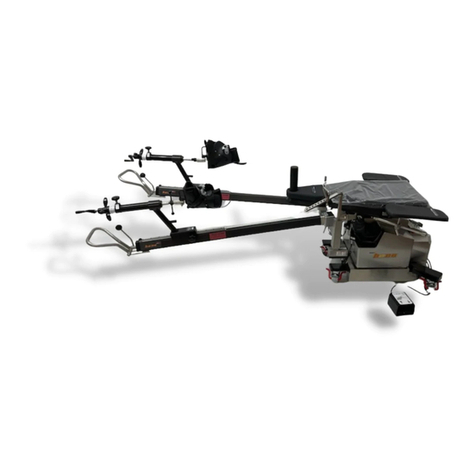
Mizuho osi Hana 6875 Operating instructions

6875 hana™
HIP AND KNEE ARTHROPLASTY
SURGERY TABLE
MAINTENANCE & REPAIR
hana™
Mizuho OSI
30031 Ahern Avenue
Union City, CA 94587-1234
Bus: 510-429-1500 Toll Free: 800-777-4674 Fax: 510-429-8500
http://www.mizuhosi.com/
0197
Manufactured by Mizuho OSI 2007 U.S. Patents Pending

6875 hana™ Table Maint./Repair Manual NW0467 Rev. B
1
TABLE OF CONTENTS
1.0 INTRODUCTION..................................................................................................................................................4
1.1 General Description.........................................................................................................................................4
1.2 Specifications....................................................................................................................................................5
1.3 Shipping.............................................................................................................................................................5
1.4 Storage ..............................................................................................................................................................5
1.5 Glossary of Terms............................................................................................................................................6
2.0 CONTROLS IDENTIFICATION.........................................................................................................................7
2.1 Table Orientation..............................................................................................................................................7
2.2 Major Controls Location ..................................................................................................................................7
2.3 Control Panel Identification.............................................................................................................................8
3.0 BASIC OPERATION...........................................................................................................................................9
3.1 Control Operation.............................................................................................................................................9
3.2 Caster Floor Locks...........................................................................................................................................9
3.3 Moving the Table..............................................................................................................................................9
3.4 Hand Pendant Control...................................................................................................................................10
3.5 Leg Spars........................................................................................................................................................11
4.0 THE ELECTRICAL SYSTEM...........................................................................................................................12
4.1 Description ......................................................................................................................................................12
4.2 On/Off Power Switch......................................................................................................................................12
4.3 Component Circuit Breakers ........................................................................................................................12
4.4 Power Cord.....................................................................................................................................................12
4.5 Battery System ...............................................................................................................................................13
5.0 INSPECTION......................................................................................................................................................14
5.1 Acceptance & Transfer..................................................................................................................................14
5.2 Per-procedure/Post-procedure.....................................................................................................................14
5.3 Semi-Annual....................................................................................................................................................14
6.0 FUNCTION CHECK...........................................................................................................................................15
7.0 MAINTENANCE.................................................................................................................................................18
7.1 Cleaning and Disinfection.............................................................................................................................18
7.2 Adjustment - Spar Ball-joint Lock Handle...................................................................................................19
7.3 Preventative Maintenance Checklist...........................................................................................................19
7.4 Disposal of Electrical Components..............................................................................................................19
8.0 TROUBLESHOOTING......................................................................................................................................20
8.1 Table Malfunction...........................................................................................................................................20
8.2 Diagnostics Tree.............................................................................................................................................20
8.3 On-line Diagnostics........................................................................................................................................21
9.0 REMOVAL and REPLACEMENT of COMPONENTS.................................................................................22
9.1 Hand Pendant Control...................................................................................................................................22
9.2 Foot Control.....................................................................................................................................................22
9.3 Motion-Control Module..................................................................................................................................23
9.4 Internal Batteries............................................................................................................................................24
9.5 Leg Spar Rotation Wheel..............................................................................................................................25
9.6 Table Lift Assembly........................................................................................................................................26
9.7 Tilt / Trendelenburg Assembly......................................................................................................................27
9.8 Femur Lift Assembly, Left / Right.................................................................................................................28
9.9 Caster(s)..........................................................................................................................................................28
10.0 TECHNICAL DRAWINGS and PARTS LISTS...........................................................................................29
10.1 Standard Components Identification Chart..............................................................................................29
10.2 Replacement / Spare Parts List.................................................................................................................29
10.3 Interconnect Diagram, 120VAC.................................................................................................................29
10.4 Interconnect Diagram, 230VAC.................................................................................................................29
10.5 Table Assembly Bill of Materials................................................................................................................29
11.0 OSI TECHNICAL SERVICE...........................................................................................................................30
European Union EC Representative
Medical Products International Europe, B.V.
Schutweg 13a
5145 NP Waalwijk
The Netherlands
Telephone: +31 (0) 416 563 754/Telefax: +31 (0) 416 563 926

6875 hana™ Table Maint./Repair Manual NW0467 Rev. B
2
IMPORTANT NOTICES
CAUTION:
To ensure safe operation of the equipment, please READ THESE INSTRUCTIONS
COMPLETELY and keep this manual readily available for future reference.
Carefully observe and comply with all warnings, cautions and instructions placed on the
equipment or described in this manual.
In this manual, the WARNING symbol is intended to alert the user to the
presence of important operation, maintenance, or safety instructions.
Dans ce manuel, le symbole AVERTISSANT est projeté d'alerter l'utilisateur
à la présence d'opération importante, l'entretien, ou les instructions de sûreté.
This device is to be used by trained professional personnel only.
Cet appareil va être utilisé le personnel en train professionnel seulement.
Classification and Table Rating
These products are considered Class I Exempt and have an of IPX-0 rating.
PROTECTION AGAINST ELECTRICAL SHOCK HAZARD:
This symbol indicates this equipment is an applied part, TYPE B and is
generally suitable for applications involving external or internal contact with the
patient, excluding the heart. The patient circuit is connected to protective earth
and this equipment should be connected only to outlets with a protective earth
ground.
LA PROTECTION CONTRE LE DANGER DE CHOC ELECTRIQUE:
Ce symbole indique que cet équipement est un B DE TYPE de partie appliqué
et est généralement convenable pour les applications contact impliquant,
externes ou internes avec le malade, excluant le coeur. Le circuit patient est
connecté à la terre protective et cet équipement devrait être seulement connecté
aux sorties avec un sol de terre protectif.
WARNING:
If the integrity of the power source is in doubt, the equipment shall be operated
from its internal electrical power source (battery).

6875 hana™ Table Maint./Repair Manual NW0467 Rev. B
3
AVERTISSANT:
Si l'intégrité de l'externe protectif terre est en doute, l'équipement sera opéré de
son interne électrique pouvoir (pile).
This symbol indicates an external ground stud that is required for use
when the AC power cable is not connected to a protective earth ground outlet in
your operating room or facility.
Ce symbole indique qu'un clou de sol externe qui est exigé pour
l'usage quand le câble d'alimentation n'est pas connecté à une sortie de sol de
terre protective dans votre pièce d'opération ou à la facilité.
To protect the patient, hospital staff and the table from any possible hazards, an
external ground wire connection is required between the external ground stud
and protective earth ground.
Pour protéger le malade, le personnel d'hôpital et la table des dangers possibles,
une connexion de fil de sol externe est exigée entre le clou de sol externe et le sol
de terre protectif.

6875 hana™ Table Maint./Repair Manual NW0467 Rev. B
4
1.0 INTRODUCTION
1.1 General Description
The OSI 6875 hana™ Surgery Table is designed to hold a patient undergoing the single incision, tissue
sparing Anterior Approach Total Hip Replacement and Total Knee Arthroplasty surgical procedures.
It is a stand-alone, single-pedestal, AC powered or internal battery operated table designed to position a
patient in a supine position during surgical procedures. The hana™ has three primary powered functions;
Height up/down, left/right lateral roll and Trendelenburg/Reverse Trendelenburg. Electromechanical
actuator-motors perform these motions which are controlled by means of a Hand Pendant with functions
clearly labeled. The table is also equipped with powered left and right Femur Lifts which are controlled by
a Foot Pedal providing the surgeon the ability to raise and lower the Femoral Hook during the Anterior
Approach Total Hip Arthroplasty.
Four (4) independent, manual caster floor locks are utilized to stabilize the table in the operating location.
An auxiliary control panel is provided for control of the table if the hand pendant is lost or becomes
disabled.
6875 hana™ Table, right-side view.

6875 hana™ Table Maint./Repair Manual NW0467 Rev. B
5
1.2 Specifications
The 6875 hana™ Table is Class 1 Exempt, Type B Medical Device with an IPX-O rating.
The table is designed to position a patient weighing up to 450 pounds (205 kg).
Table length (with Leg Spars installed and parallel) is 125 inches (3175 mm).
Table width (at base) is 35 inches (889 cm).
NOTE: Maximum width with Leg Spars positioned outward could exceed 10 feet (3048mm).
Table height with all standard components attached will operate within 8-foot ceiling area (2338 mm).
Table weight is 879 pounds (400kg).
Table shipping weight is 1,000-1,200-pounds (450-545kg).
Table Top length is 48.5 inches (1231 cm).
Table Top width is 21.5 inches (546 mm).
Table Top height range (measured from the floor) is 29 inches to 49 inches (736mm to 1,245mm).
Table Top lateral tilt range is +/- 12 degrees.
Table Top Trendelenburg (pitch) range is +/- 12-degrees (+/- 2 deg).
Table Top maximum deflection under full load is less than 2 inches (51 mm) at the cantilever end.
Table Top radiolucent equivalency is less than 1-mm aluminum.
Table input power requirement is: 100 VAC, 50/60 Hz, 4 Amps; 120 VAC, 60 Hz, 4 Amps; or 220 VAC, 50
Hz, 2 Amps, 10% / 6 minute Duty Cycle
The table may also be operated on internal battery power: 24VDC battery voltage, 15Amps, 360 Watts
The expected working life of a fully charged battery is approximately 12 hours at a 10% duty cycle.
1.3 Shipping
The 6875 hana™ Table must be shipped using appropriate OSI Shipping methods and Instructions.
During shipment the 6875 hana™ Table is to be kept in an environment within the following limits:
•Ambient temperature: -4 degrees F. (-20 degrees C) to 122 degrees F (+ 50 degrees C)
•Relative humidity from 10% to 100%, including condensation
•Atmospheric pressure from 50k to 110k Pascal
1.4 Storage
When not in use the 6875 hana™ Table should be stored in a clean dry environment with temperature
between 32°F (0 degrees C) & 120°F (49 degrees C).
To insure the internal battery is always fully charged and ready for use, the table must be stored with the
power cord plugged into a grounded, hospital grade AC power source (100 VAC, 120 VAC, or 230 VAC)
and with the On/Off Power Switch toggled “ON”.

6875 hana™ Table Maint./Repair Manual NW0467 Rev. B
6
1.5 Glossary of Terms
The glossary of terms assumes the patient is supine with their head at the “Head-end of the Table”
(toward Control Panel) and their feet are at the “Foot-end of the Table” (toward Leg Spars). The Hand
Pendant functions are oriented for this position only.
“Head End of table” refers to the end of the table where the power cord, "ON/OFF" Power Switch, and
Control Panel are located; otherwise referred to as the “pedestal end”.
“Foot End of table” refers to the opposite end of the table also referred to the “leg spar end".
“Control Panel” is a panel of buttons and lights located on the back of the pedestal.
“Pedestal” refers to the main column structure that supports the tabletop.
“Left side of the table” refers to the table as you stand at the head end of table.
This also corresponds to the Hand Pendant button labeled “LEFT LATERAL ROLL”.
“Right side of the table” refers to the table as you stand at the head end of table.
This also corresponds to the Hand Pendant button labeled “RIGHT LATERAL ROLL”.
“Raise the table” refers to raising the height of the table.
This also corresponds to the Hand Pendant button labeled “HEIGHT UP”.
“Lower the table” refers to lowering the height of the table.
This also corresponds to the Hand Pendant button labeled “HEIGHT DOWN”.
“Trendelenburg” refers to lowering the height of the head-end of the table only. The corresponding
Hand Pendant button is labeled “TREN”.
“Reverse Trendelenburg” refers to raising the height of the head-end of the table only. The
corresponding Hand Pendant button is labeled “REV TREN”.
”Return to Level” or “Level the table” refers to returning the tabletop to a state of level regardless of
height. The corresponding Hand Pendant button is labeled “RETURN TO LEVEL”. Holding the “RETURN
TO LEVEL” button longer than approximately three seconds will also lower the tabletop to its lowest
position.
“Hospital Grade" outlet refers to a 120VAC outlet properly wired with earth ground: Neutral to Common
= 120VAC; Neutral to Ground = 120VAC; Common to Ground less than zero point five (0.5) VAC.

6875 hana™ Table Maint./Repair Manual NW0467 Rev. B
7
2.0 CONTROLS IDENTIFICATION
2.1 Table Orientation
The major components of the 6875 hana™ Table are identified below. The table is described as having a
"Head End" and a "Foot End". The On/Off Power Switch and the Power Cord receptacle are located at
the "Head End" of the table.
Right-side View with Patient in Supine Position
2.2 Major Controls Location
The Control Panel, On-Off Power Switch, Power Cord receptacle and Model Number/Serial Number
identification label are located at the head-end of the table.
Head End Control Panel

6875 hana™ Table Maint./Repair Manual NW0467 Rev. B
8
2.3 Control Panel Identification
Control Panel
The Control Panel is divided into 3 sections:
Section 1: Femur Lift control section. Selection switch to change between Right and Left Femur Lift
operation. Indicators to show if Femur Lift is connected (Left, Right). Indicator to show if Foot Pedal is
connected. (Indicators: Lit: Parts are connected, Not Lit: Parts not connected)
Section 2: Control Pad. The Control Pad and the Hand Pendant Control Table Up/Down, Lateral Tilt and
Trendelenburg. See section 3.4 for operation of the Hand Pendant.
Section 3: has indicators to notify user of the following conditions:
1. Battery Condition
a. Charge: Battery power low or no battery installed.
b. OK: Battery has sufficient power to operate table
2. AC Power: Indicates table is running on line (100, 110, 220)V power from wall receptacle.
3. Battery Power: Table is on running from internal batteries.
1 2 3
Femur Lift
Control
Section
Power
Indicator
Section
Control Pad

6875 hana™ Table Maint./Repair Manual NW0467 Rev. B
9
3.0 BASIC OPERATION
3.1 Control Operation
Plug the power cord into the power cord receptacle, located at the Head End of the table and into a
properly grounded receptacle. Refer to the Model/Serial Number label on the Head End of the table for
input voltage requirements. Toggle the On/Off Power Switch to "ON". The green light in the switch
illuminates indicating that AC power is applied to the table. This switch functions as a combination on/off
power switch, circuit breaker and pilot light.
3.2 Caster Floor Locks
Prior to transferring a patient onto the table and at all times when the table is in use, ensure all four (4)
independent, manual caster floor locks are in the locked position. To lock the caster lock, step on the foot
pad and depress to the floor. To unlock, slide foot under pad and lift to disengage lock.
Floor Lock in the Unlocked Position Floor Lock in the Locked Position
3.3 Moving the Table
After all four (4) floor locks are unlocked the table can be rolled for relocation. It is best that the table be
rolled with the Foot End pointed in the direction of travel. The 6875 hana™ Table is heavy and a
minimum of two people should move it, one at the Head End, one at the Foot End and care should be
taken to control it when rolling.
CAUTION: If the table is allowed to roll too fast, it may be difficult to stop or turn.
LA PRUDENCE: Il la Table est permise de rouler aussi pour jeûner, ce sera difficile à arrêter ou
tourner.

6875 hana™ Table Maint./Repair Manual NW0467 Rev. B
10
3.4 Hand Pendant Control
The 6875 hana™ table is controlled by means of a Hand Pendant. The Hand Pendant is plugged into the
receptacle labeled “HAND PENDANT” on the Control Panel. Flip main “ON/OFF Power Switch to “OFF”.
Plug in Hand Pendant connector and rotate screw-locking collar clockwise until hand tight. Flip main
“ON/OFF Power Switch to “ON”, wait twenty seconds for table to “boot-up” and run self-diagnostics (all
Hand Pendant lights will cycle on and off, then remain on). To operate any of the desired functions, press
and hold the appropriate button on the Hand Pendant until the desired position is achieved.
The Hand Pendant is equipped with a "RETURN TO LEVEL" button. This button functions to first, level
the Lateral Roll; second, level the Trendelenburg; third, re-level lateral roll; and fourth, brings the table to
its lowest position. A delay of three (3) seconds is programmed after the re-level of lateral roll is
completed before returning to its lowest position. To achieve the final position, this button must be held
continuously until motion stops. The controller considers the table to be level if it is within +/- two (2)
degrees. If the "RETURN TO LEVEL" button is pressed while the table is within this range, it may not
move. If it is required to adjust the table to a position closer to zero degrees, press the appropriate
function button on the Hand Pendant until the desired position is achieved.
6875 hana™ Table Hand Pendant

6875 hana™ Table Maint./Repair Manual NW0467 Rev. B
11
3.5 Leg Spars
The 6875 hana™ table is equipped with two adjustable Leg Spars. Each
Leg Spar is designed to support the foot in the traction boot and allow for abduction, adduction, raising or
lowering of the leg. When the leg is in a desired position the spar can be locked to maintain that position.
A dial is provided to gauge the degree of internal and external rotation and should be zeroed out and
locked in place utilizing the thumb screw when the foot is in the neutral position. Gross and fine traction
are also controlled at the foot end of the spar.
To unlock the spar to abduct, adduct, raise or lower the leg, hold the spar with one hand on the looped
handle and move the knobbed lever from the Locked to Unlocked position (refer to picture below). When
you have positioned the leg where needed lock the spar by returning the knobbed handle to the Locked
position. The spar should be held by the looped handle at all times when it is not locked.
Spar Ball Joint Lock/Unlock Loop Handle of Leg Spar
CAUTION: Leg Spars can be damaged if allowed contact with floor during table operation. During
table movement, clear area of any obstructions or obstacles.
LA PRUDENCE: les Perches de Jambe peuvent être endommagées si a permis le contact avec le
plancher pendant l'opération de table. Eclaircir de n'importe quelles obstructions
ou de n'importe quels obstacles pendant le mouvement de table.
6875 hana™ Table with Leg Spars Attached & Set Up for Bilateral Total Hip Replacement

6875 hana™ Table Maint./Repair Manual NW0467 Rev. B
12
4.0 THE ELECTRICAL SYSTEM
4.1 Description
The electrical system provides control of all table functions and is comprised of a power cord, an On/Off
circuit-breaker switch, wire harnesses, a power supply, a controller circuit, a hand pendant, floor lock
jackscrew-actuators, and various electromechanical actuators. Electric motor-driven lead-screw actuators
manipulate the table height, lateral roll and Trendelenburg functions. The input power requirement is 100
VAC 50/60Hz, 4 Amp, 120 VAC 60Hz, 4 Amp or 230 VAC 50Hz, 2 Amp, 10% / 6 minute Duty Cycle as
indicated on the Serial Number label. Refer to 6875 hana™Table Electrical Interconnect Diagram in
maintenance manual for details of the electrical system.
4.2 On/Off Power Switch
An illuminated On/Off Power Switch and circuit breaker is located on the Head End of the table. When
illuminated, it indicates that the table is plugged into a live electrical outlet and the power is on. (When the
table is turned on using battery power, this switch will not illuminate). This switch also serves as a circuit
breaker. In the event of an overload condition this switch will trip off. To reset, push to the OFF position
and then the ON position.
NOTE: Determine the source of the overload prior to resetting this switch.
4.3 Component Circuit Breakers
The electrical system includes individual component 24-volt circuit breakers, located at the head end of
the table. If a short circuit occurs in the low voltage circuit, the breaker will trip as indicated by a button
protruding from the access hole. To reset, press the button in and release.
NOTE: Determine the source of the overload prior to resetting this button.
4.4 Power Cord
The table is equipped with a detachable standard IEC power cord with the appropriate 120 VAC hospital
grade connector (230 volt versions do not include the power connector). The power cord is connected to
the table at the IEC power entry socket located near the "ON/OFF" switch, at the head end control panel.
Head End Base and Control Panel

6875 hana™ Table Maint./Repair Manual NW0467 Rev. B
13
4.5 Battery System
The 6875 hana™ Table is equipped with a battery system, which consists of two 12 volt batteries in
series to provide 24 volts. Due to the relatively low power consumption of the 6875 hana™ Table, it can
be used on battery power for up to 12 hours at 10% duty cycle.
WARNING:
If the integrity of the external protective earth conductor is in doubt, the equipment shall be
operated from its internal electrical power source (Battery).
AVERTISSANT:
Si l'intégrité de l'externe protectif terre est en doute, l'équipement sera opéré de son interne
électrique pouvoir (pile).
This symbol indicates an external ground stud that is required for use when the AC power
cable is not connected to a protective earth ground outlet in your operating room or facility.
Ce symbole indique qu'un clou de sol externe qui est exigé pour l'usage quand le câble
d'alimentation n'est pas connecté à une sortie de sol de terre protective dans votre pièce
d'opération ou à la facilité.
To protect the patient, hospital staff and the table from any possible hazards, an external ground
wire connection is required between the external ground stud and protective earth ground.
Pour protéger le malade, le personnel d'hôpital et la table des dangers possibles, une connexion
de fil de sol externe est exigée entre le clou de sol externe et le sol de terre protectif.
Battery charge status is shown via a LED on the hand pendant labeled "Battery Status".
If illuminated green = OK.
If illuminated red = charge.
If a recharge is required, charge a minimum of 3 hours. A full charge should be available after 18 hours.
To charge the batteries simply plug the power cord into an appropriate “hospital grade” outlet and turn the
on/off power switch “ON”. It is important to plug in the table as soon as possible after the battery status
LED is illuminated red. Life of the battery can be shortened if the table remains unplugged and turned on
for extended period of time. While in storage it is desirable that the table be plugged in and the power
switch turned on so that the batteries remain charged. If this is not possible, the batteries must be
charged for at least three hours a week. This can be accomplished when using the table under AC power
since the system batteries are automatically charged while the table is plugged in and turned on.
Both batteries should be replaced every five (5) years or when they fail to hold a charge. See Section 7.4
or User Guide for disposal instructions.

6875 hana™ Table Maint./Repair Manual NW0467 Rev. B
14
5.0 INSPECTION
5.1 Acceptance & Transfer
Please refer to the 6875 hana™ Table User Guide (part number NW0466).
5.2 Per-procedure/Post-procedure
Please refer to the 6875 hana™ Table User Guide (part number NW0466).
5.3 Semi-Annual
It is recommended to perform a Preventative Maintenance (PM) check of your 6875 hana™ Table (see
Section 7 Maintenance).
A PM Checklist is available from OSI Technical Service Department (800-777-4674).

6875 hana™ Table Maint./Repair Manual NW0467 Rev. B
15
6.0 FUNCTION CHECK
Perform all steps in this procedure. For a complete definition of terms used in this procedure, please refer
to the “Glossary of Terms” section of the manual.
1. Plug in the Hand Pendant.
Verify the main “ON/OFF” Power Switch is “OFF” (located on table base front, below Control Panel).
Plug the Hand Pendant cable-connector into the "HAND PENDENT" receptacle (located on table
base front, below Control Panel).
2. Plug the Foot Pedal into the port at the foot end of the table base. The flange should be flush or
below surface of receptacle.
3. Attach Right & Left Femur Lift assemblies, and connect their electrical cords.
Attach the right or left Femur Lift to the corresponding mounting bracket by sliding into the bracket
and secure by turning the locking knob clockwise until hand tight.
Attach the power cord connector extending from the mounting bracket to the port on the bottom of the
Femur Lift and rotate screw-locking collar clockwise until hand tight.
4. Apply AC power.
Plug the AC Power Cord into an appropriate “hospital grade” AC outlet and into the Power
Receptacle (located on rear of table base).
NOTE: Verify proper outlet voltage for your model table.
Flip the main “ON/OFF” Power Switch to “ON” and confirm the following:
4.1. The main “ON/OFF” Power Switch illuminates indicating AC power is applied.
4.2. The “AC Power” light on Control Panel illuminates green.
NOTE: The table may be used with AC power even if the red “CHECK BATTERY” light is on
(indicating batteries needs charging).
5. Control Panel check.
5.1. Power Status Lights.
Observe the table Power Status lights located on the Control Panel.
•If green “AC Power” light is on, continue to Battery Power Check section below.
•If red “Battery Check” light is on, charge battery for a minimum of 3 hours (leave Power Cord
plugged in and main “ON/OFF” Power Switch “ON”). If red “Battery Check” light remains on
after three (3) hours, continue to charge battery for up to 18 hours.
•If green “Battery OK” light comes on during charging, continue checks below.
•If green “Battery OK” light does not come on after 18 hours of charging, refer to Battery
System, Section 4.4.
5.2. Confirm green “FOOT SWITCH CONNECTED” light is on.
5.3. Confirm green “LEFT LIFT CONNECTED” light is on.
5.4. Confirm green “RIGHT LIFT CONNECTED” light is on.
5.5. Switch “Left/Right Femur Lift Switch” to “LEFT HOOK”; confirm green “LEFT FEMUR LIFT” light
is on.
5.6. Switch “Left/Right Femur Lift Switch” to “RIGHT HOOK”; confirm green “RIGHT FEMUR LIFT”
light is on.
5.7. While using the Control Panel function buttons;
•Press and hold "HEIGHT UP" button. Confirm the tabletop moves up.
•Press and hold “HEIGHT DOWN" button. Confirm the tabletop moves down.
•Press and hold "REV. TREN" button. Confirm foot-end of tabletop becomes lower than the
head-end.
•Press and hold "TREN" button. Confirm head-end of tabletop becomes lower than the foot-
end.
•Press and hold "LEFT LATERAL ROLL" button. Confirm the tabletop tilts to the left.
•Press and hold "RIGHT LATERAL ROLL" button. Confirm the tabletop tilts to the right.

6875 hana™ Table Maint./Repair Manual NW0467 Rev. B
16
•Move Table Top out of level by raising height approximately two inches, tilting tabletop (left or
right) and activate Trendelenburg approximately five degrees. Press and hold the "RETURN
TO LEVEL" button and observe that the tabletop:
1) Levels the Lateral Roll.
2) Levels the Trendelenburg.
3) Re-levels the Lateral Roll.
4) After a three (3) second delay, lowers to its lowest position.
Confirm that the table top is level and at its lowest height position.
6. Hand Pendant check.
6.1. Confirm green “AC” Power light is on.
6.2. Confirm green “Battery Status” light is on.
6.3. While using the Hand Pendant function buttons;
•Press and hold "HEIGHT UP" button. Confirm the tabletop moves up.
•Press and hold “HEIGHT DOWN" button. Confirm the tabletop moves down.
•Press and hold "REV. TREN" button. Confirm foot-end of tabletop becomes lower than the
head-end.
•Press and hold "TREN" button. Confirm head-end of tabletop becomes lower than the foot-
end.
•Press and hold "LEFT LATERAL ROLL" button. Confirm the tabletop tilts to the left.
•Press and hold "RIGHT LATERAL ROLL" button. Confirm the tabletop tilts to the right.
•Move Table Top out of level by raising height approximately two inches, tilting tabletop (left or
right) and activate Trendelenburg approximately five degrees. Press and hold the "RETURN
TO LEVEL" button and observe that the tabletop:
1) Levels the Lateral Roll.
2) Levels the Trendelenburg.
3) Re-levels the Lateral Roll.
4) After a three (3) second delay, lowers to its lowest position.
Confirm that the table top is level and at its lowest height position.
7. Battery Power Check. Ensure the Foot Pedal and Femur Lift function correctly. On the Control
Panel verify the Femur Lift is connected by the corresponding LED illuminating when the appropriate
lift is selected. Depress the Foot Pedal, “UP” and observe the lift raise to its fullest height and then
press “DOWN” and observe the lift lower to its lowest position. Complete this process for both the
right and left Femur Lifts.
7.1. Confirm Green Battery OK light on Control Panel and Hand Pendant are ON. If not, charge
Battery per section 4.4.
7.2. With table main “ON/OFF” Power switch “ON”, unplug AC Power Cord from AC outlet or table
Power Receptacle and confirm the following:
•Green “AC POWER” light on Control Panel goes dark. Green “BATTERY POWER” light
comes on.
•Green “BATTERY OK” remains on.
•The main (illuminated) ON/OFF Power Switch goes dark.
7.3. Perform Hand Pendant check using battery power.
•Press and hold "HEIGHT UP" button. Confirm the tabletop moves up.
•Press and hold “HEIGHT DOWN" button. Confirm the tabletop moves down.
•Press and hold "REV. TREN" button. Confirm foot-end of tabletop becomes lower than the
head-end.
•Press and hold "TREN" button. Confirm head-end of tabletop becomes lower than the foot-
end.
•Press and hold "LEFT LATERAL ROLL" button. Confirm the tabletop tilts to the left.
•Press and hold "RIGHT LATERAL ROLL" button. Confirm the tabletop tilts to the right.

6875 hana™ Table Maint./Repair Manual NW0467 Rev. B
17
•Move tabletop out of level by raising height approximately two inches, tilting tabletop (left or
right) and activate Trendelenburg approximately five degrees. Press and hold the "RETURN
TO LEVEL" button and observe that the tabletop:
1) Levels the Lateral Roll.
2) Levels the Trendelenburg.
3) Re-levels the Lateral Roll.
4) After a three (3) second delay, lowers to its lowest position.
Confirm that the table top is level and at its lowest height position.

6875 hana™ Table Maint./Repair Manual NW0467 Rev. B
18
7.0 MAINTENANCE
7.1 Cleaning and Disinfection
NOTE: Never pour any liquid directly onto the table. Never subject the 6850 Table to an equipment
washing machine.
USE OF IODOPHORS WILL CAUSE STAINING.
Table Exterior:
1. Exterior surface should be regularly wiped clean with a mild detergent solution and wiped dry with a
soft lint-free cloth.
2. Care should be taken to avoid exposing the table to excessive moisture. Flooding, fogging or steam
cleaning is not recommended.
3. Blood or other fluids, etc., if allowed to remain on the table for a long period of time, will require
special cleaning to remove. A 5% acetic acid solution or white vinegar and water solution is
especially good for this purpose.
4. Cleaning with a good commercial cleaning compound, such as Stainless Steel Magic or Acme White
Finish, and then buffing the surface by hand can correct staining and discoloration of plated or
stainless steel surfaces only.
5. To disinfect exterior surfaces use a quaternary ammonium or similar type disinfectant compound
according to manufacturer's directions for use. Wipe dry with a soft lint-free cloth.
NOTE: Failure to thoroughly dry surface after cleaning and disinfecting may result in rust.
Casters:
Casters should be cleaned and disinfected in the same manner as table exterior. Access to the casters is
achieved by removing the sheet metal enclosures at each end of the table base.
NOTE: Before removing any sheet metal covers the table must be turned off and unplugged. Dangerous
high voltage may be present in the circuitry under the covers. Only trained technicians should perform this
task.

6875 hana™ Table Maint./Repair Manual NW0467 Rev. B
19
7.2 Adjustment - Spar Ball-joint Lock Handle
Overview:
With break-in wear the patient leg “Spar Ball Joint Lock” handle (Lock Handle) may require adjustment to
allow proper functionality. If the Spar does not move freely when the Lock Handle is in “Unlock” position,
or does not hold position when handle is in “Locked” position, adjustment is required.
Tools Required:
Wrench, open, box-end, or adjustable, 5/8th inch.
Procedure Overview:
1. Test Leg Spar.
2. Lock Leg Spar in place.
3. Loosen Lock Nut and Lock Handle.
4. Reposition Lock Handle and retighten Lock Nut.
5. Re-test Leg Spar
Procedure:
1. While firmly holding Leg Spar from dropping, rotate Lock Handle (item 1) counter-clockwise to the
“UNLOCK” position and determine if Leg Spar is free to move without binding or friction. If much
binding/friction is felt adjust Lock Handle position
2. Rotate Lock Handle clockwise toward the “LOCKED” position until Leg Spar is held firmly in place
parallel to the floor and in-line with the table.
3. Using 5/8th inch wrench, loosen Lock Nut (item 2) until Lock Handle is free to be repositioned.
There are serrated teeth on both the Lock Handle and mating fitting.
4. Reposition Lock Handle to approximately the two-o’clock position and with serrated teeth
engaged, retighten Locking Nut with the 5/8th inch wrench.
5. While firmly holding Leg Spar from dropping, rotate Lock Handle counter-clockwise to the
“UNLOCK” position and determine that Leg Spar is free to move without binding or friction.
7.3 Preventative Maintenance Checklist
A Preventative Maintenance (PM) Checklist is available from OSI Technical Service Department (800-
777-4674).
7.4 Disposal of Electrical Components
Refer to User Guide for disposal of electrical components.
Other manuals for Hana 6875
1
Table of contents
Other Mizuho osi Medical Equipment manuals
Popular Medical Equipment manuals by other brands

Enabling Technologies
Enabling Technologies Dynamique Biski owner's manual

Invacare
Invacare 1426875 user manual

Tommee Tippee
Tommee Tippee NC003 Instructions for use

3A HEALTH CARE
3A HEALTH CARE MINIASPEED Battery Evo Plus instruction manual

EarlySense
EarlySense InSight AME-01350-US user guide

Braun
Braun perfusor compact Service manual

Top shelf Orthopedics
Top shelf Orthopedics Hinge Knee Plus Instructions for use

BIOTRONIK
BIOTRONIK Edora 8 SR-T Technical manual

AirSep
AirSep LifeStyle Patient manual

Aquolab
Aquolab Aquolab Basic user manual

Fresenius Kabi
Fresenius Kabi Volumat Agilia Technical manual

E. I. Medical Imaging
E. I. Medical Imaging Ibex EVO user guide