Mizuho V Attachment User manual

MES-CK08-115-80EN Ver.1 2023-07-10
V Attachment for Traction Device
(V Attachment II Side Rail Type)
Operator’s Manual
Table of Contents
1. Introduction..........................................2
2. Component..........................................3
3. Instructions for use..............................4
4. Maintenance/Inspection.......................9
5. Specifications....................................10
Be sure to read this instruction manual before using this product.
Keep this manual available for reference when needed.

2
1. Introduction
1-1. Intended purpose
This product is an accessory that is attached to the operating table, and it is a device onto which
the Traction Device is attached during traction surgery.
1-2. Intended user
This product is to be used by health care professionals, including but not limited to surgeons,
nurses and biomedical technicians.
1-3. Warning/Caution
To ensure safe operation and proper functionality, please read the following instructions
thoroughly before use and follow them carefully. Failure to follow these instructions could lead to
serious injury of the patient or the user or damage to this product.
If this indication is ignored and the product is incorrectly used, death and/or serious
injury may result.
•When using operating table accessories, always pay close attention to the
patient. Patients left in the same posture for an extended period of time are at risk
for developing nerve paralysis and/or bedsores.
If these indications are ignored and the product is incorrectly used, injury and/or
damage to property may result.
•This product isonly validated for use with Mizuho operating tables.
•When working with the operating table, take care not to allow this product to
make contact or interfere with the tabletop or with other tools and appliances
used in combination with this product. Otherwise the product could break.
•For hygiene, be sure to use sterilized drapes on the areas on this product where
the patient comes into contact with it.
1-4. Symbol mark for labeling
MD : Medical Device

3
2. Component
The components of this product are as follow.
V Attachment II Side Rail Type
Component
Material
①Fixing handle Stainless steel
②Arm fixing handle Stainless steel
③V Attachment II Stainless steel
④Safety hook Stainless steel

4
3. Instructions for use
The following describes how to attach, detach and operate this product.
For details on how to operate the operating table, refer to the operating table’s operator’s manual.
For details on how to operate each Traction Device product, refer to the operator’s manual CK08-
115-01.
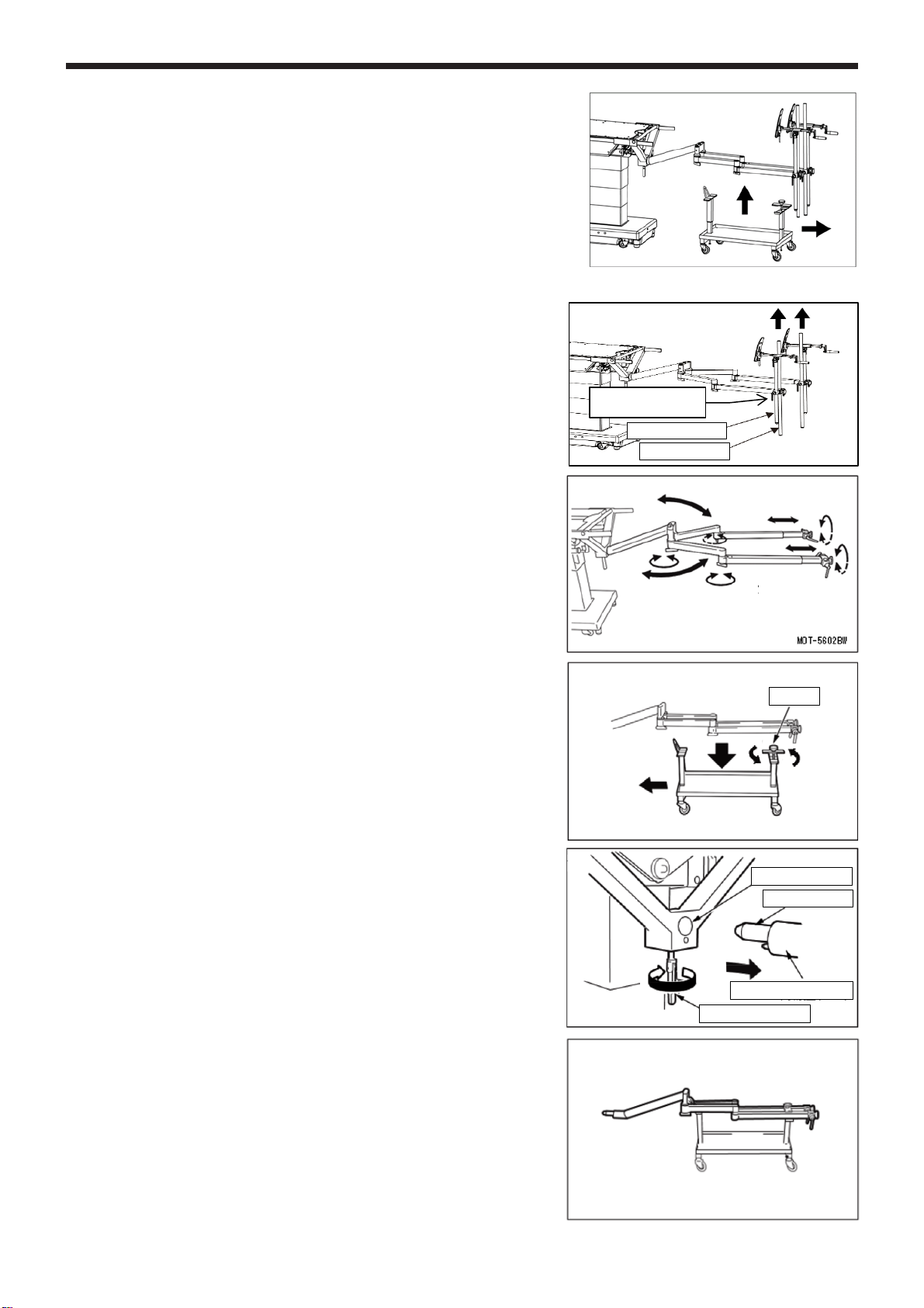
Ensure all fixing handles are tight. Loose condition can cause the product to come
off or move, which may result in a patient injury.
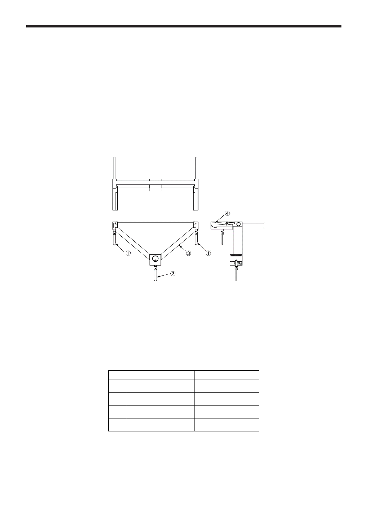
•When attaching the V Attachment II Side Rail Type, confirm that it is fully inserted
into the operating table’s side rail, then fix it.
If the devices are not fully inserted, then the devices may come off or move,
which may result in a patient injury. In addition, check that the safety hooks are
hooked onto the operating table. If the safety hooks are not hooked onto the
operating table, the hook functions will be insufficient.
•Do not use the V Attachment II Side Rail Type except for at the operating table’s
slide function’s center position. Doing so may cause it to become unstable, and
the patients may fall.
•When moving the arm (Traction Device Arm and Extension Arm) from the
accessory cart to the Cart for Traction Arm, be sure to move it with two or more
people. Not doing so, may result in it falling, and causing injuries, or it getting
damaged.
•When lowering the operating table’s tabletop with the V Attachment II Side Rail
Type attach
ed, do not lower it in the position where it slides toward the head from
the center position. Doing so may cause the arm fixing handle’s tip to come into
contact with the column and get damaged.
•After connecting the V Attachment II Side Rail Type and the operating table,
elevate the operating table and check that the arm fixing handle is tightened
before releasing the arm from the Cart for Traction Arm.
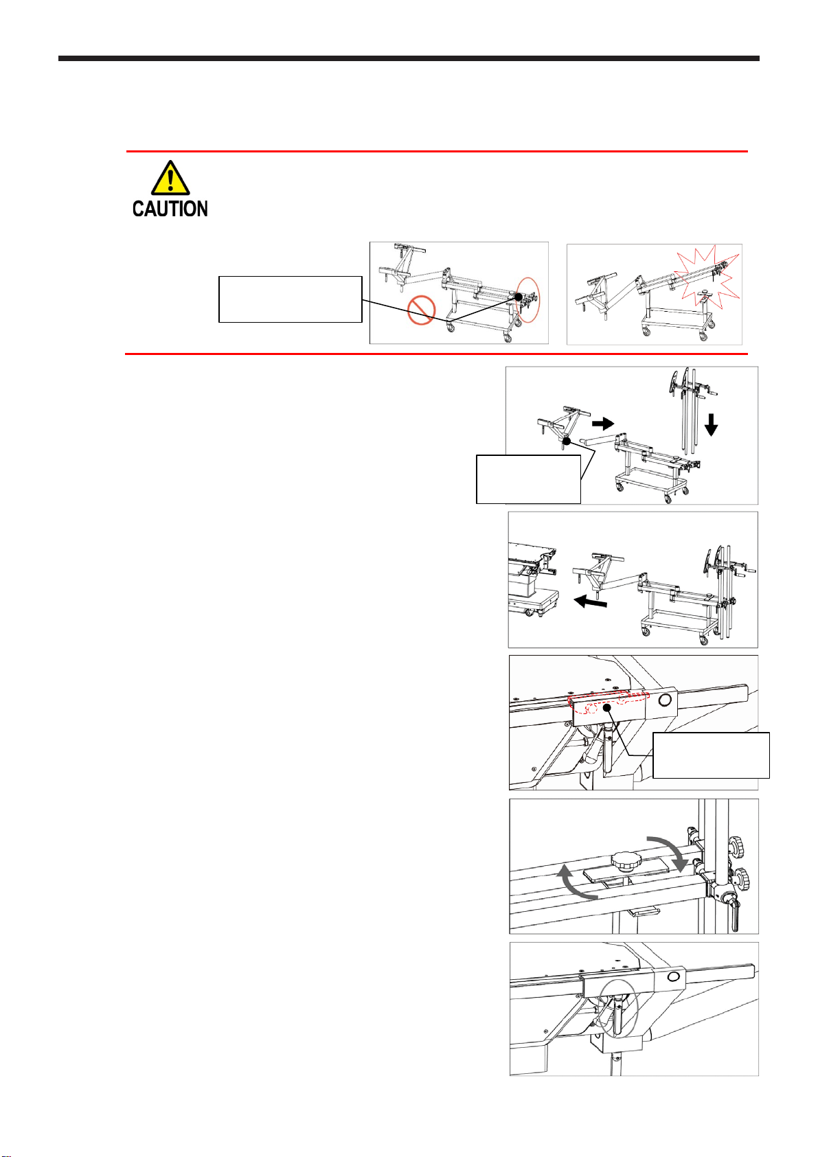
<Attachment> Only for when first attaching the V Attachment II Side Rail Type onto the
operating table
1. Set the operating table’s tabletop in a level
position and the slide in the center position.
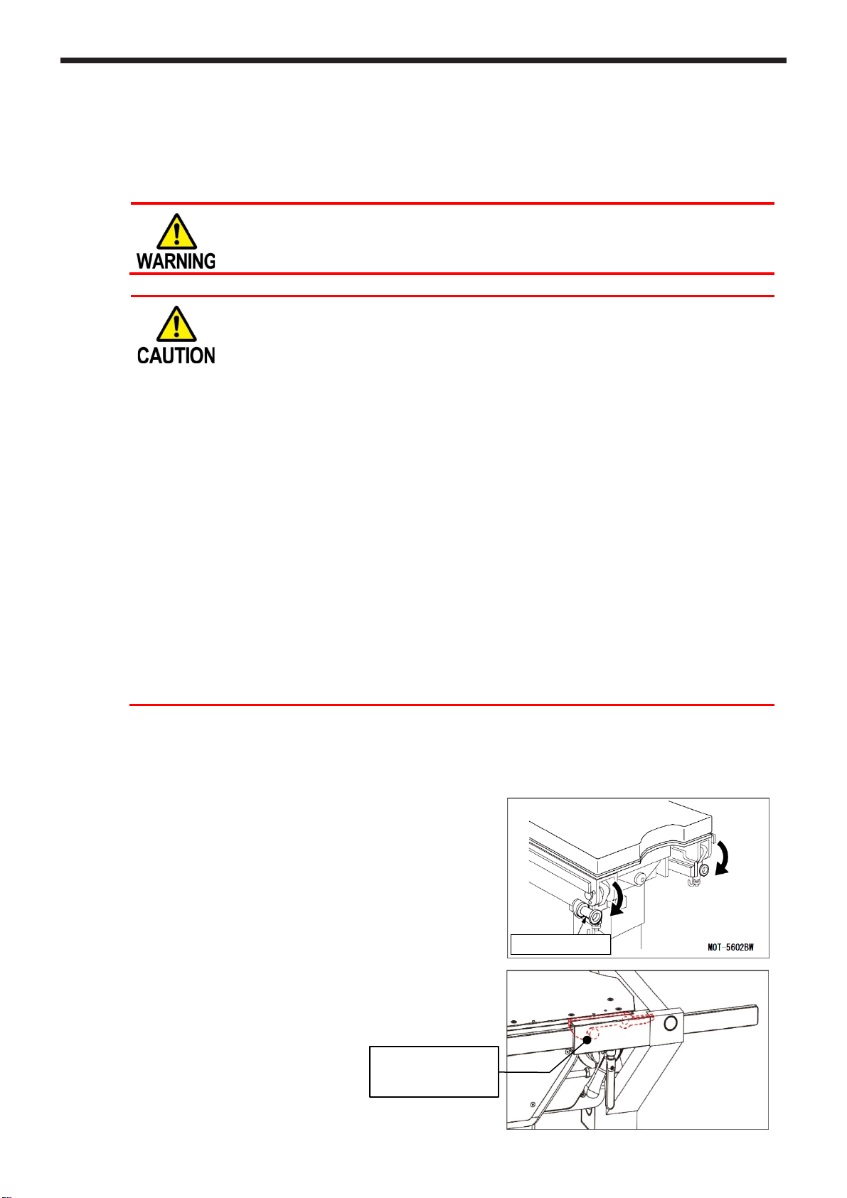
2. Detach the operating table’s leg plate.
(For the MOT-5602BW and MOT-VS700, after
detaching the leg plate, lower the leg plate clutch,
and leg plate insertion section by 90 degrees.)
3. Insert the V Attachment II Side Rail Type into the
operating table’s seat plate rail.
Check that the safety hooks are hooked onto the
operating table’s collar at this time.
Check that the hooks
(red) are hooked onto
the collar
Leg plate clutch

5
4. Turn the right and left fixing handles to fix
them.
5. Move the arms (Traction Device Arm and
Extension Arm) from the accessory cart to
the Cart for Traction Arm and fix them with
the handle.
6. Confirm that the operating table’s tabletop is
in the slide operation range’s center position,
and adjust the operating table’s elevation height
so that it is the same as the height of the insertion
section and the height of the insertion shaft for
the V Attachment II Side Rail Type.
7. Loosen the V Attachment II Side Rail Type’s
arm fixing handle.
8. Fully insert the Traction Device Arm’s insertion
shaft into the V Attachment II Side Rail Type’s
insertion section.
9. Tighten the arm fixing handle.
10. Release the Cart for Traction Arm’s handle,
and set the arms so that they are out of the way.
11. Elevate the operating table’s tabletop.
After the arms are moved away from the
Cart for Traction Arm, move the Cart for
Traction Arm.
12. Articulate the Extension Arm and operate the
telescopic handles to set them.
13. Attach the Support Rods and the Traction
Device into the insertion sections on the
tips of the Extension Arm, and turn the height
adjustment handle to fix them.
Insertion section
Traction Device Arm
Arm fixing handle
Insertion shaft
Handle
Height adjustment handle
Traction Device
Support Rods
Loosen Loosen
Fix
Fix
Fixing handle V Attachment II
Side Rail Type
Handle
Traction
Device Arm
Accessory cart Extension
Arm

6
<Attachment> The method whereby the V Attachment II Side Rail Type and the Traction
Device Arm and the Extension Arm are first connected, only applies to the
operation methods for the V Attachment II Side Rail Type.
•When the V Attachment II Side Rail Type is being attached, simultaneously
attach the Traction Device and the Support Rods. If just the V Attachment II Side
Rail Type is attached onto the Cart for Traction Arm, then any objects placed on
the cart may tip over.
1. Move the arms (Traction Device Arm and
Extension Arm) from the accessory cart to
the Cart for Traction Arm.
2. Attach the V Attachment II Side Rail Type,
the Traction Device and the Support Rods onto
the Traction Device Arm and the Extension Arm
that are loaded onto the Cart for Traction Arm.
3. Confirm that the V Attachment II Side Rail Type’s
attaching position (the operating table’s elevation
height and the slide operation range’s center point)
is correct.
(If the Cart for Traction Arm is correctly adjusted,
then the heights for the upper surface of the
operating table’s seat plate rail and the V
Attachment II Side Rail Type’s openings will
almost be the same height.)
4. Insert the V Attachment II Side Rail Type that is
loaded onto the Cart for Traction Arm into the
operating table’s seat plate rail.
Check that the safety hooks are hooked onto
the operating table’s collar at this time.
5. Release the Cart for Traction Arm’s handle.
6. Tighten the V Attachment II Side Rail Type’s fixing
handles.
Check that the arm
fixing handle is
tightened
Check that the hooks
(red) are hooked onto
the collar
Attach the Traction Device
and the Support Rods

7
7. Elevate the operating table’s tabletop.
After the arms are moved away from the Cart for
Traction Arm, move the Cart for Traction Arm.
<Detachment> For when first detaching the Traction Device Arm and the Extension Arm
1. Loosen the height adjustment handles for the
Support Rods and the Traction Device, and detach
them from the insertion sections (inside) on the
tips of the Extension Arm.
2. Articulate the Extension Arm and operate
the telescopic handles to set them to release.
3. Set the Extension Arm in a straight line as
per the figure on the right.
4. Position the Cart for Traction Arm directly
under the Extension Arm.
5. Adjust the operating table’s elevation height
so that the Extension Arms are in contact
with the Cart for Traction Arm.
6. Tighten the Cart for Traction Arm’s handle,
and fix the arms.
7. Loosen the arm’s fixing handle.
8. Pull out the Traction Device Arm’s insertion shaft
from the V Attachment II Side Rail Type’s
insertion section.
9. Move the arms (Traction Device Arm and
Extension Arm) from the Cart for Traction Arm
to the accessory cart.
Height adjustment
handles
Traction Device
Support Rods
Loosen Loosen
Fix
Fix
Handle
Insertion section
Traction Device Arm
Arm fixing handle
Insertion shaft

8
10. Turn the V Attachment II Side Rail Type’s right
and left fixing handles to loosen their fixation.
11. Press on the right and left safety hooks with your
fingers (①right figure), and detach the V
Attachment II Side Rail Type from the operating
table (②right figure).
<Detachment> The method whereby the V Attachment II Side Rail Type and the Traction
Device Arm and the Extension Arm are first connected, only applies to the
operation methods for the V Attachment II Side Rail Type.
1. Set the Extension Arm in a straight line as per
the figure on the right.
2. Arrange the Cart for Traction Arm under the arms.
After arranging it, lower the operating table’s
tabletop so that the Extension Arms are in contact
with the Cart for Traction Arm.
If the Support Rods touch the floor, then adjust the
Support Rod’s attaching height.
3. Loosen the V Attachment II Side Rail Type’s fixing
handle.
4. Fix the Cart for Traction Arm’s handle.
5. Press the V Attachment II Side Rail Type’s safety
hooks down with your fingers to hold the lock
release.
6. Move the Cart for Traction Arm, and pull out the
V Attachment II Side Rail Type from the operating table.
Loosen the arm fixing handle, and detach the V
Attachment II Side Rail Type from the Traction Device
Arm. Loosen the height adjustment handles, and detach
the Traction Device and the Support Rods.

9
4. Maintenance/Inspection
4-1. Inspection before and after Use
•Check that this product is not damaged or broken before and after each use.
4-2. Cleaning and Disinfection
•After using this product, make sure to follow the steps below to clean up and disinfect this product.
a) Detach this product from the operating table.
b) Use a lint-free cloth soaked with proper volume of disinfectant to wipe off the upper, side, and
back side of the surface of this product.
c) Wipe off this product with a clean dry cloth within 15 minutes after disinfecting it.
•Make sure to use Mizuho authorized disinfectants. The disinfectants are as shown below.
Disinfectants
a) Sodium hypochlorite 0.1% (halogen containing compound)
b) Hypo Alcohol (iodine color removing agent)
c) Chlorhexidine (chlorhexidine gluconate 0.5%)
d) Benzalkonium chloride (invert soap 10%)
e) Povidone iodine
f) Ethanol 80%
g) Hydrogen peroxide
h) Isopropyl alcohol (IPA)
4-3. Repair and Maintenance
•When this product is broken, clearly label the device as “Broken”, “Do not use”, “Need repair”, etc.,
and contact your local distributor or Mizuho.
•Only Mizuho or its certified agents can provide repair and maintenance services of this product.
Services by other agents could cause adverse events and/or deterioration of the performance and
functions.
4-4. Warranty
•MIZUHO Corporation will repair defective parts of this product without charge for one year from
the date of delivery/installment except for cases of damage caused by a third party’s repair, act
of nature, improper use or intentional damage. All other warranty terms and conditions are
subject to regulations of MIZUHO Corporation.
4-5. Disposal
This device must be disposed of in accordance with local regulations. Please contact your local
distributor for proper disposal.
4-6. Notice
Any serious incident that has occurred in relation to the device should be reported to the
manufacturer and the competent authority in which the user and/or patient is established.

10
5. Specifications
The specifications of this product are as follows.
5-1. V Attachment II Side Rail Type
Product code Product Description Weight (kg)
08-115-80
V Attachment II Side Rail Type
6.9
08-115-80-R1
V Attachment II Side Rail Type (R1)
6.9
08-115-80-R2
V Attachment II Side Rail Type (R2)
6.9
Note: The size of mountable side rail is different.
Cross -sectional view A-A
A
A

11
Product code Product Description Weight (kg)
08-115-81 V Attachment II Side Rail Type for
Radiographic Table Top 6.8
08-115-81-R1 V Attachment II Side Rail Type for
Radiographic Table Top 6.8
08-115-81-R2 V Attachment II Side Rail Type for
Radiographic Table Top 6.8
Note: The size of mountable side rail is different.
Cross -sectional view A-A
A
A

12
5-2. Operating Environment and Service Life
Operating
environment
Temperature
10 to 40 °C (50 to 104 °F)
Relative humidity
30 to 75 %
Atmospheric pressure
700 to 1060 hPa
Transportation
and storage
environment
Temperature
-10 to 50 °C (14 to 122 °F)
Relative humidity
10 to 85 %
Atmospheric pressure
700 to 1060 hPa
Service life
Subject to the specified maintenance and inspection and is stored
properly : 7 years

13
Revision Record
Ver.1 New release
2023-07-10

https://www.mizuho.co.jp
To k yo 11 3 -0 0 33 , J a pa n
3-30-13 Hongo, Bunkyo-ku
MIZUHO Corporation
Sales Agent
EMERGO EUROPE
Westervoortsedijk 60
6827 AT Arnhem, The Netherlands
This manual suits for next models
1
Table of contents