2
These instructions should be read carefully and retained after installation by the end user for
future reference and maintenance.
These instructions should be used to aid installation of the following product:
HBLS (sensor)
GENERAL INSTRUCTIONS
SAFETY
INSTALLATION
• Installation of this sensor should only be carried out by a qualified electrician or competent person
to the latest Building and current IEE Wiring Regulations (BS7671)
• Please isolate mains prior to installation/maintenance
• Check the total load on the circuit (including when this luminaire is fitted) does not exceed the
rating of the circuit cable, fuse or circuit breaker
• Please note the IP (Ingress of Protection) rating of this sensor when deciding the location for
installation
• This product is Class II double insulated
• This product is IP65 rated
• The dimming protocol used on this sensor is 1-10V
• This sensor is designed to work with the HBL series products only
• Provide power to the required point of installation. Suitable IP rated junction boxes should be used
where required
• We recommend an installation height of up to 15m max
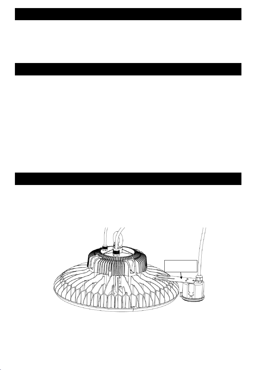
• Remove screws from sensor mounting bracket holes and line up bracket and screw into place
(See Fig 1)
• Attach sensor to bracket via 3 screws
• Wire the sensor as per Fig 2 ensuring correct polarity is observed
HBLS
Theseinstructionsshouldbereadcarefullyandretainedafterinstallationbytheenduserforfuturereferenceand
maintenance.
Theseinstructionsshouldbeusedtoaidinstallationofthefollowingproduct:
HBLS(sensor)
SAFETY
• Installationofthissensorshouldonlybecarriedoutbyaqualifiedelectricianorcompetentpersontothe
latestBuildingandcurrentIEEWiringRegulations(BS7671)
• Pleaseisolatemainspriortoinstallation/maintenance
• Checkthetotalloadonthecircuit(includingwhenthisluminaireisfitted)doesnotexceedtheratingofthe
circuitcable,fuseorcircuitbreaker
• PleasenotetheIP(IngressofProtection)ratingofthissensorwhendecidingthelocationforinstallation
• ThisproductisClassIIdoubleinsulated
• ThisproductisIP65rated
• Thedimmingprotocolusedonthissensoris1-10V
INSTALLATIONOFSENSOR
• Providepowertotherequiredpointofinstallation.SuitableIPratedjunctionboxesshouldbeusedwhere
required
• Werecommendaninstallationheightofupto15mmax
• Removescrewsfromsensormountingbracketholesandlineupbracketandscrewintoplace(SeeFig1)
• Attachsensortobracketvia3screws
• WirethesensorasperFig2ensuringcorrectpolarityisobserved


