MLT FS-16-25 User manual

Automated Slide Stainer FS-16-25
Instruction for Use
Read carefully before working with the stainer
Always keep this Instructions for Use near the stainer
V1.1 English – 10.02.2021
Dubna

1
Revision history
Revision Effective date Change Written by
1.0 22.01.2021 Draft Bezrukov A.V.
1.1 10.02.2021 For CE marking Kutepov M.V.
Bezrukov A.V.

2
FORBIDDEN TO OPERATE THE STAINER WITHOUT PRIOR READING THE
INSTRUCTION FOR USE.
CAUTION! ALWAYS KEEP THIS INSTRUCTION FOR USE NEAR THE
STAINER.
MLT LLC reserves the right to change technical specifications as well as
manufacturing processes without prior notice. Only this way is it possible to
continuously improve the technology and manufacturing techniques. The information
on important changes is added to the technical file of the device and is published on
the manufacturer’s website www.mlt.ru.
The latest technological programs, tutorial video materials, as well as
supplementary documents for the device FS-16-25 are available on the website
www.fastainer.com, section http://fastainer.com/resources.
Any copyrights of this document are retained by MLT LLC.
Any reproduction of text and illustrations of this document requires prior
permission in writing by MLT LLC.
For the device serial number and year of manufacture, please refer to the
nameplate at the back of the device.
MLT Limited Liability Company
Tehnologicheskaya street 7, 141981, Moscow Region, Dubna, Russia
Tel: +7 (495) 287 81 00; e-mail: [email protected], [email protected];
web: www.mlt.ru, www.fastainer.com

3
Table of contents
1 Important information ........................................................................................................ 5
1.1 Used symbols and indications .................................................................................... 5
1.1.1 Warning words. .................................................................................................... 5
1.1.2 Symbols. .............................................................................................................. 6
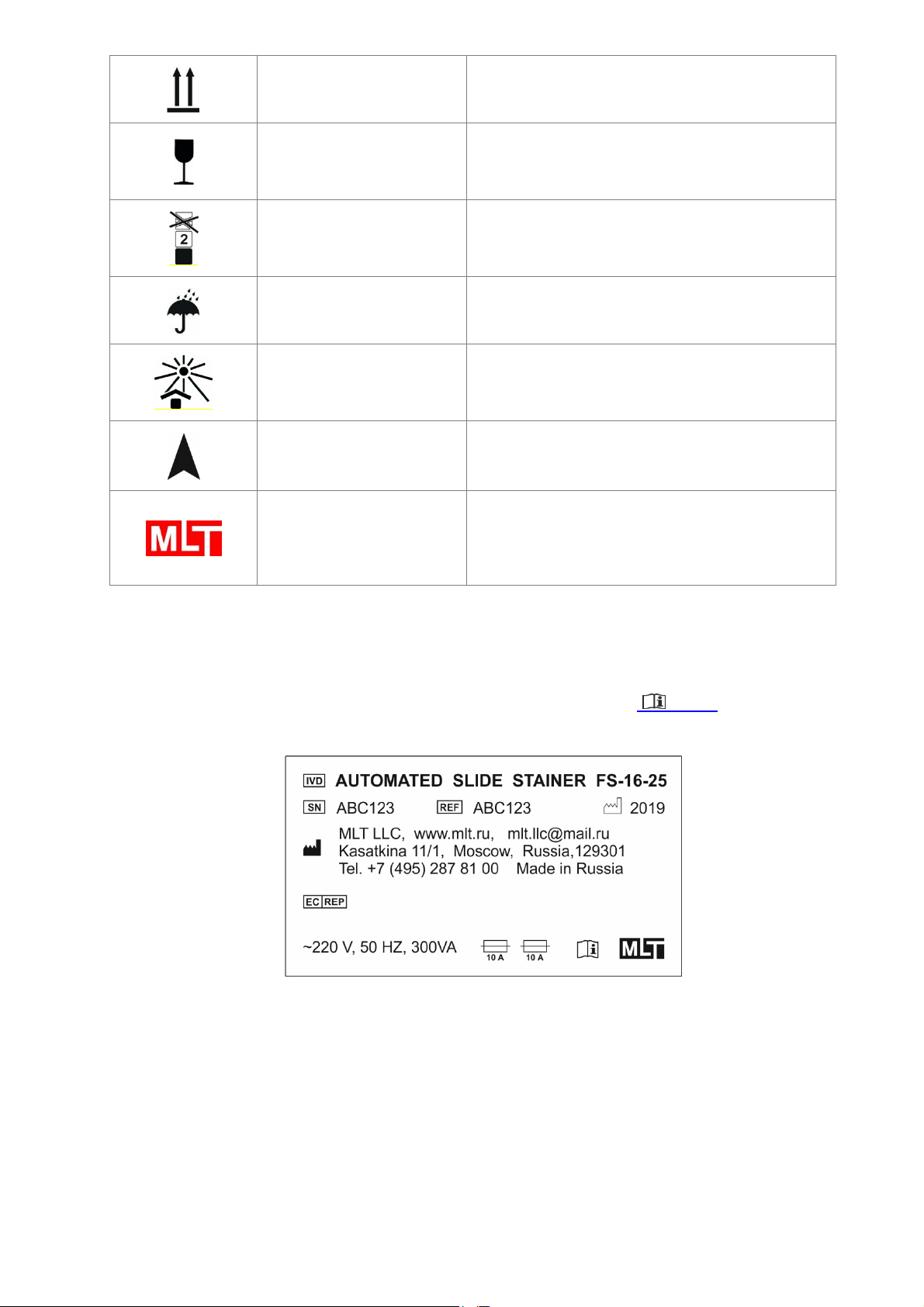
1.1.3 Stainer label. ........................................................................................................ 7
1.1.4 Designation of menu sections, touch screen buttons, and operational actions. ... 8
1.2 Intended use ............................................................................................................... 9
1.3 Compatibility with reagents and accessories of other manufacturers ......................... 9
1.4 Qualification of personnel ........................................................................................... 9
2 Safety ............................................................................................................................. 10
2.1 General safety statements ....................................................................................... 10
2.2 Special safety statements ........................................................................................ 10
3. General characteristics .................................................................................................. 12
3.1 Description of Stainer ............................................................................................... 12
3.1.1 Construction of Stainer. ......................................................................................... 12
3.1.2 Accessories: troughs and racks. ........................................................................ 15
3.1.4 Micro SD card and micro SD card slot. ............................................................. 16
3.1.5 Working principle of Stainer. .............................................................................. 16
3.2 Technical data .......................................................................................................... 18
3.3 Environmental conditions ......................................................................................... 18
3.4 Delivery set ............................................................................................................... 19
4. Unpacking and installation of Stainer ............................................................................ 20
4.1 Site requirements ..................................................................................................... 20
4.2 Unpacking of Stainer ................................................................................................ 20
4.3 Connection of Stainer ............................................................................................... 22
5. Operation and control of functioning .............................................................................. 25
5.1 Main menu, menu structure ...................................................................................... 25
5.2 Menu section «TECHNIQUES»: programming of new techniques, editing of
parameters of previously downloaded techniques.......................................................... 26
5.3 Menu section «CONFIGURATION»: programming and control of the configuration,
performing of service functions....................................................................................... 32
5.3.1 Setting the interval of the introduction of racks into the process. ....................... 36
5.3.2 Menu section «SERVICE». Performing of service functions. ............................. 38
5.4 Menu section «PROCESS»: loading and unloading of racks. Processing of racks
with slides according to a given technological program .................................................. 40

4
5.4.1 Automated system for loading and unloading racks through the gateway ................ 40
5.4.2 Automated loading and unloading of racks through the gateway. ...................... 41
5.4.3 Automated loading and unloading of racks through the manipulator. ................ 42
5.4.2 Loading of racks during the performance of a technological program. ............... 44
5.5 Status screen during a technological process ....................................................... 45
6. Preparing for operation .................................................................................................. 48
6.1 Switching on ............................................................................................................. 48
6.2 Check of working capacity ........................................................................................ 48
6.2.1 Positioning test. .................................................................................................. 48
7. Work sequence .............................................................................................................. 51
7.1 Before operation ....................................................................................................... 51
7.2 Switching on ............................................................................................................. 51
8 Cleaning, disinfection, and maintenance ........................................................................ 53
8.1 Cleaning and disinfection of outer surfaces and the working chamber ..................... 53
8.2 Flow-through trough and drain system ..................................................................... 53
8.3 Troughs for reagents ................................................................................................ 53
8.4 Racks ....................................................................................................................... 53
8.5 Mesh water filter ....................................................................................................... 54
8.6 Air filter ..................................................................................................................... 54
9 Troubleshooting .............................................................................................................. 55
10 Decommissioning and recycling ................................................................................... 55
11 Confirmation of performed sanitary treatment .............................................................. 56
APPENDIX A. Instruction on fire safety measures ............................................................ 57
1 General provisions ...................................................................................................... 57
2 Requirements to the room ........................................................................................... 57
3 Safety measures when handling HFL and CL ............................................................. 57
4 Actions in case of fire .................................................................................................. 58
APPENDIX B. List of reagents FS-16-25* ........................................................................ 59
APPENDIX С. Example of developing the <DEMO> program ........................................... 59
Protocol of the <DEMO> program and its configuration ................................................. 60
Listing of the <DEMO> program and its configuration .................................................... 61
APPENDIX D Template for developing a new technological program ............................ 62
( The file with the Template is available at fastainer.com/resources ) ........................... 62
APPENDIX E Recommended protocol of H&E (histology) ............................................. 63
APPENDIX F. List of adopted terms and abbreviations .............................................. 64
APPENDIX G. «FASTAINER FIRMWARE EDITOR» PC SOFTWARE ........................... 66

5
1 Important information
General
This instruction for use includes important information related to the operating safety
and maintenance of the automated slide stainer FS-16-25 (further – Stainer). The instruction
for use is an important part of the product. It must be read carefully and completely before
setup and prior use of the Stainer and must be kept near the device at all times. If additional
requirements on accident prevention and environmental protection exist in the country of
operation, the instruction for use must be supplemented by appropriate instructions to
ensure compliance with such requirements.
Diagnosis should not be made only with staining results obtained with Stainer.
FORBIDDEN TO OPERATE THE STAINER WITHOUT PRIOR READING THE
INSTRUCTION FOR USE. First of all, be sure to carefully read and comply with chapter 2
“Safety”.
1.1 Used symbols and indications
1.1.1 Warning words.
Warning words: CAUTION!, FORBIDDEN are marked by capital letters and white
font color on black background. The text following the warning words is marked by capital
letters.
When several warnings are standing together, they are grouped in such a way that
the first ones refer to the safety of personnel.
Symbol Description
CAUTION!
The CAUTION! sign is used to attract the attention of personnel to
the ways and methods that should be strictly followed to avoid
mistakes in operation and repair of the Stainer, or when extra
carefulness is vital in handling the device or materials.
FORBIDDEN
The FORBIDDEN sign is used to indicate that a violation of the
defined limitations or nonobservance of the requirements, referring
to the usage of materials, as well as to the ways and methods of
handling the Stainer, may lead to violation of safety measures.

6
1.1.2 Symbols.
Symbol Name of the symbol Location, designation
Warning, danger
Lid of the Stainer. A warning about handling of toxic
and corrosive reagents, about the necessity to use
protective equipment.
Fire hazard Lid of the Stainer. A warning about the handling of
highly flammable liquids.
Biological hazard
Lid of the Stainer. A warning about handling of
hazardous biological samples, about the necessity
to use protective equipment.
Warning, danger
Rear panel of the Stainer beside the fuses’ lid. A
warning about the risk of setting the device on fire if
fuses with the wrong rating are used.
Warning, danger
Manipulator housing in the center of the working
chamber. A warning about the risk of injuries by
moving manipulator.
Hot surface
Inside the working chamber beside the drying
station. The symbol indicate a risk of burns because
of hot surfaces. Do not touch these parts. The
symbol shown here indicates areas where the
temperature may exceed 60°C
OFF Right panel of the control unit, power switch.
ON Right panel of the control unit, power switch.
Device for IN VITRO
diagnostics
Instruction for use, label on the rear panel of the
Stainer.
Serial number Instruction for use, label on the rear panel of the
Stainer.
Catalog number Instruction for use, label on the rear panel of the
Stainer.
Manufacturer Instruction for use, label on the rear panel of the
Stainer.
Manufacture date Instruction for use, label on the rear panel of the
Stainer.
Authorized representative
in the EU
Instruction for use l, label on the rear panel of the
Stainer.
Fuse rating Instruction for use, label on the rear panel of the
Stainer.
Refer to the instruction for
use Operational documentation.

7
UP Labels on the packing box of the Stainer, indicating
the correct position of the cargo.
Fragile. Caution. Fragility of
the cargo. Careful handling
of the cargo.
Labels on the packing box of the Stainer, stating
the necessity of careful handling of fragile cargo.
Limit on the number of tiers
in a stack.
Labels on the packing box of the Stainer. The limit
number of tiers when piling in a stack – 2 (Two).
Protect from moisture. Labels on the packing box of the Stainer, stating
the necessity to protect the cargo from moisture.
Protect from sun radiation.
Labels on the packing box of the Stainer, stating
the necessity to protect the cargo from sun
radiation.
Open here Labels on the packing box of the Stainer.
Operational documentation.
MLT LLC logo
Instruction for use, label on the rear panel of the
Stainer, labels on the packing box of the device. A
stylized image of the manufacturing company’s
name.
1.1.3 Stainer label.
The label containing the Stainer’s name, its serial number, the year of manufacture
and other information is situated at the rear panel of the device. ( 3.1.1)
Figure 1. The appearance of the Stainer label.

8
1.1.4 Designation of menu sections, touch screen buttons, and operational
actions.
Menu sections are designated with capital letters between double angle quotation
marks, e.g., «PROCESS», «SERVICE», «CONFIGURATION», etc.
Touch screen buttons are designated in the text as inscriptions in capital letters
placed in a frame, e.g., ENTER, YES, STOP. The symbol is designated a cyclic
switching of buttons.
Use of touch screen buttons with icons.
◄► – to switch between two screens with a list of names of technological programs.
▼, ▲ – to switch between screens with the same application (6 screens with a list of
reagents, screens with listings of a program).
– to erase the last entered symbol (digit).
Messages on the screen are designated with capital letters between single angle
quotation marks, e.g., <PROGRAM WAS CHANGED>, <SAVE THE CHANGES?>.

9
1.2 Intended use
The automated slide stainer FS-16-25 is a device for IN VITRO diagnostics. The
device is designated for the staining of biological preparations on slides. The primary
intended use is histology (particularly – H&E technique) and cytology (particularly –
Papanicolaou stain, for conventional and LBC preparations). The device also can be
successfully used for preparation staining in hematology, microbiology, parasitology.
FORBIDDEN TO USE THE STAINER FOR ANY PURPOSE OTHER THAN THE
DESIGNATED ONE.
The violation of this requirement may result in accidents, injuries, damages to the
device. The designated use comprises observance of all requirements of the instruction for
use, including observance of the control and maintenance intervals, a routine check of expiry
dates, and quality of reagents. The Stainer performs a chosen technological program
automatically. The manufacturer is not liable to respond if a mistake in programming or
during operation is made, inappropriate reagents are used, the reagents are placed
inappropriately, a program is started with closed lids of troughs, etc.
1.3 Compatibility with reagents and accessories of other manufacturers
The Stainer is an open system. The programs, supplied with the Stainer, may need
corrections of parameters or changes in programs if used with reagents of other
manufacturers. In most cases, a correction of the duration of technological treatments might
be needed. Staining kits manufactured by MLT LLC are supplied with an operational
instruction with a recommended technological program. The responsibility for independently
compiled programs, for reagents purchased from other manufacturers, or for self-
manufactured reagents is born by the end-user.
FORBIDDEN TO USE ACCESSORIES AND SPARE PARTS, NOT AUTHORIZED
BY THE MANUFACTURER.
1.4 Qualification of personnel
The FS-16-25 may be operated only by trained laboratory specialists – doctors and
lab technicians. All laboratory personnel designated to operate the Stainer must read this
instruction for use with all appendices carefully and must be familiar with all technical
features of the Stainer before attempting to operate it.
FORBIDDEN TO OPERATE THE STAINER UNLESS THE PERSONNEL HAS
COMPLETED A SAFETY TRAINING, AND UNLESS READ CAREFULLY THIS
INSTRUCTION FOR USE WITH ALL APPENDICES.

10
2 Safety
2.1 General safety statements
This Stainer has been developed, manufactured, and tested under safety
requirements for electrical laboratory devices. To maintain a safe technical state of the
Stainer, the operator must observe all requirements of this instruction for use. If the
instructions are not followed, then the protection provided by the device may be impaired.
All users must read and understand the Instruction for Use and only operate the Stainer in
accordance with this instructions. A warning is given in the document if there is a danger of
personal injury or damage to samples or equipment. If additional requirements on accident
prevention and environmental protection exist in the country of operation, the instruction for
use must be supplemented by appropriate instructions to ensure compliance with such
requirements.
2.2 Special safety statements
The Stainer weighs 22 kg. When packed, two boxes with accessories are placed
inside the working chamber, so that the total weight amounts to about 25 kg.
FORBIDDEN TO UNPACK AND TO CARRY AN UNPACKED STAINER ALONE.
FORBIDDEN TO RAISE AND CARRY THE DEVICE, HOLDING IT BY THE UPPER
PANEL (20) ( Fig.4, Fig. 6).
Toxic and corrosive reagents, highly flammable liquids, as well as potentially
hazardous biological preparations may be used during operation.
Refer to your own laboratory procedures and material safety data sheets (MSDSs)
when using reagents. Material safety data sheets can be obtained from the supplier of the
chemicals. They are also available on the Internet: http://www.msdsonline.com.
FORBIDDEN TO HANDLE REAGENTS AND BIOLOGICAL PREPARATIONS
WITHOUT APPROPRIATE PROTECTIVE EQUIPMENT: LAB COAT, GLOVES,
GOGGLES.
FORBIDDEN TO HAVE MEALS IN THE ROOM, WHERE THE STAINER IS
INSTALLED.
The Stainer is connected to the power supply net ~ 220 V with a cable with protective
grounding. The socket must also be grounded.
FORBIDDEN TO OPERATE THE STAINER, IF IT IS NOT CONNECTED TO
GROUNDING.
Toxic and corrosive reagents may be used during the operation, so the device must
be either connected to the laboratory exhaust ventilation system or installed in an exhaust
hood.

11
FORBIDDEN TO OPERATE THE STAINER, IF IT IS NOT CONNECTED TO
VENTILATION OR BEYOND EXHAUST HOOD.
Highly flammable liquids, such as spirits, spirit-based dyes, xylene or xylene
substitutes may be used during an operation.
FORBIDDEN TO INSTALL THE STAINER IN DIRECT VICINITY OF A FLAME OR
IGNITABLE SPARKS.
FORBIDDEN TO INSTALL THE STAINER IN A ROOM WITH NO FIRE
EXTINGUISHING MEDIA, SUCH AS CO2 OR HALON FIRE EXTINGUISHER.
A standard instruction on fire safety measures given in Appendix A.
FORBIDDEN TO DISMANTLE THE STAINER: ELECTRIC SHOCK MAY RESULT!
ANY UNAUTHORIZED DISMANTLING OF THE STAINER RENDERS THE WARRANTY
INVALID.
Only authorized and qualified service personnel may repair the instrument and
access the instrument's internal components.
Do not modify the instrument – if unauthorised modifications are carried out, the
instrument may be made unsafe and the warranty may be invalidated.

12
3. General characteristics
3.1 Description of Stainer
3.1.1 Construction of Stainer.
The Stainer consists of a technological unit (5) with a working chamber and a lid (1)
and a control unit (3) with a touch-screen (4).
Figure 2. Front view of the Stainer.
1 – transparent lid; 2 – uploading gateway; 3 – control unit; 4 touch-screen; 5 – technological
unit with a working chamber, 6 – handle of the lid.

13
Figure 3. Rearview of the Stainer.
1 – transparent lid; 7 – exhaust water outlet; 8 – exhaust ventilation grid with an outlet* 9 –
tap water inlet; 10 – Stainer label with a serial number, manufacturing year; 11 – power
supply inlet**;12 – protective cover for 10 A electric fuses; 13 screw-type feet;
* An inflow ventilation inlet, protected by a removable lid and a filter, is situated on the bottom
of the Stainer.
**The power switch is placed on the left side panel of Stainer.

14
Figure 4. Top view of the Stainer, working chamber of the technological unit.
14 – drying station; 15 – arm of manipulator; 16 – trough with a rack inside; 17 – rack with
slides; 18 – handle of rack; 19 – manipulator housing; 20 – upper panel of Stainer; 21 – flow-
through trough; 22 – drainage hole of flow-through station; 23 – water level sensor; 24 –
grab of manipulator; 25 – positioning disk; 26 – index plate of stations numeration; 27 – tray
of gateway (parking station №9).

15
3.1.2 Accessories: troughs and racks.
The Stainer is supplied with RV-25 racks for 25 slides.
Figure 5. Stainless steel rack RV-25 with slides.
17 – rack; 18 – handle of the rack
The Stainer is supplied with two types of troughs:
TV-25-POM – a polyoxymethylene trough (color: grey) for RV-25 racks;
recommended when handling xylene; substitutes of xylene; aqueous solutions; and
solution with pH≥7.
Figure 6. Accessories for the Stainer.
16 – TV-25-POM trough; 17 – rack; 18 – handle of the rack; 28 – the lid of the trough; 29 –
positioning element of the trough.

16
TV-25-PP – a polypropylene trough (color: either white or natural half-
transparent) for RV-25 racks; recommended when handling aqueous solutions; spirits; and
acetone.
Recommended volume of liquid in troughs:
when there are 25 slides loaded into the rack – 210 ± 10 ml.
when there are 12 slides loaded into the rack – 220 ± 10 ml.
when there are 5 slides loaded into the rack – 230 ± 10 ml.
3.1.4 Micro SD card and micro SD card slot.
The Stainer is supplied with micro SD card, and the micro SD card slot. The memory
card is used to store microprocessor firmware data. The firmware can be updated or edited
using the software for PC "Fastainer Firmware Editor" (APPENDIX F).
The micro SD card slot is placed inside the control unit (3). All manipulations with the
micro SD card are allowed only for engineering personnel who have been instructed by the
manufacturer. The use of the "Fastainer Firmware Editor" software for the development of
technological programs is allowed for any laboratory personnel.
3.1.5 Working principle of Stainer.
The principle of the staining process is the sequential programmed movement of
racks with slides from station to station where technological operations are carried out.
The working chamber of Stainer is covered with a transparent lid and has compulsory
ventilation, which ensures safety in handling toxic reagents.
The Stainer are equipped with the following types of stations:
● one station with a flow-through trough (tap water);
● one station for drying or heating with warm air flow;
● one station for automated loading and unloading of racks;
● combined stations – either for placement of troughs with liquid reagents, or for placement
of racks with slides, what makes it possible to create an optimum configuration of a device
for each staining technique and even for each laboratory.
The device stains slides using a group method. The slides are put into a rack. The
racks are loaded into the working chamber and arranged at parking stations
automatically with the help of a manipulator (15). When the loading of racks is complete,
the Stainer starts to perform a technological program: the manipulator transfers the racks
with slides from station to station, where there are troughs with reagents, and where

17
technological operations are carried out (fixation, staining, washing, drying, blotting and so
on).
Operation duration, reagent, and station, in which the operation is performed, are
programmable and changeable. Control and programming are performed with a color touch-
screen display. Programming functions include not only the consequence and duration of
technological operations but also their parameters and modes. For instance, a technological
operation can be performed in a number of ways: immersion into the reagent, immersion
with a programmed period of activation, repeated dipping of slides into the reagent (can
accelerate the speed of procession).
When processing of a rack is complete, it goes back to the initial station, where it
has been loaded in the beginning*— the Stainer signals about the completion of
processing of each rack and all loaded racks. Unloading of racks is performed
automatically with the help of the manipulator.
The mechanics of Stainer is unique in simplicity and reliability. The racks with slides
rotate not only in a horizontal plane but also up and down. The rising of a rack from reagent
is accompanied with inclining and vibration, which facilitates the draining of excess liquid
from slides and the rack. Thus, the transfer of reagents between troughs is very low. The
manipulator’s mechanism is designed in such a way that a rack gets firmly fixed in its grab,
making it possible to carry out high-speed movements (during dipping, shaking, transfer
from station to station, etc.). The option to program the duration of delay of a rack above the
trough (‘draining time’) lets excessive reagent flow off. Programming the interval for the new
rack processing launch makes it possible to configure programs with a parallel procession
of several racks. To multiply performance, there is a possibility to install several troughs with
the reagent that is used for a most time-consuming operation.
Thus, the Stainer offers a good number of opportunities to make the process of
staining FAST, versatile, and efficient despite their compact size.
*There is one exception of this rule: the reagent <XYLENE-E>, assigned to a station,
where the last operation of a program is performed, possess particular properties. When
this reagent is assigned, the processed rack with slides remains at the last station in
<XYLENE-E> and does not return to the parking station.

18
3.2 Technical data
Number of combined stations 13
Number of upload-unload stations (gateway) 1
Number of drying stations 1
Number of washing stations (with a flow-through trough) 1
Size of slides* 76 26 х 1,0 mm
Stained part of a slide ~ 26 × 55 mm
Capacity of RV-25 racks 25
Heating modes of the drying station strong/weak
Ventilation of the working chamber forced
Graphic touch screen (control) 480 272 pixels
Number of staining programs, supplied with the Stainer 1
Max. number of staining programs 32
Max. number of steps in a program 30
Max. number of programmed reagents’ names 96
Power supply ~ 220 В 10%, 50 Hz
Power consumption, no more than 300 V*А
Dimensions 600х550х370 mm
Weight 22 kg
3.3 Environmental conditions
Operational temperature: from 15 to 35 °C
Operational relative humidity: 80 %, non-condensing
Storage temperature: from -40 to +50 °C
Storage relative humidity: 80 %, non-condensing
Transportation temperature: from -40 °C to +50 °C
Transportation relative humidity: 80 %, non-condensing
* It is possible to order racks for slides of other sizes.

19
3.4 Delivery set
A standard delivery set includes:
Device Product code Quantity
Automated slide stainer FS -16-25 266012.006 1
Accessories
RV-25 rack for slides (for 25 slides) 06.01.00 2
TV-25-PP trough for reagents with a lid 06.06.00 10
TV-25-POM trough for reagents with stainless steel lid 06.06.00-01 2
Blotter 07.10.00 1
Kit for tap water connection,
including: 05.70.00 1
- Нose for water connection 05.70.01 1
- Drain hose 05.70.02 1
Power cord 05.50.00 1
Fuse 05.51.00 2
Instruction for use 266012.007 IU 1
Table of contents
Other MLT Laboratory Equipment manuals