MLT PLYS 15 User manual

Épaisseur de revêtements
de votre bande avant décorticage
mm 3 + 1 4 + 1,5 5 + 1,5 4 + 2 5 + 3 6 + 2 6 + 3 8 + 3
inch 1/8’’ +
1/32’’
5/32’’ +
1/16’’
3/16’’ +
1/16’’
5/32’’ +
1/16’’
3/16’’ +
1/8’’
1/4’’ +
1/16’’
1/4’’ +
1/8’’
5/16’’ +
1/8’’
Lame de décorticage (en mm) 3,5 4,5 4,5 4,5 2,5 4,5 3,5 6,5 2,5 6,5 3,5 8,5 3,5
SUPER-SCREW®
Evolution
Bande EP ou PP* Entretoise Dimensions des vis
N/mm PIW
35 250/2 253/3
200
Taille unique
Entretoise
SUPER-SCREW®
EVOLUTION
315/2 315/3
40 400/2 400/3 228
63
500/3 500/4
360630/2 630/3
630/4 630/5
65
500/3 500/4
360630/2 630/3
630/4 630/5
USER MANUAL
PLY SEPARATOR
MLT PLYS 15

Index:
CE Declaration of conformity:...................................................................................................................................................................................1
Electrical connection to the grid:.............................................................................................................................................................................4
Description:...................................................................................................................................................................................................................4
Characteristics:............................................................................................................................................................................................................4
User instructions:........................................................................................................................................................................................................5
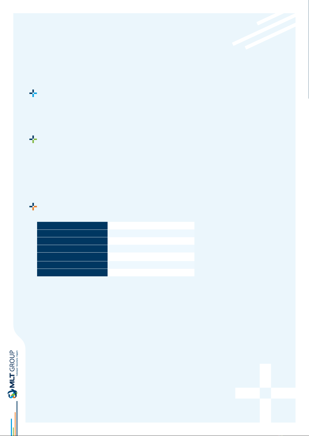
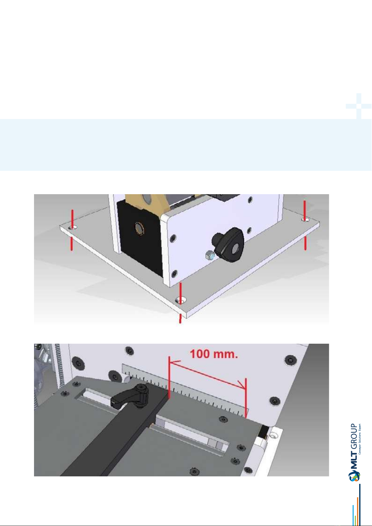
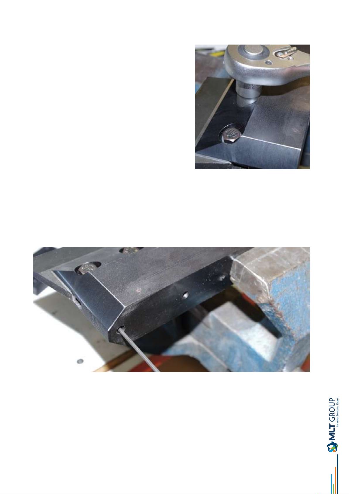
Changing and adjusting the blade:..........................................................................................................................................................................6
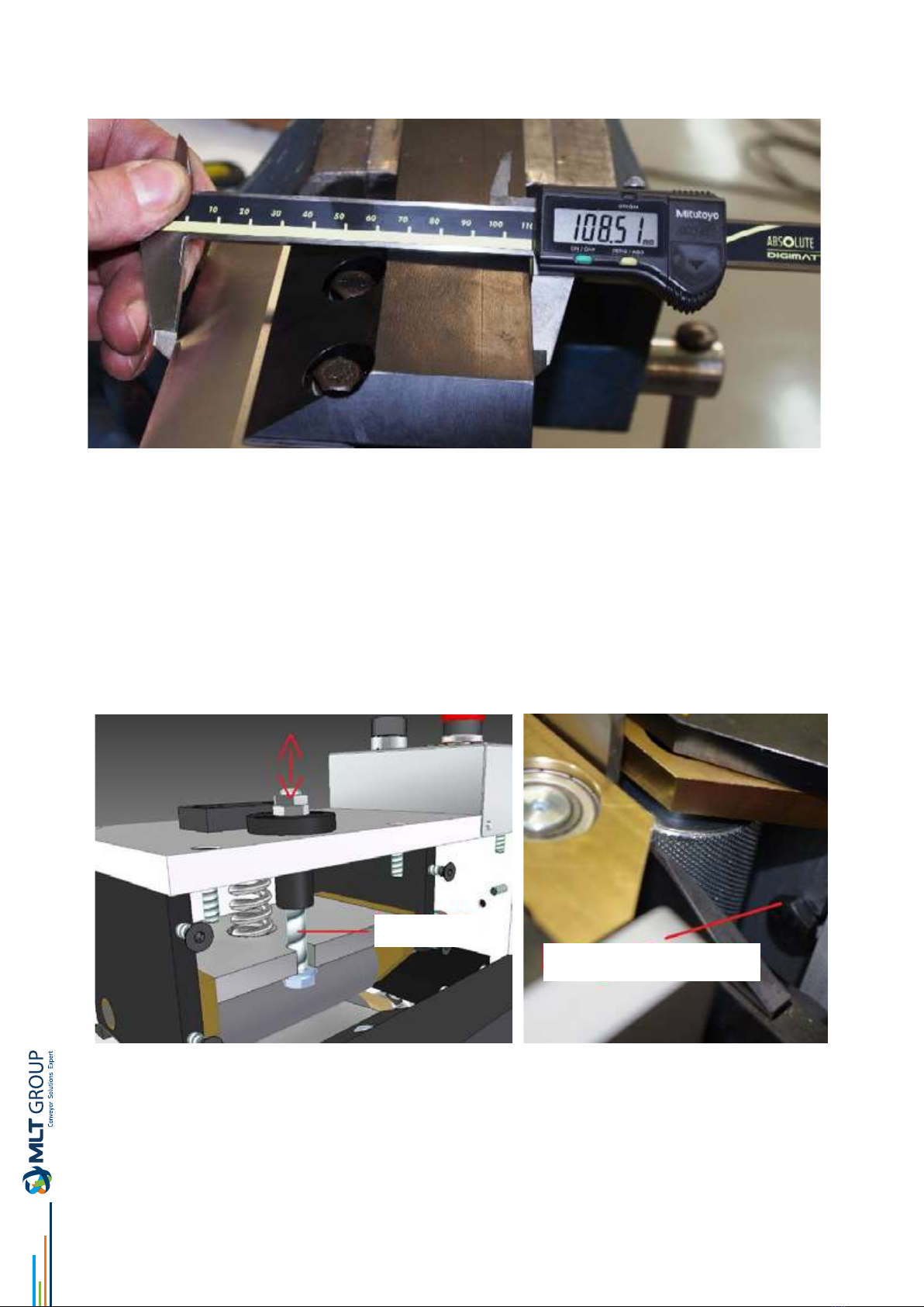
Stroke adjustment of rollers:...................................................................................................................................................................................8
Electrical diagram:....................................................................................................................................................................................................10
Parts list:.....................................................................................................................................................................................................................10

DECLARATION « CE» DE CONFORMITE
We, undersigned,
MLT ZI du Clos Marquet - Rue Michel Rondet - CS 70059 -
42 200 Saint-Chamond, France
The person(s) authorised to compile the technical documentation :
- Gilles FURNON : Product Manager, MLT
declare that the new machine subject to self-certication designated below :
Inspired by the directives of the Ocial Journal of the European Communities: 2006/42/CE
Complies with the design and construction specications of the European Standards on General Machine Safety:
• EN ISO 12100-1
• EN ISO 12100-2
• EN 60204-1
• EN ISO 13250
• EN ISO 13857
• EN ISO 14121-1
Model: PS-15
Serial Number: 13903
Year of manufacture: 2018

Electrical connection
Connect the equipment to a 230 v or 400 v three-phase depending on the voltage shown on the technical specications
plate, and its corresponding earth connection, without taking into consideration the direction of the motor rotation. This
equipment has a rotation selector.
Description
The ply separator is activated by a reducer motor and drive sha, with manually controlled height adjustment by way of
eccentrics.
Support table with adjustable cutting width guide.
Pinch roller closure activated by compression spring.
Characteristics:
Dimensions 481 × 402 × 370 mm (l × w × h)
Weight 31 Kg
Blade width 100 mm
Max. cutting width 160 mm
Max. thickness 20 mm
Voltage 1x220V
Power 0.37 Kw

NOTE
Although the initial cut is 100 mm, keep in mind that depending on the toughness of the material used, various passes must
be done in order to obtain the desired nal width.
WARNING
THIS DEVICE INVOLVES THE HAZARD OF HANDS BEING TRAPPED AND CUT BY THE PINCH ROLLERS. THE USER
SHOULD EXERCISE GREAT CARE AND PRECAUTION IN THE MATERIAL ENTRY ZONE, AVOIDING THE PLACEMENT OF
HANDS IN THIS ZONE.
Once the equipment is connected to the mains, it must be xed to a table or support through the four holes in its base, to
avoid overturning or falls.
Always adjust the cutting guide to less than 100 mm, before introducing the material.
User
instructions

The cutting thickness is adjusted by turning the height regulation control found on the right hand side.
Perform a test on a corner of the belt, or on a scrap piece of the same material, to see if the height adjustment and pressure
is correct.
Separate the belt ply belt applying one or more passes, depending on the hardness or substance of the material being
worked on, and depending on the adjustment of the table’s opening guide.
WARNING
WHEN CHANGING THE BLADE, DISCONNECT THE POWER CORD FROM THE MAINS, TO AVOID ACCIDENTS.
Changing and adjusting the blade
Take o the blade support by removing the two M10 Allen screws using an 8 mm Allen key.

Also, use a 5mm. Allen key to the arm.
Once the blade arm assembly has been taken o, loosen the two M8 bolts that x the blade to the support, with a 13mm key.
Remove the old blade and insert the new one, up to the limit set by the two adjustment screws in the rear. These two limiting
screws in the rear determine the proximity of the blade to the pinch rollers.

Adjust this measure to 108.5 mm.
Aer changing the blade, reset the support to its original position by rmly tightening the two M8 Allen screws.
Set adjustment of rollers:
NOTE:
The incorrect stroke adjustment of the rollers may cause the blade’s cutting edge to break if they are too close, or on the
contrary, may cause poor traction when using thin materials.
To adjust the height of the upper roller, adjust the M10 screw that is on the upper cover.
Screw M10
Key 17mm

To adjust the height of the lower roller, adjust the M8 screw that is on the right hand side cover, next to the height regulation
control
WARNING
ATTENTION: Although safety systems are present, due to the function of the equipment, there is a high risk of
trapping and cutting in the open zone.
• Check the voltage of the equipment before connecting to the mains.
• Do not use the equipment in damp environments or with a wet oor.
• Always work with the equipment fastened to a stable and sturdy base.
• Avoid the use and operation of this equipment by inexperienced or unqualied sta.

hotline pre-registration
www.mlt-lacing.com/mlt-hotline
HOTLINE MLT service
Our MLT representatives will assist you remotely and in pictures
The HOTLINE MLT service is at your disposal to assist
you live in the resolution of any problems you may
encounter:
belt rupture, a rip or any other problem on your
conveyor belt, we can help you free of charge, remotely
and in pictures.
Our teams are available to answer your questions in 10
languages!
Register online so that one of our representatives
can contact you and help you as soon as possible:
www.mlt-lacing.com/mlt-hotline
This manual suits for next models
1
Table of contents
Other MLT Laboratory Equipment manuals
Popular Laboratory Equipment manuals by other brands

Oxford Instruments
Oxford Instruments X-MET8000 Series user manual

RWD
RWD RWD-MB-001-A user manual

Scientific Industries
Scientific Industries ROTATOR GENIE SI-2100 operating instructions

NSK
NSK Varios Combi Pro Operation manual

Boekel
Boekel InSlide Out 241000 operating instructions

ThermoFisher Scientific
ThermoFisher Scientific E-PAGE Gels Technical guide