MMF VM31 User manual

Instruction Manual
Manfred Weber
Metra Mess- und Frequenztechnik in Radebeul e.K.
Meissner Str. 58 - D- 1445 Radebeul
Tel. +49-351 836 2191 Fax +49-351 836 294
Email: [email protected] Internet: www.MMF.de
Human-
Vibration
Analyzer
VM31
(Valid from version xxx.016)

Published by:
Manfred Weber
Metra Mess- und Frequenztec nik in Radebeul e.K.
Meißner Str. 58
D-01445 Radebeul
Tel. +49-351-836 2191
Fax +49-351-836 2940
Email Info@MMF.de
Internet www.MMF.de
Note: T e latest version of t is manual can be found at ttp://www.mmf.de/prod-
uct_literature. tm
Specification subject to c ange.
© 2014 Manfred Weber Metra Mess- und Frequenztec nik in Radebeul e.K.
Full or partial reproduction subject to prior written approval.
Jan/ 19 #194

Contents
1. Purpose.................................................................................................................2
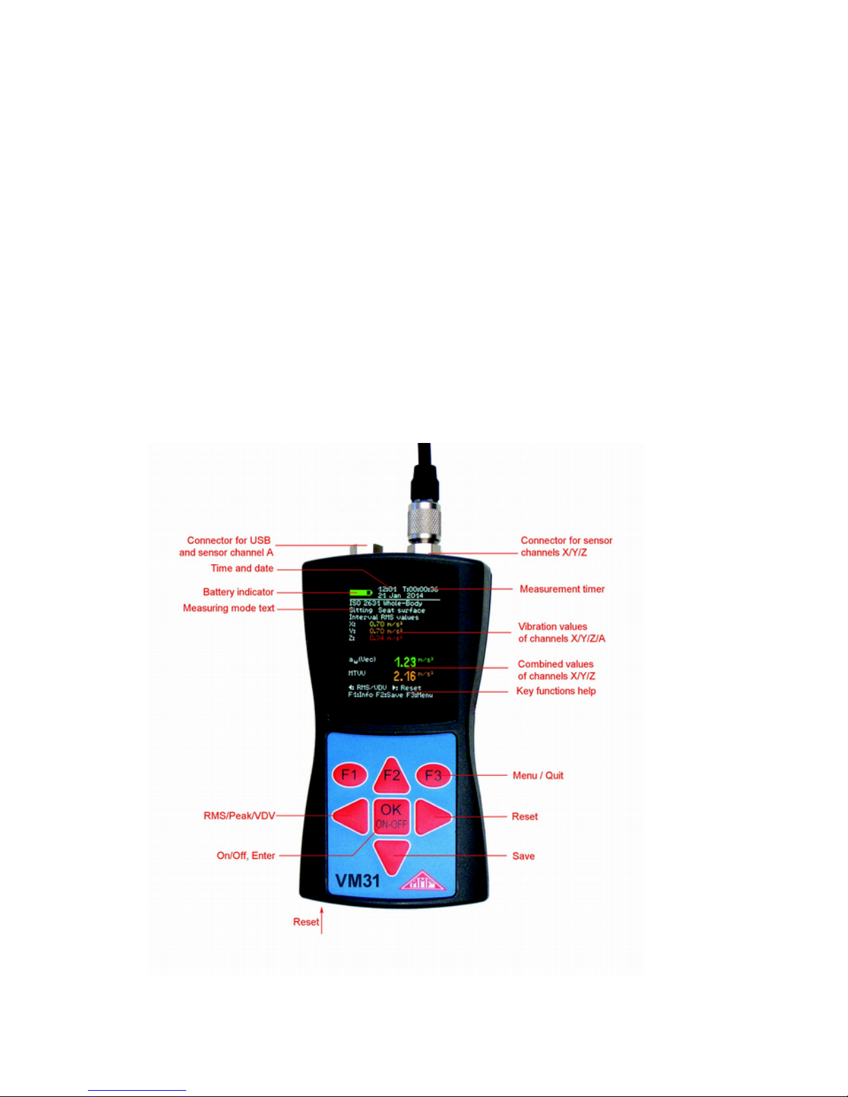
2. T e Device at a Glance.........................................................................................2
3. Fundamentals of Human Vibration Measurement................................................3
3.1. Introduction...................................................................................................3
3.2. EU Occupational Healt Directive 2002/44/EC............................................4
4. Human Vibration Measurement wit t e VM31...................................................7
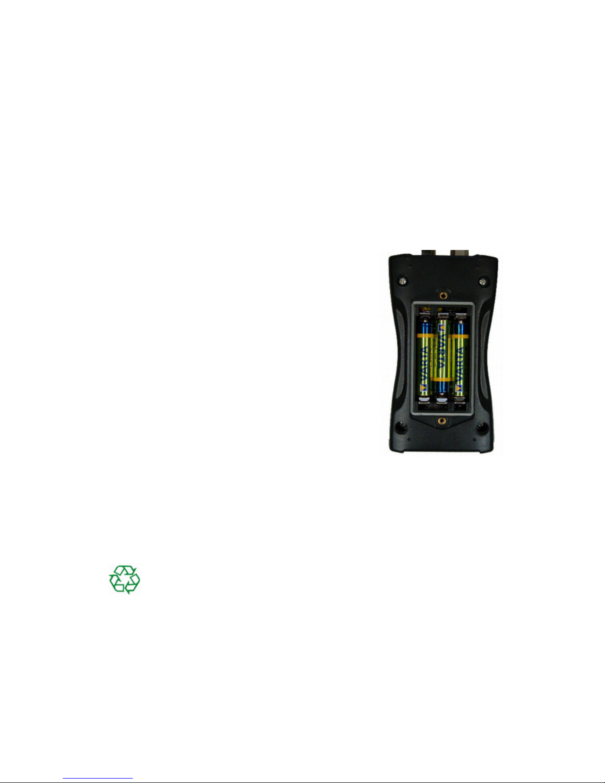
4.1. Batteries.........................................................................................................7
4.2. Switc ing on and Connecting t e Sensor......................................................8
4.3. Hand-Arm Measurement wit t e VM31......................................................9
4.3.1. Measuring Points for Hand-Arm Vibration............................................9
4.3.2. VM31 Settings.....................................................................................10
4.4. W ole-Body Measurement wit t e VM31.................................................12
4.4.1. Measuring Points for W ole-Body Vibration......................................12
4.4.2. VM31 Settings.....................................................................................13
4.4.2.1. W ole-Body Measurement wit RMS Values..............................13
4.4.2.2. W ole-Body Vibration Measurement wit VDV Values..............18
4.4.2.3. Seat Effective Amplitude Transmissibility (SEAT)......................18
5. General Vibration Measurement.........................................................................19
6. Data Logger........................................................................................................21
7. Frequency Analysis............................................................................................22
8. Data Memory......................................................................................................23
8.1. Measurement Data Memory........................................................................23
8.2. Logger Data Memory..................................................................................23
8.3. FFT Data Memory.......................................................................................24
9. Keypad Lock......................................................................................................24
10. Device Settings.................................................................................................24
10.1. Sensor Calibration.....................................................................................24
10.2. Time and Date...........................................................................................24
10.3. S ut-off Timer...........................................................................................25
10.4. Battery Type..............................................................................................25
10.5. Display Brig tness....................................................................................25
10.6. Menu Language.........................................................................................25
10.7. Default Settings.........................................................................................26
11. Reset Key..........................................................................................................26
12. Connection to a PC...........................................................................................26
13. Data Transfer to a PC........................................................................................27
13.1. Opening t e Excel File vm31.xlsm...........................................................27
13.2. Data Import to Excel.................................................................................28
13.3. Calculation of Vibration Exposure A(8) and VDV(8)...............................28
13.4. FFT Data Import to Excel.........................................................................29
14. Firmware Update..............................................................................................30
15. Calibration........................................................................................................32
16. Tec nical Data..................................................................................................33
Appendix: Warranty
Declaration of CE Conformity
1

Thank you for choosing a Metra Vibration Measurement device!
1. Purpose
T e VM31 as been developed, particularly, for t e measurement and analysis of
uman vibration. Ot er fields of application include mac ine condition monitoring,
building vibration measurement and quality control.
In combination wit a triaxial accelerometer, and-arm and w ole-body vibrations
can be measured in compliance wit ISO 5349, ISO 2631 and t e EU Directive
2002/44/EC. A fourt measuring c annel can be used, for example, for SEAT mea-
surements (seat effective acceleration transmissibility).
T e VM31 meets t e requirements for uman vibration meters in compliance wit
ISO 8041. In t e development of t e VM31 value was placed on simple operation
and compact design.
In addition to its application as uman vibration meter t e VM31 can also measure
mac ine vibration according to ISO 10816-1/2/3/5/6/7. Measuring ranges for accel-
eration, velocity and displacement are available.
2. The Devi e at a Glan e
2
Figure 1: Controls, connectors and display

3. Fundamentals of Human Vibration Measurement
3.1. Introdu tion
Vibrations affecting t e uman body are called uman vibration. T e main purpose
of measuring uman vibration is t e prevention of ealt risks and t e evaluation of
comfort, for example in ve icles.
Two categories are distinguis ed:
•Hand-Arm Vibrations, w ic are induced via t e ands into t e body. T ey
may cause, for example, circulatory disorder, bone, joint or muscle diseases.
•Whole-Body Vibrations, acting via t e buttocks, t e back and t e feet of a sit-
ting person, t e feet of a standing person or t e back and t e ead of a recumbent
person. Suc vibrations may cause backac e or damage to t e spinal column.
Bot types of uman vibration measurement are described in international standards:
•ISO 5349 - Measurement and evaluation of uman exposure to and-transmitted
vibration
•ISO 631 - Evaluation of uman exposure to w ole-body vibration
(also ASA/ANSI S3.18)
•ISO 8041 - Human response to vibration. Measuring Instrumentation
•ISO 866 - Hand- eld portable power tools - Measurement of vibrations at t e
andle
•ISO 0 83-5 - Guidelines for t e measurement, reporting and evaluation of vi-
bration wit regard to abitability on passenger and merc ant s ips
•ISO 10056 - Measurement and analysis of w ole-body vibration to w ic pas-
sengers and crew are exposed in railway ve icles
•ISO 103 6 - Laboratory met od for evaluating ve icle seat vibration
•ISO 89 7 - Hand- eld portable power tools - Test met ods for evaluation of vi-
bration emission
Practical advice for measurement and evaluation of uman vibration can be found in
VDI 057.
T e subject of uman vibration as gained particular importance in Europe since t e
directive 00 /44/EC came into effect. It specifies t e duties of employers wit re-
gard to workers protection.
3

3.2. EU O upational Health Dire tive 2002/44/EC
T e following text is an abstract of Directive 2002/44/EC of t e European Parlia-
ment and of t e Council dated June 25, 2002. T e complete text can be downloaded
from ttp://eur-lex.europa.eu/
T e directive specifies minimum requirements for t e protection of workers from
t e risks arising from vibrations. Manufacturers of mac ines and employers s ould
make adjustments regarding risks related to exposure to vibration.
T e directive lays down t e following limit values:
Hand-Arm, RMS Whole-Body, RMS Whole-Body, VDV
Exposure action
value
2.5 m/s² 0.5 m/s² 9.1 m/s1,75
Exposure limit 5 m/s² 1.15 m/s² 21 m/s1,75
Table 1: Limits to EU directive 2002/44/EC
Once t e exposure action value is exceeded, t e employer s all establis and im-
plement a program of tec nical and organizational measures intended to reduce to a
minimum exposure to mec anical vibration, taking into account in particular:
•Ot er working met ods t at require less exposure to mec anical vibration
•Appropriate work equipment of ergonomic design, producing t e least possible
vibration
•Provision of auxiliary equipment t at reduces t e risk of injuries, suc as protec-
tive gloves or special seats
•Appropriate maintenance programs for work equipment
•Design and layout of workplaces
•Adequate information and training to instruct workers to use work equipment
correctly and safely
•Limitation of t e duration and intensity of t e exposure
•Work sc edules wit adequate rest periods
•Provision of clot ing to protect workers from cold and damp
In any event, workers s all not be exposed above t e exposure limit value. If t is
s ould be t e case, t e employer s all take immediate action to reduce exposure be-
low t e exposure limit value.
T e met ods used may include sampling, w ic must be representative of t e per-
sonal exposure of a worker to t e mec anical vibration in question.
T e assessment of t e level of exposure to vibration is based on t e calculation of
daily exposure A(8) expressed as equivalent continuous acceleration over an eig t-
our work period. For t e determination of A(8) it is not necessary to measure over
eig t ours. It is sufficient to make s ort-term measurements during representative
work steps. T e results are normalized to eig t ours. Daily exposure is calculated
as follows:
4

A(8)=awe
√
Te
T0
Equation 1
w ere
A(8) is t e daily exposure
awe is t e energy equivalent mean value of t e frequency weig ted acceleration
during exposure, w ic means
- For Hand-Arm Vibration t e X/Y/Z vector sum of W frequency-
weig ted RMS values (Equation 2)
aw=
√
awx
2+awy
2+awz
2
Equation 2
- For Whole-Body Vibration t e ig est of t e t ree RMS values
awx, awy and awz wit t e following frequency and magnitude weig tings:
- X and Y wit weig ting filter Wd and weig ting factor 1.4
- Z wit weig ting filter Wk and weig ting factor 1.0
Te is t e total duration of exposure during one work day
T0is t e reference duration of 8 ours
Daily exposure may consist of several partial exposures wit different vibration
magnitudes. T is can be t e case if t ere are longer interruptions in t e work
process, if t e work equipment or its way of use is c anged. A partial exposure sec-
tion s ould ave a roug ly constant magnitude and less t an 10 % interruptions. Re-
sulting daily exposure is calculated as follows:
Hand-Arm Vibration:
A(8)=
√
1
T0
∑
i=1
n
awi
2Tei
Equation 3
w ere
A(8) is t e daily exposure
awi is t e energy equivalent mean value of t e W frequency weig ted accelera-
tion of partial exposure section i
n is t e number of partial exposure sections
Tei is t e duration of exposure i
T0is t e reference duration of 8 ours
Whole-Body Vibration:
Separate daily exposures need to be calculated for X/Y/Z. T e ig est value is used
for t e evaluation, i.e. compared wit t e limits of Table 1.
Ax(8)=
√
1
T0
∑
i=1
n
awxi
2Tei
Equation 4
5

Ay(8)=
√
1
T0
∑
i=1
n
awyi
2Tei
Equation 5
Az(8)=
√
1
T0
∑
i=1
n
awzi
2Tei
Equation 6
w ere
Ax/y/z(8) are t e daily exposures of directions X/Y/Z
awx/y/zi are t e energy equivalent mean values of t e frequency weig ted accelerations
in t e directions X/Y/Z during partial exposure section i wit t e following
frequency and magnitude weig tings:
- X and Y wit weig ting filter Wd and weig ting factor 1.4
- Z wit weig ting filter Wk and weig ting factor 1.0
n is t e number of partial exposure sections
Tei is t e duration of exposure i
T0is t e reference duration of 8 ours
T e calculations s own above are based on RMS values. An alternative met od
uses fourt -power mean values called Vibration Dose Value (VDV) wit t e mea-
suring unit m/s1,75. Table 1 also includes VDV based limit values.
VDV based daily exposure VDV(8) is calculated:
VDV (8)=VDV⋅4
√
Texp
Tmeas
Equation 7
w ere
VDV(8) is t e daily exposure value
VDV is t e frequency-weig ted vibration dose value
Texp is t e duration of exposure
Tmeas is t e duration of VDV measurement
Daily exposure may consist again of several partial exposure sections. Separate
daily exposure values are to be calculated for X/Y/Z. T e ig est one is compared
wit t e limits of Table 1 for evaluation.
VDV x(8)= 4
√
∑
i=1
n
VDV xi
4⋅Tiexp
Timeas
Equation 8
VDV y(8)= 4
√
∑
i=1
n
VDV yi
4⋅Tiexp
Timeas
Equation 9
VDV z(8)= 4
√
∑
i=1
n
VDV zi
4⋅Tiexp
Timeas
Equation 10
w ere
6

VDVX/Y/Z(8) are t e daily exposures of directions X/Y/Z
VDVx/y/zi are t e frequency-weig ted vibration dose values of directions X/Y/Z dur-
ing exposure section i
Tiexp is t e duration of exposure section i
Tmeas is t e duration of VDV measurement during exposure section i
Model VM31 measures Hand-Arm and W ole-Body vibration, t e latter as RMS or
VDV values. For t e calculation of daily exposure an Excel s eet wit a data import
function is provided.
4. Human Vibration Measurement with the VM31
4.1. Batteries
T e VM31 is powered from t ree standard alkaline bat-
teries size AAA (LR03). Alternatively rec argeable
NiMH batteries of type HR03 can be inserted. Precise
operation is guaranteed until t e batteries are almost
completely disc arged.
Please note t at date and time need to be adjusted after
replacing t e batteries. All ot er settings, including
saved measurements, remain stored after removing t e
batteries.
To insert t e batteries, remove t e two screws from t e
back cover of t e device and open t e battery compart-
ment (Figure 2). W en inserting t e batteries, please en-
sure t at t eir polarity is correct, (see t e engraved
markings inside t e compartment).
Important:
•Always use t ree batteries of t e same type and same date of manufacture.
•Remove old batteries from t e device, and take out t e batteries if t e device will
not be used for a long period of time. Ot erwise leaking battery acid may cause
severe damage to t e device.
Please use your local collection point to dispose of batteries.
Batteries do not belong to t e ouse old waste.
A battery indicator can be found in t e upper left corner of t e display. A green
filled battery symbol indicates a fully c arged battery. W en t e symbol becomes
red only a small portion of power remains and t e unit will switc -off soon. Please
also read section 10.4.
If t e VM31 is connected to a USB interface, it will be powered via USB to save t e
batteries. In t is case “Extern” is s own instead of t e battery symbol.
7
Figure 2: Batteries

4.2. Swit hing on and Conne ting the Sensor
Switc on t e VM31 by pressing t e ON/OFF key. T e
unit can be switc ed off again by pressing and olding
t e ON/OFF key for one second.
If t e sensor as not yet been connected, plug t e sensor
cable into t e rig t connector. T e VM31 will start
TEDS1 detection eac time it is switc ed on or a sensor is
connected. It supports IEEE 1451.4 TEDS template no.
25 (wit or wit out transfer function). T e sensitivities of
X/Y/Z and c annel A are displayed for some seconds
(Figure 3). For eac c annel also t e user text of TEDS
(ID) is displayed.
T e sensors KB103SVD and KS903.10 supplied by Metra feature TEDS.
S ould a connected sensor not ave TEDS or an incompatible TEDS version, t e
VM31 will open a menu for entering t e sensitivities manually (see section 10.1).
T e sensitivities entered remain stored as long as t e sensor is connected, even if t e
batteries are removed.
T e warning “SENSOR!” indicates a missing or defective sensor or a broken sensor
cable. Sensor condition is detected by means of t e bias voltage at t e sensor out -
put:
< 0.7 V: s ort circuit
0,7 – 14 V: normal
>14 V: open, e.g. broken cable
Please note t at settling time after connecting a sensor is
about 1 minute.
T e VM31 is suitable for connecting any low power IEPE
accelerometers w ic can be operated wit a 1 mA supply
current. T e internal compliance voltage of t e current
sources is 18 VDC.
1 TEDS = Transducer Electronic Data S eet
8
Figure 3:
TEDS detection
Figure 4: Seat pad accelerometer KB103SVD
Figure 5:
Hand-Arm accelerometer KS903.10
Figure 6:
Sensor socket
(view from outside)
GND
XY
Z

Figure 6 s ows t e contact arrangement of t e 4 pin female sensor connector of type
Binder 711.
4.3. Hand-Arm Measurement with the VM31
T is section will give you basic instructions for t e measurement and evaluation of
and-arm vibrations based on t e standard ISO 5349 and t e guideline VDI 2057,
Part 2. Please consult t e original documents for detailed explanations.
4.3.1. Measuring Points for Hand-Arm Vibration
T e sensors s ould be attac ed as close as possible to t e gripping points of t e
and, owever, t ey must not interfere wit t e work process. Measurement s ould
be performed wit t e same and pressure force as used under normal operating
conditions.
Since most mac ine tool andles do not provide surfaces for t e ad esive or screw
attac ment of sensors, Metra offers some mounting accessories for curved surfaces.
T e adapter model 141 is attac ed wit a plastic cable strap. Model 143 is pressed
onto t e andle by t e and.
Close contact between t e sensor and t e mac ine is of great importance. Any mo-
tion of t e sensor would distort t e measurement.
Figure 9 s ows t e axis directions for attac ing t e sensor to t e andle. For cylin-
dric andles t e Y direction points in t e direction of t e andle axis. T e Z axis is
approximately t e extension of t e t ird metacarpal bone.
9
Figure 7: Handle adapter 141 Figure 8: Hand- eld adapter 143

4.3.2. VM31 Settings
For t e evaluation of and-arm vibration it is recom-
mended to measure bot t e interval RMS values of
X/Y/Z and t eir vector sum aW. T e VM31 measures
t ese four values simultaneously. In addition it s ows
t e maximum running RMS (Maximum Transient Vi-
bration Value, MTVV) w ic may indicate t e pres-
ence of s ock vibration.
T e frequency weig ting for and-arm vibration is W .
Figure 11 s ows t e filter of t e VM31 and t e toler-
ance bands to ISO 5349.
10
Figure 10:
Hand-arm measurement
Figure 9: Coordinate system of t e and (from ISO 5349-1)
Figure 11: Hand-arm weig ting filter W
1 1 1 1 1
, 1
, 1
, 1
,1
1
1
Wh min ISO 8 41
Wh max ISO 8 41
Wh VM31
Hz

Press t e F3 key to open t e main menu and select “Human vibration” / “Hand-Arm
ISO 5349”/„Healt “. After returning to t e measurement screen (Figure 10) you can
c eck t e settings by pressing F1.
Measurement can begin w en t e sensor and t e worker's ands ave been placed
on t e andle of t e object carrying out t e operation. To start t e measurement
press t e key ► (Reset). T is will result in t e following:
•t e RMS values of X/Y/Z, t e vector sum aW and MTVV reset to zero
•t e measurement timer restarts.
Pressing Reset before a measurement is mandatory to establis defined start condi-
tions.
T e RMS values of X/Y/Z and t e vector sum are averaged over t e entire measur-
ing time. T at's w y fluctuation becomes less t e longer t e measurement takes. Af-
ter a w ile s ort s ock pulses ave almost no influence on t e displayed results .
Recommended measuring time for and-arm vibration is at least 30 seconds. T e
measuring timer in t e upper rig t corner remains red until 30 second ave elapsed.
“OVERLOAD” is indicated instead of t e measuring values if t e current magni-
tude is too ig . Even if t e overload condition was of s ort duration t e measured
interval RMS value may become invalid because of missing samples. An overload
event during t e entire averaging time is indicated by “OVL!” in t e upper rig t
corner after t e date. T is warning can be deleted by pressing t e key ► (Reset).
After measurement you may save t e results by
pressing t e key ▼. Measurement s ould be contin-
ued or finis ed immediately before pressing t e key.
Ot erwise t e measuring values will drop slowly.
You will be asked to enter two lines of ten capital let-
ters or numbers as a comment (Figure 12). Use t e
keys ◄▲▼► to select c aracters and to c ange t e
input position. Press F1 to c ange t e input line.
Measurement can be finis ed before entering t e
comment because t e results ave already been saved
w en pressing t e key ▼.
Measurements can only be saved if a sensor is de-
tected at X/Y/Z and if t ere is no overload condition.
In t ese cases t e VM31 will display “Sensor error” or “Overload occurred” instead
of saving in order to avoid invalid recordings. If an overload occurred since t e last
reset (“OVL!” in upper rig t corner) t e instrument will s ow a warning “Overload
occurred after last reset! Save anyway?”.
If you want to measure several partial exposures you may do furt er measurements
(see section 3.2).
For t e calculation of vibration exposure A(8) and to store results on a PC t e Ex-
cel macro file vm31.xlsm is provided.
T e fourt c annel (A) of t e VM31 is not active w en and-arm vibration is mea-
sured.
11
Figure 12: Comment

4.4. Whole-Body Measurement with the VM31
T is section will give you basic instructions for t e measurement and evaluation of
w ole-body vibrations based on t e standard ISO 2631 and t e guideline VDI 2057,
Part 1. Please consult t e original documents for detailed explanations.
T e described met od is suitable for all vibrations acting on t e uman body. It is
not suited for vibration containing occasional s ocks or for impacts suc car
cras es. Vibrations transmitted via t e ands are described separately in t e previ-
ous section.
4.4.1. Measuring Points for Whole-Body Vibration
W ole-body vibration is usually measured wit seat pad accelerometers. T ese are
triaxial piezoelectric sensors built into a flat rubber pad, w ic adapt t emselves to
t e interface between t e vibration source and t e test person (Figure 4).
T e following measuring points are suitable:
On t e seat surface under a seated person
On t e back rest be ind a seated person
Under t e feet of a seated person
Under t e feet of a standing person
Under t e pelvis of a recumbent person
Under t e ead of a recumbent person
Figure 13 s ows t e coordinate systems for w ole-body vibration to ISO 2631. As
can be seen from t e drawing, t e Z axis always points in t e direction of t e spinal
column. T e vibration sensor as to be placed accordingly. A special case is mea-
surement at t e backrest (see notice below Table 2 on page 13).
Table 2 s ows t e weig ting filters and factors to be used for different postures and
positions.
12
Figure 13: Coordinate systems for w ole-body vibration to ISO 2631
Z
Y
Z
Y
Z
X
Y
Z
X
X
Y
X
Y
Z
X

Whole-Body Health Evaluation
osture osition Direction Frequency
weighting
Weighting
factor (k)
sitting seat surface X / Y
Z
Wd
Wk
1.4
1
Whole-Body Comfort Evaluation
sitting
seat surface X / Y
Z
Wd
Wk
1
1
feet platform X / Y
ZWk
0.25
0.4
backrest
X*
Y
Z*
Wc
Wd
Wd
0.8
0.5
0.4
standing feet platform X / Y
Z
Wd
Wk
1
1
recumbent under pelvis X (vertical)
Y / Z ( orizontal)
Wk
Wd
1
1
under ead X (vertical) Wj1
In railway ve icles:
standing
sitting
recumbent
feet platform
seat/backrest/feet
support. surface, pelvis/ ead
X / Y / Z Wb1
In buildings:
undefined in buildings X / Y / Z Wm1
Table 2: Weig ting filters and factors for w ole-body vibration
* Please note t at t e Z axis points along t e backbone for all measurements. For measure -
ments at t e backrest wit a seat pad accelerometer t e sensor will always be in a vertical po-
sition wit Z perpendicularly to t e backbone. However, to compensate t is t e VM31 auto-
matically swaps t e X and Z axis for backrest measurement.
4.4.2. VM31 Settings
4.4.2.1. Whole-Body Measurement with RMS Values
For t e evaluation of and-arm vibration it is recom-
mended to measure bot t e interval RMS values of
X/Y/Z and t eir vector sum aW. T e VM31 measures
t ese four values simultaneously. In addition it
s ows t e maximum running RMS (Maximum Tran-
sient Vibration Value, MTVV) w ic may indicate
t e presence of s ock vibration. MTVV is not al-
ways t e maximum value of t e t ree single RMS
values of X/Y/Z since t ese are multiplied wit
weig ting factors (see table 2) w ic is not t e case
for MTVV.
T e following section explains t e measurement of
w ole-body vibration in terms of ealt risks. Healt
evaluation is done wit weig ting filter Wd for X/Y
and Wk for Z and wit weig ting factors 1.4 for X/Y
13
Figure 14:
W ole-body measurement

and 1.0 for Z. Figures 15 and 16 s ow t e frequency response curves of t e filters
Wd and Wk in VM31 and t e tolerance bands in compliance wit ISO 8041.
In addition to ealt evaluation t e VM31 also supports measurements regarding
comfort. T is type of measurement uses ot er postures, sensor positions and differ-
ent frequency weig tings but t e general procedure is t e same.
Figures 17 to 20 s ow t e frequency response curves of t e weig ting filters for
comfort measurements.
14
Figure 15: W ole-body weig ting filter Wd
,1 1 1 1 1
, 1
, 1
, 1
,1
1
1
Wd min ISO 8 41
Wd max ISO 8 41
Wd VM31
Hz
Figure 16: W ole-body weig ting filter Wk
,1 1 1 1 1
, 1
, 1
, 1
,1
1
1
Wk min ISO 8 41
Wk max ISO 8 41
Wk VM31
Hz

15
Figure 17: W ole-body weig ting filter Wb for passenger trains
,1 1 1 1 1
, 1
, 1
, 1
,1
1
1
Wb min ISO 8 41
Wb max ISO 8 41
Wb VM31
Hz
Figure 18: W ole-body weig ting filter Wc for t e backrest of seats
,1 1 1 1 1
, 1
, 1
, 1
,1
1
1
Wc min ISO 8 41
Wc max ISO 8 41
Wc VM31
Hz

To start w ole-body vibration measurement for t e assessment of ealt risks open
t e main menu by pressing F3, and select “Measuring mode” / “Human vibration” /
“W ole-body ISO 2631” / “Healt ”. From t is menu you will return to t e measur-
ing screen (Figure 14). You may press F1 to c eck your settings.
According to ISO 2631-1 t ere are two evaluation met ods for w ole body vibra-
tion: basic evaluation and additional evaluation. Basic evaluation is performed by
interval RMS measurement. Additional evaluation can be t e running RMS met od
(MTVV) or t e fourt power vibration dose met od (VDV) w ereupon t e latter is
more common. One of t e two additional evaluation met ods s ould be applied for
occasional s ocks or transient vibration since t e basic evaluation met ods may un-
derestimate t eir effects. A measure for t e s ock content of vibration is t e crest
16
Figure 20: W ole-body weig ting filter Wm for persons in buildings
,1 1 1 1 1
, 1
, 1
, 1
,1
1
1
Wm min ISO 8 41
Wm max ISO 8 41
Wm VM31
Hz
Figure 19: W ole-body weig ting filter Wj for t e ead of recumbent persons
,1 1 1 1 1
, 1
, 1
, 1
,1
1
1
Wj min ISO 8 41
Wj max ISO 8 41
Wj VM31
Hz

factor, i.e. t e ratio of peak and RMS. If t e crest factor exceeds 9 t e additional
evaluation met od s ould be applied.
If t e worker being tested is sitting in t e rig t position and vibration exposure as
started measurement can begin.
Select crest factor mode by pressing t e ◄ key and start crest factor measurement
by t e ► key (Reset). T is will
•reset t e RMS values of X/Y/Z, t e vector sum aW and MTVV to zero
•restart t e measurement timer.
Always press Reset before a measurement to establis t e defined start condi-
tions.
If t e displayed crest factors X/Y/Z are below 9, switc to Interval RMS mode by
pressing t e ◄ key. At crest factors above 9 you s ould measure in addition vibra -
tion dose as s own in t e next section.
Interval RMS values and crest factors are calculated based on t e elapsed measuring
time since t e last pressing of t e key ► (Reset). T is means t at t e fluctuation of
t e displayed values becomes lower t e longer t e measurement lasts. Single peaks
will ave less influence t an at t e beginning. Relevant for evaluation is only t e
value at t e end of measurement. T e recommended measuring time for w ole-body
vibration is at least 2 minutes. To alert you, t e timer in t e upper rig t corner re -
mains red until 2 minutes ave elapsed.
T e displayed interval RMS for X/Y/Z and vibration total values aw include t e
weig ting factors (k) according to table 2. T e weig ting factors are set to 1 for
maximum RMS (MTVV) and vibration dose value (VDV).
“OVERLOAD” is indicated instead of t e measuring values if t e current magni-
tude is too ig . Even if t e overload condition was of s ort duration t e measured
interval RMS value may become invalid because of missing samples. An overload
event during t e entire averaging time is indicated by “OVL!” in t e upper rig t
corner after t e date. T is warning can be deleted by pressing t e key ► (Reset).
After measurement you may save t e results by pressing t e key ▼. Measurement
s ould be eit er continued or finis ed immediately before pressing t e key. Ot er-
wise t e measuring values will drop slowly. You will be asked to enter two lines of
ten capital letters or numbers as a comment (Figure 12, page 11). Use t e keys
◄▲▼► to select c aracters and to c ange t e input position. Press F1 to c ange
t e input line. Measurement can be finis ed before entering a comment because t e
results will ave already been saved by pressing t e key ▼.
Measurements can only be saved if a sensor is detected at X/Y/Z and if t ere is no
overload condition. In t ese cases t e VM31 will display “Sensor error” or “Over-
load occurred” instead of saving in order to avoid invalid recordings. If an overload
occurred since t e last reset (“OVL!” in upper rig t corner) t e instrument will
s ow a warning “Overload occurred after last reset! Save anyway?”.
If you want to measure several partial exposures you may now do furt er measure-
ments (see section 3.2).
For t e calculation of vibration exposure A(8) and to store results on a PC t e Ex-
cel macro file vm31.xlsm is provided (see section 13.3).
17

4.4.2.2. Whole-Body Vibration Measurement with VDV Values
T e VM31 also allows w ole-body vibration to be measured as vibration dose val-
ues (VDV). T ese are integrated fourt power values. VDV is more sensitive to
peaks. T e measuring unit of VDV is m/s1,75.
Equation 11
Press t e key ◄ to switc from RMS to VDV
(Figure 21).
T e same weig ting filters as for RMS measure-
ment are used. You may press F1 to c eck your
settings.
T e device displays VDV values for t e direc-
tions X/Y/Z. In addition t e ig est of t e t ree
axis values (Max. VDV) and t e ig est VDV
since t e last reset (Max. abs.) are displayed.
VDV measurements need to be started by press-
ing t e key ► (Reset).
Measurements can be saved by pressing t e key
▼ (see page 17).
For vibration exposure VDV(8) calculation t e
duration of VDV measurement s ould be noted (see section 3.2).
T e Excel file vm31.xlsm also allows t e calculation of vibration exposure
VDV(8) (see section 13.3).
4.4.2.3. Seat Effe tive Amplitude Transmissibility (SEAT)
T e Seat Effective Amplitude Transmissibility (SEAT) value is t e ratio of t e vi-
bration experienced on top of t e seat and t e vibration t at one would be exposed
to w en sitting directly on t e vibrating floor. Bot vibration magnitudes are mea-
sured in t e vertical direction (Z) only. SEAT values are widely used to determine
t e vibration isolation efficiency of a seat.
18
Figure 21: VDV measurement
Figure 23: SEAT mea-
surement wit c annel A
VDV =4
√
∫
o
T
aw
4(t)dt
Figure 22: SEAT measurement at a drivers seat
Table of contents
Other MMF Measuring Instrument manuals