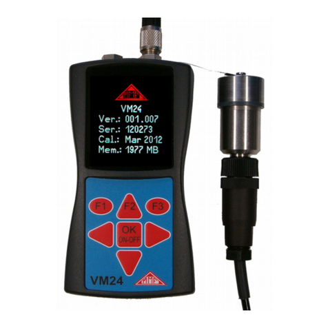
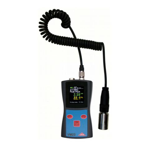
MMF VC120 User manual

Instruction Manual
Manfred Weber
Metra Mess- und Frequenztechnik in Radebeul e.K.
Meissner Str. 58 - D- 1445 Radebeul
Phone. +49-351 836 2191 Fax +49-351 836 294
Email: [email protected] Internet: www.MMF.de
Vibration
Calibrating
System
VC120

Published by:
Manfred Weber
Metra Mess- und Frequenztechnik in Radebeul e.K.
Meißner Str. 58
D-0 445 Radebeul
Phone 035 -836 2 9
Fax 035 -836 2940
Email Info@MMF.de
Internet www.MMF.de
Notice: The latest version of this document can be downloaded as PDF from
https://mmf.de/en/product_literature
Specifications subject to change without prior notice.
© 2023 Manfred Weber Metra Mess- und Frequenztechnik in Radebeul e.K.
Reprint only with permission.
Dec/ 23 # 94

Contents
.The Instrument at a Glance.....................................................................................3
2.Functions................................................................................................................4
3.Mounting of Test Object.........................................................................................5
4.Operation of the VC 20..........................................................................................7
4. .Switching the Unit On and Off........................................................................7
4.2.Basic Settings..................................................................................................7
4.3.Calibration..................................................................................................... 0
4.3. .Manual Calibration................................................................................
4.3.2.Calibration at Fixed Frequencies............................................................ 2
4.3.3.Frequency Response Measurement........................................................ 3
4.3.4.Calibration Errors and Their Reasons.................................................... 6
4.4.Saving Measuring Results............................................................................. 7
4.5.Retrieval of Stored Data................................................................................ 8
4.6.Other Settings................................................................................................ 9
4.6. .Autostart................................................................................................ 9
4.6.2.Distortion Calibration............................................................................ 9
4.6.3.Autoranging...........................................................................................20
5.PC software VC xxCDB......................................................................................2
5. .Installation.....................................................................................................2
5. . .Requirements.........................................................................................2
5. .2.Download and installation of the Software VC xxCDB........................2
5. .3.Installation of the USB-Driver for Windows 7 and 8.............................2
5. .4.First steps...............................................................................................24
5.2.Unlock Device...............................................................................................25
5.3.First steps......................................................................................................26
5.3. .The main window..................................................................................26
5.3.2.Starting the Help function......................................................................27
5.3.3.Manual Mode.........................................................................................28
5.4.Sensor Calibration.........................................................................................29
5.4. .Creating a Sensor Type..........................................................................29
5.4.2.Creating a Calibration Template............................................................30
5.4.3.Sensor Calibration Procedure.................................................................30
5.4.4.The Sensor View....................................................................................32
5.4.5.Creating a Calibration Report................................................................33
6.Interface Protocol.................................................................................................35
6. .Introduction...................................................................................................35
6.2.Instructions Without Data Return..................................................................36
6.2. .Parameter Instructions............................................................................36
6.2.2.Instructions for Data Acquisition...........................................................39
6.2.3.Instructions for Calibration....................................................................39
6.3.Instructions With Data Return.......................................................................39

6.4.First Connection with the PC........................................................................4
7.Power Supply.......................................................................................................42
8.Transport and Maintenance..................................................................................44
9.Technical Data......................................................................................................45
Appendix: Warranty
CE Declaration
2

1. The Instrument at a Glance
Front panel controls:
Rear panel connectors:
3
INPUT
USB
Mini-B
DC SUPPLY
14 .. 16 V
Metra Mess- und Frequenztechnik
in Radebeul e.K. GERMANY
SERIAL NO.
141 1
Serial
PC interface
Charge
socket
Sensor
socket
Grounding
socket
SIGNAL GROUND
POWE
F2
F1
SHAKE
ON/OFF
VC120 Vibration Calibrator
Menu
related
keys
Shuttle wheel
On/Off button
Battery LED
16 Hz
Shaker off
MENUmanualaccQ
coarse

Dear Customer,
We are glad about your decision to work with our Vibration Calibrating System
VC120. This instrument can be easily o erated by means of its self-ex laining dis-
lay. Nevertheless, you should s end some time to read this manual. This way you
will be ensured to use all functions of the instrument in the best ossible manner.
2. Functions
The Vibration Calibrating System VC 20 has been designed for calibration of vari-
ous kinds of vibration transducers. In spite of its compact case the instrument is
portable and features a variety of functions, which have been known only from far
more expensive systems up to this time. The most important features are:
·Vibration exciter for sine wave vibration from 70 Hz to 0 kHz
·Control of vibration level by an internal reference loop to the constant value of
m/s² (RMS)
·Calibration of specimen with a maximum weight of 400 g
·Calibration at fixed frequencies as well as measurement of frequency response
·Internal signal conditioning channel for transducer output, on screen display of
sensor sensitivity
·Menu controlled dialog for operation via LCD display and shuttle wheel
·PC software for automatic sensor calibration, report generation and data man-
agement
·ASCII command strings for controlling the VC 20 by customer software via
USB Serial Port (virtual COM-Port)
·Automatic switching the VC 20 on/off controlled by the PC software or Win-
dows energy management to reduce power dissipation
A piezoelectric actuator is used as vibration exciter allowing the compact size of
the instrument. This principle of excitation requires a sophisticated electronic cor-
rection to suppress harmonic distortion. For this purpose Metra developed a special
technique with the trademark ACHD (Active Compensation of Harmonic Distor-
tion).
4

3. Mounting of Test Object
The head of the shaker system is situated at the upper side of the case. The coupling
surface has a diameter of 20 mm. It possesses an M5 tapped hole in its center for
mounting the specimen.
The most reliable kind to attach the sensor under test is screwing.
Vibration transducers have a variety of different mounting threads. The VC 20
therefore includes some threaded adapters from M5, M8, /4”-28 and UNF 0-32 to
the M5 tapped hole of the shaker head. Other adapters are available on demand.
Screw attachment should be preferred at frequencies above kHz to prevent coup -
ling resonances. In addition, a thin layer of grease applied to the coupling surface is
recommended.
At lower frequencies a strong permanent clamping magnet may be used for mount-
ing. The shaker head therefore consists of magnetic steel.
Do not drop the magnet onto the shaker head to protect the VC 20 and the sensor
from shock acceleration. Gently slide the sensor with the magnet to the place.
Especially small transducers often have no mounting hole. In this case it is recommended
to use adhesive wax or cyanoacrylate glue.
Under no circumstances the specimen must wobble or come into contact with the shaker
head at only a few points. In such cases, as a result of the coupling resonances, the meas-
uring error may increase in a two-figure percentage.
When mounting the specimen pay attention to the symmetrical distribution of the object
weight. Otherwise the vibrating system may be deflected from its main axis. Especially,
when using coupling structures for calibration of transducers symmetrical attachment be-
comes very important (for instance at the calibration of the x and y axis of a triaxial ac-
celerometer). In this case it is recommended to use a balance weight (see the following
figure).
5
Figure : Balancing the weight of the object under test

For a perfect transmission of frequencies in the kilohertz range it is very important
to have a coupling surface without any scratches at the VC 20 shaker head as well
as at the sensor under test. The surface of the shaker head of VC 20 is flat grinded.
If it shows scratches after intensive use please send the instrument back to the man-
ufacturer for revision.
The accessories include a plastic washer which can be put between the shaker and
the test object. This will protect the shaker surface from scratches. It is not recom-
mended, however, to use the plastic washer above kHz.
Important: The maximum torque when attaching a sensor must not exceed 5 Nm,
otherwise the vibration exciter may get damaged.
The input for the sensor to be calibrated (BNC socket) is located at the rear of the
VC 20. Some transducers have cables with UNF 0-32 type or Microdot plugs. An
adapter for these cables is included in the accessories of the VC 20.
6

4. Operation of the VC120
This section exclusively describes o eration via the VC120 front anel. These o er-
ations and adjustments can also be done in an easier way by means of the included
PC software. For field use or cases where no PC is at hand, it may be useful to
study this cha ter.
4.1. Switching the Unit On and Off
Press the SHAKE ON/OFF key about s to switch on the VC 20. The instru-
ment now runs a self test and then displays the operation screen.
In the upper part of the window vibration frequency and below the measuring result
or the operating status are displayed. The menu bar at the lower part of the screen
shows the last before the instrument was switched off.
To switch off the instrument press the SHAKE ON/OFF button about 2 s, until
power off is indicated. After releasing the key the instrument switches off.
The current configuration of the instrument is automatically stored before it is
switched off. The VC 20 will start with the same configuration, when it is switched
on next time.
To start the VC 20 with the default manufacturer settings, press the SHAKE
ONOFF key and the F1 key simultaneously.
In case of a faulty operation press the key SHAKE ON/OFF about 5 s until Sys-
tem reset... is displayed. The VC 20 will start with the last settings.
If the battery voltage becomes too low, i.e. the accumulator is discharged, the
VC 20 will switch off automatically after saving the current configuration.
The VC 20 switches off immediately when the external power supply is interrupted
by disconnecting it from mains. It will start with the default configuration, when it
is switched on next time.
4.2. Basic Settings
Depending on the sensor type some settings of the signal conditioning channel must
be made. For this purpose, press the F2 key. The display shows a menu bar in its
bottom line:
7
Figure 2: Display
16 Hz
Shaker off
manual
Qacc
Input
type
Display
unit
Operation
mode
Shaker frequency
Operating status or
measuring result
Menu bar
Other menu
options
Button F1
meaning
MENU
coarse

Use the shuttle wheel to select a menu option. The selected option is inversely indic-
ated. Select the left option in the menu and press the F2 key again. Select the de-
sired input type by the shuttle wheel.
The following options are available:
IEPE: For sensors with integrated impedance converter to IEPE standard. The in-
put features a 4 mA constant current source.
U: The input is configured for AC voltage. Its impedance is higher than M.
This mode is suitable, for instance, for calibration of electrodynamic vibra-
tion transducers.
Q: The signal conditioning channel works as charge amplifier for piezoelectric
transducers.
Off: The measuring amplifier is switched off. This option is useful, if the VC 20
is used as vibration exciter only.
To confirm your choice press F1 (the display indicates OK). Leave the menu by
pressing F1 again (the display indicates ESC).
The VC 20 works in all operation modes with a constant acceleration of m/s²
(RMS). Nevertheless, the instrument can be used not only for calibration of acceler-
ometers, but also for calibration of velocity and displacement transducers. This is
realized by internal mathematical conversion of the physical quantities in depend-
ence of the frequency:
va
f
2
for velocity
and
da
f
22
for displacement.
Please note that the shaker magnitude limits the maximum calibration frequency at
calibration in velocity and even more at calibration in displacement quantities. At
8
Figure 4: Input type
Figure 3: Menu bar

high frequencies a very high amplification of the sensor signal would be required.
Therefore, the usable frequency range depends on transducer sensitivity. The min-
imum input signal of the sensor is 0. 2 mV for voltage input and 0. 2 pC for charge
input.
Select the required physical quantity in the menu bar, which is accessed by pressing
the F2 key. Use the shuttle wheel to select the second position from the left and
press F2 again:
The following options are available:
acc: Vibration acceleration
vel: Vibration velocity
disp: Vibration displacement
bias: Bias voltage of IEPE compatible sensors.
Select the required physical quantity by the shuttle wheel and confirm by pressing
F1. Leave the menu by pressing F1 again.
IEPE bias voltage is measured only when IEPE input was selected. The vibration
exciter is switched off during this operation.
Occasionally accelerometers are not calibrated in the SI standard unit m/s², but in
units of g (gravitational constant, g = 9.807 m/s²). The VC 20 may display acceler-
ation in g, although it still calibrates at m/s². Switch to g display in the right field
of the menu bar (MENU). To enter the MENU option press F2 key. The screen dis-
plays the sub-menu OPTIONS. Use the shuttle wheel to select Signal Cond. and
confirm by pressing F2 (the display indicates SEL):
Now the sub-menu Signal Conditioner will appear:
9
Figure 6: Signal conditioning options
Figure 5: Vibration quantity

Select Units by the shuttle wheel and confirm by F2 (the display indicates SEL).
Choose by the shuttle wheel between:
metric (indication in units of m/s²) or
imperial (indication in units of g).
Confirm the selection by pressing F2 again (the screen displays OK) and leave the
menu by pressing F1 three times (the screen displays ESC).
After finishing all basic settings of the VC 20 you can start now with calibration.
4.3. Calibration
After the specimen has been mounted and connected and all basic settings have
been completed, you can start with calibration.
The VC 20 provides 3 modes of calibration which differ by their frequency control.
·Manual: The calibration frequency is adjusted by the shuttle wheel. Coarse ore
fine tuning are available.
·Table of fixed frequencies: You can select from a table of up to 0 frequen-
cies. Switch from one to the other frequency by the shuttle wheel.
·Frequency response: The VC 20 automatically sweeps through the fre-
quency range. The minimum and maximum frequency as well as the increment
can be selected in advance.
The vibration exciter is activated only during measuring operation. It is ready
within 2 s after switching on the instrument. We recommend to keep measure-
ments as short as possible to reduce power consumption and to extend battery
operating life.
0
Figure 7: Selecting metric or imperial units

4.3.1. Manual Calibration
The simplest way to calibrate a sensor is calibration at a fixed frequency adjusted by
the shuttle wheel. At first switch the VC 20 into the manual calibration mode.
Then press F2 to enter the menu and select the third field from the left using the
shuttle wheel. Activate it by pressing F2 again. Now select manual by the shuttle
wheel and confirm by F1 (indication on the display: OK)
Leave the menu by pressing F1 again (indication on the display: ESC).
Now you can adjust the frequency by the shuttle wheel. The frequency is indicated
in the upper line of the display. The VC 20 offers two modes of tuning:
fine and coarse. Switch from one to the other mode by pressing F1.
In the coarse tuning mode the frequency is changed in steps of:
·5 Hz from 70 Hz up to 00 Hz
·20 Hz from 00 Hz up to 000 Hz
·00 Hz at frequencies higher than 000 Hz.
In the fine tuning mode the frequency is tuned in steps of Hz for frequencies be-
low 000 Hz. At higher frequencies the steps become wider due to the digital fre-
quency synthesis of the VC 20.
The vibration exciter is switched on by pressing the SHAKE ON/OFF button,
and measurement is started. The line in the center of the display indicates the sensit -
ivity of the tested sensor with the selected unit.
The calibration frequency can be changed during measurement by the shuttle wheel.
The instrument automatically searches for the optimal gain range (display: autor-
ange xx dB), provided that the autoranging function is activated (see chapter 4.6).
The measurement will be terminated by pressing the SHAKE ON/OFF key again.
By pressing F1 the measuring value will be saved (display: SAVE, see chapter 4.4).
Figure 9: Tuning mode
Figure 8: Manual calibration

4.3.2. Calibration at Fixed Frequencies
Sometimes it is advisable to calibrate a sensor at more than one frequency. For this
purpose a table of up to 0 frequencies can be stored in the VC 20. Switch from
one to the other frequency using the shuttle wheel.
Fixed frequencies are set in the menu bar (activated by F2, select MENU by shuttle
wheel, press F2 again). Now select Fix Frequencies by the shuttle wheel.
Activate Fix Frequencies by pressing F2 again and enter the setup menu.
Fixed frequencies are marked F to F9. To set a fixed frequency (for instance F1)
select it by the shuttle wheel and press the SEL key (F2). Now adjust the frequency
by the shuttle wheel. After pre-selecting in the coarse mode activate the fine-tuning
mode by pressing F2 (display: fine). After selecting the required frequency press
F2 again (indication on the display: OK). Now you can adjust the other fixed fre-
quencies in the same way. Leave the menu by pressing F1 three times (display:
ESC).
Each change of an entry in the menu can be aborted by pressing F1 (ESC). The ori-
ginal value will be restored.
To delete a fixed frequency select it by the shuttle wheel (for instance F3) and press
the SEL key (F2). Now turn the shuttle wheel to the left (anti clockwise) until 70
Hz is reached. The display now indicates instead of a frequency: none. Leave this
mode by pressing F2 twice and the selected fixed frequency is deleted.
2
Figure : Entering fixed frequencies
Figure 0: Selecting fixed frequencies
Figure 2: Deleting a fixed frequency

The fixed frequency F0 cannot be deleted.
To calibrate with the selected fixed frequencies enter the menu by the F2 key. Se-
lect in the third field from the left (by shuttle wheel and F2) the function fix and
confirm by F1. Leave the menu by pressing F1.
Pressing the SHAKE ON/OFF key starts the measurement. Change between the
fixed frequencies by the shuttle wheel.
Fixed frequencies are only indicated, if they have been set before (F...). Fixed fre-
quencies remain stored even if the instrument is switched off.
Pressing the SHAKE ON/OFF key again finishes the measurement. By pressing
F1 the measuring value will be stored (indication on the display: SAVE, see chapter
4.4).
4.3.3. Frequency esponse Measurement
Measuring frequency sweep diagrams allows a better function check of vibration
transducers. Frequency sweeps allow to detect sensor defects which may cause
sharp resonance peaks particularly at higher frequencies. Such resonances would
possibly not be noticed at calibration with fixed frequencies. The VC 20 allows fre-
quency response measurements between 70 Hz and 0 000 Hz. This covers the lin-
ear frequency range of most vibration transducers. Measured data will be down-
loaded from the VC 20 via the serial interface to a PC and visualized by the in-
cluded software (see chapter Fehler: Verweis nicht gefunden). Frequency sweep dia-
grams cannot be displayed by the VC 20 itself.
Frequency response parameters are set in the menu as follows: Activate the menu by
F2, select MENU by the shuttle wheel, press F2 again, select Frequency esp.
by the shuttle wheel.
After pressing F2 again the display shows the set up menu for frequency response.
3
Figure 3: Calibration at fixed frequencies
Figure 4: Selecting frequency response menu

Select the position to be edited by the shuttle wheel and press SEL (F2). Select the
value or option using the shuttle wheel. Press F2 when the required value or option
is indicated (display: OK).
Now other frequency response settings can be made.
The following options are selectable:
fmin: Start frequency for frequency response measurement,
fmax: Stop frequency for frequency response measurement,
Increase: Mode of frequency increase. The following options are available:
geom.: Frequency points with geometric progression, i.e. two successive fre-
quencies are connected by the same constant factor. A constant distri-
bution with equal intervals will be obtained in a logarithmic frequency
scale.
linear: Frequency points with arithmetic progression, i.e. the difference
between two successive frequencies has always the same amount.
Hz/Points: Indicates the density of frequency points. Possible values are 0, 25, 50
and 00. In case of geometric progression this value corresponds to the
number of frequency points of a frequency decade. With arithmetic
progression this value is the increase in Hz.
fflip: Switch frequency to a higher density of frequency points.
With geometric progression from this point on the density of fre-
quency points increases to 00 frequency points per decade.
With arithmetic progression, from this point on the frequency step,
selected under Hz/Points, is reduced to one tenth.
Increasing the density of frequency points may be useful, for instance,
if the expected changes in the frequency response are in a particular
frequency range. This will often be near the resonant frequency, as
shown in the following illustration:
4
Figure 5: Frequency response settings

Exit the menu by pressing F1 three times (display: ESC).
After all adjustments have been completed, you can start frequency response meas-
urement. To activate the frequency response mode select in the menu (F2) the third
field from the left (shuttle wheel and F2), choose the function sweep and confirm
with F1.
Leave the menu by pressing F1 again. The display now indicates the start frequency
fmin and the measurement is started by pressing F1 (Start).
Pressing F1 (Stop) again interrupts the measurement.
A PC is necessary to display the frequency response curve. Further operation in the
frequency response mode is done by the supplied software (see chapter Fehler: Ver-
weis nicht gefunden).
5
Figure 8: Starting sweep measurement
Figure 7: Selecting sweep mode
Figure 6: Increasing the density of frequencies
f
A
fflip
low density high density

4.3.4. Calibration Errors and Their easons
Stable condition of the sensor signal is checked permanently by the reference and measur-
ing circuit of the VC 20. Over a time interval of 200 ms 30 values are measured and aver-
aged. If the standard deviation becomes higher than 0.5 % the instrument will show no res-
ult. If this condition persists longer than 4 s the display will indicates unstable signal. If
the standard deviation drops below 0.5 % a measuring value is indicated again. In case of
an unstable signal during frequency response measurement the concerned frequency points
will be skipped and not be indicated.
If the indication Unstable signal frequently appears, a reliable calibration cannot
be achieved. Reasons can be:
·A noisy sensor signal,
·Interference between mains and sensor signal,
·Low frequency vibrations for example impact sound by footsteps
For measurements under inadequate conditions the accuracy criterion of the VC 20
can be reduced. Select MENU (confirm by F2) in the sub-menu Signal Cond.
(confirm by F2). Now use the shuttle wheel to select Accuracy, press F2 and se-
lect again by the shuttle wheel high or low. The difference between these two op-
tions is:
·high: The standard deviation must not exceed 0.5 %.
·low: The standard deviation may reach up to 0 %.
Calibration in the low position has only informative character. This position should be
used only in particular cases, if a more accurate result in the high position cannot be
reached.
If the sensor signal is out of the measuring range for any reason, the VC 20 indic -
ates this as follows:
too low: The sensor signal is lower than 0. 2 mV or 0. 2 pC. Possible reasons are
a defective sensor or a short-circuited cable.
overload: The sensor signal is higher than .2 V or 200 pC. A possible reason is inter-
ference from mains due to a broken cable.
When the instrument continuously indicates too low or overload, check in the MENU
under Signal Cond. if the option Gain is set to auto.
If the VC 20 frequently indicates errors or does not reach a stable operating condition, it
may be restarted with default settings (see chapter 4. ).
6

4.4. Saving Measuring esults
The VC 20 features an internal memory for calibration results. Stored data can be
downloaded later to a computer for archiving. The VC 20 can store up to 00 re-
cords. The following parameters are stored in a record:
·Measuring value (sensitivity, bias voltage)
·Unit
·Frequency
·Name with consecutive record number
Measurement of sensitivity or IEPE bias voltage is finished by pressing the
SHAKE ON/OFF key.
The display indicates the last measured value with the belonging frequency and next
to the F1 button the indication SAVE:
Enter the saving mode by pressing F1:
Now you have two options:OK: Add a new record to an existing name (in
the example the name is DEFAULT). The three-figure number after the name is the
record number. The next free record number appears automatically. The measur-
ing value will be stored by pressing the F key. To overwrite an existing record
number, select the desired number by the shuttle wheel:
Confirm by F1 or press F2 to abort.
7
Figure 20: Saving a result
Figure 9: Entering the save menu
Figure 2 : Overwriting an existing value

NEW: A new record name can be created as well. For this purpose, press F2. In the
next menu screen you are asked for the name:
Fill in the name by the shuttle wheel. Turning it to the left (anti-clockwise)
the numerals will appear, turning it to the right the letters will appear. Enter
the next text position by pressing F2. The name may consist of letters or nu-
merals in any order. Its maximum length is 8 digits. Confirm the entered
name by F1. Press F1 again to save the first record with the automatically
added number 000 or abort by F2.
4.5. etrieval of Stored Data
As described in the previous chapter all measured calibrating results can be stored in
the internal memory of the VC 20. For retrieval of the stored data the instrument
has a view function. To enter this mode activate the menu by the F2 key. Mark the
third field from the left side by the shuttle wheel and confirm this by pressing F2
again. Select the view mode by the shuttle wheel and confirm this by pressing F1
twice.
Now you can search by the shuttle wheel for the stored records. They appear in the
order they have been stored (not in the order of their numbers). The upper line on
the display shows the name and number of the record. Below the stored measuring
value is displayed.
Records are deleted by pressing the F1 key (display indication: DEL). Press F2
(OK) to confirm. Pressing F1 (ESC) will abort the operation.
Return to the menu by F2 and select in the third field from the left another mode
(once more F2).
4.6. Other Settings
4.6.1. Autostart
In the sub-menu Shaker System you will find some settings, which are not often
required. To enter this sub-menu press F2 for the menu bar, select MENU by the
8
Figure 23: Viewing stored results
Figure 22: Entering a name
Table of contents
Other MMF Measuring Instrument manuals
Popular Measuring Instrument manuals by other brands

SKF
SKF THGD 100 Instructions for use

Büttner Elektronik
Büttner Elektronik Dometic MT iQ Basic Pro Installation and operating manual

Siemens
Siemens SITRANS F M MAG 5000 operating instructions

Sper scientific
Sper scientific 840065 instruction manual

NeurOptics
NeurOptics NPi-300 Instructions for use

Fortinet
Fortinet FortiAnalyzer-100A Administration guide