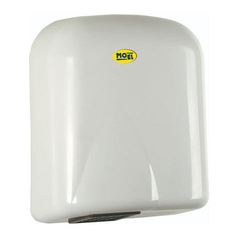
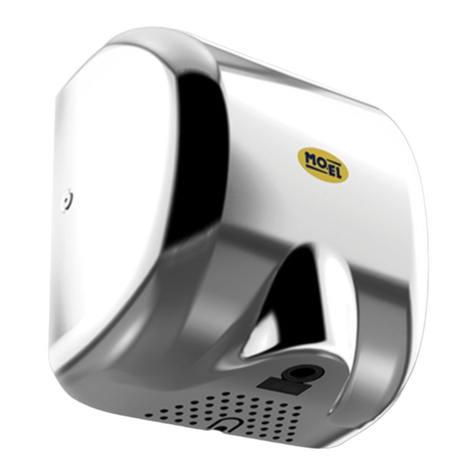
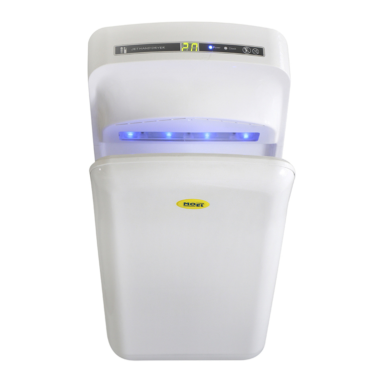
MO-EL 315 User guide

USE AND MAINTENANCE
EMPLOI ET ENTRETIEN
GEBRAUCH UND WARTUNG
ELECTRONIC HANDS-DRYER
505332F
505315F
CUISIMAT

EN USE AND MAINTENANCE
IMPORTANT SAFETY INSTRUCTIONS
Before using your appliance, read carefully the instructions contained
in this booklet, which furnish important information regarding instal-
lation, use and maintenance safety. The booklet must be keeped and
delivered to the new user in case of cession of the machine.
1. This appliance is intended exclusively for the use for which it was
created, to dry the hands by means of flowing warm air, and the
Producer would not be considered responsible for any damage
caused by its improper use.
2. After opening the packing, make sure the appliance is sound and
has no visible damage or signs of tampering. If in doubt, do not
use the appliance and call your supplier or fitter.
3. Keep the packing materials (plastic bags, polystyrene, nails, etc.)
well out of the reach of children as they are a potential hazard.
4. Installation must be carried out by skilled and qualified technical
personnel, following the instructions provided by the manufac-
turer. Failure to observe the installation recommendations may
jeopardize safety.
5. The appliance is not suited for persons (as well as children) physi-
cally, mentally, sensory disabled, or with no experience, unless
they have been supervised or directed by someone responsible
of their safety.
6. Do not let children or incompetent people use device without su-
pervision.
7. Before carrying out any cleaning disconnect the mains electrical
supply by means of the double pole switch.
sThe electronic handdryer Art. 315 / 316 / 332 has been designed
for permanent installation on the mains.
sThe unit must only be attached to the wall with the air out-
let facing downward.
sA bipolar circuit breaker with contact opening distance of at
least 3 mm must be fitted upstream from the supply line.
FR EMPLOI ET ENTRETIEN
INSTRUCTIONS IMPORTANTES POUR LA SÉCURITÉ
Avant d’utiliser votre appareil suivez les recommandations contenues
dans cette notice car elles donnent des informations importantes en
ce qui concerne l’installation, l’utilisation et la sécurité de mainte-
nance. Le manuel doit être conservé et transmis au nouvel usager en
cas de cession de l’appareil.
1. Cet appareil est uniquement destiné à l’utilisation pour laquelle il a
été conçu, c’est à dire sécher les mains pour moyen d’un flux d’air
chaud. Le Fabricant ne pourra être tenu pour responsable en cas
de dommage occasionné par un usage non-approprié.
2. Après avoir déballé le produit vérifiez la perfection du contenu en
consultant le tableau de la dernière page et assurez-vous que le
produit ne présente pas de signes de ruptures, d’endommage-
ments ou d’effractions.
3. Garder le matériel d’emballage loin des enfants, car il peut être
source de danger.
4. L’installation doit être effectuée par un personnel technique
compétent et qualifié, en suivant les instructions fournies par le
constructeur. Ne pas respecter les consignes d’installation peut
compromettre la sécurité.
5. L’appareil n’est pas approprié pour des personnes (aussi bien que
des enfants) physiquement ou mentalement handicapées, ou avec
handicaps sensoriels, ou sans expérience, à moins qu’ils aient été
instruites ou dirigés par quelqu’un responsable de leur sûreté.
6. Ne pas laisser utiliser par des enfants ou des incapables sans sur-
veillance.
7. Éteignez l’appareil avant de le nettoyer.
sLe sèche-mains à commande électronique Art. 315 / 316 /
332 est un appareil étudié pour une installation fixe sur sec-
teur.
sL’appareil doit être fixé exclusivement au mur et le jet d’air
dirigé vers le bas.
sVous devrez monter en amont un interrupteur bipolaire
ayant une ouverture des contacts d’au moins 3 mm.
ART. 315 / 332
MOUNTING INSTRUCTIONS
1. Apply the drilling template on the wall using adhesive tape and
punch in the points marked.
2. Drill holes in the wall using a 9 mm bit in the 5 points indicated.
3. Loosen the three Allen screws that attach the body to the base,
then remove the body.
4. Hookup:
sArt. 315: as this is a Class II device, the earth connection does
not have to be made. Connect Phase and Neutral on the two
free terminals that are indicated by the arrows.
sArt. 332: as this is a Class I device, the earth connection has to
be made. Connect Phase and Neutral on the two free terminals
that are indicated by the arrows; connect the earth on the ter-
minal that is indicated by the symbol
5. Connect the 5 screw anchors to the base using the screws pro-
vided, leaving some slack; place the 5 screw anchors in the holes
made previously (point 2), then press the base against the wall;
tighten the screw thoroughly.
6. Refit the body, making sure that the photoelectric cell wires do
not touch each other.
APPLIANCE SETTING
Detection sensitivity adjustment is made using the potentiometer
shown in the following diagram, with higher sensitivity
to the left and lower to the right. If sensitivity is too high, the device
will function continuously in illuminated rooms.
In all cases, the dryer must be attached in such a way that the sen-
sors are at least 50 cm from horizontal surfaces in order to prevent
infrared reflection.
PRECAUTIONS
During transport, one of the three sensors may come out of its seat
slightly. For the best dryer operation, the sensors must be well-seated
(especially the middle one). If necessary, carry out this operation care-
fully, making sure that the tangs of the LEDs do not come into contact
with each other. N.B. The blue sensors are infrared transmitters and
the white sensor is a receiver.
ART. 316
INSTALLATION INSTRUCTIONS
Before installing the appliance make sure the power supply voltage is
the same as indicated on the rating plate on the appliance.
1. Unscrew the three Allen screws fixing the bodywork on the fan
casing, then take off the bodywork.
2. Unscrew the other three Allen screws fixing the fan casing onto
the base.
3. Apply the base on the wall in the desidered position and mark
three points for drilling the holes.
4. Drill the wall at the three points marked using a 9mm bit.
5. Join the three expansion plugs to the base by means of the
screws, leaving a certain amount of play; insert the plugs into the
holes previously made and then press the base against the wall.
Tighten the screws fully to complete fixing.
6. Connection: overall construction of the appliance is to Class II
(double insulated) and does not require earthing. Thread the in-
coming cable through the channel and connect the live and neu-
tral wires to the terminal block as indicated by the arrows.
7. Fit the fan casing and the bodywork back on, taking special care
over positioning thephotoelectric cells correctly.
ADJUSTING THE APPLIANCE
The appliance normally needs no adjustment as this is done during
manufacture, nonetheless in some cases it may be necessary. The
recognition sensitivity is adjusted by means of the trimmer on the
electronic card: greater sensitivity to the right and less sensitivity to
the left. Too high a sensitivity of the appliance involves constant and
permanent operation in an illuminated environment.
In any case, the appliance must be positioned so that the sensors are
at least 1 metre from the floor or any other horizontal surfaces (espe-
cially if reflecting) so as to prevent undesired activation.
INSTRUCTIONS FOR USE
Move your head close to the appliance, it will automatically activate.
On moving away the appliance will automatically shut down after a
few seconds.
CUISIMAT

ART. 315 / 332
INSTRUCTION DE MONTAGE
1. Appliquez au mur le gabarit de perçage avec du ruban adhésif et
marquez l’emplacement des trous.
2. Percez le mur avec une mèche de 9 mm aux 5 points indiqués.
3. Dévissez les trois vis 6 pans de fixage de la structure sur le em-
base, puis retirez cette dernière.
4. Branchement:
sArt. 315: l’appareil étant de Classe II, vous ne devez pas ef-
fectuer la mise à la terre. Raccordez phase et neutre aux deux
bornes libres indiquées par les flèches.
sArt. 332: l’appareil étant de Classe I, vous devez effectuer la
mise à la terre. Raccordez phase et neutre aux deux bornes
libres indiquées par les flèches et la mise à la terre dans le borne
libre indiqué de
5. Montez les 5 vis tamponnées sur la base, en laissant un peu de
jeu. Enfilez les trois tasseaux dans les trous percés au préalable
(point 2), appuyez la base contre le mur et serrez les vis à fond.
6. Remontez la carrosserie en veillant bien à ce que les fils des pho-
to-cellules ne se touchent pas.
REGLAGE DE L’APPAREIL
Réglez la sensibilité de détection à l’aide du potentiomètre figurant sur
le schéma ci-dessous: plus sensible à gauche, moins sensible à droite.
Si l’appareil est trop sensible, il fonctionnera en permanence dans un
milieu éclairé. En tout cas, l’appareil doit être fixé de manière que les
capteurs soient à au moins 50 cm de toute surface horizontale pour
éviter la réflexion des infrarouges.
PRECAUTIONS
L’un des trois capteurs pourrait pendant le transport sortir légèrement
de son logement. Pour que l’appareil fonctionne bien, les capteurs
doivent être bien enfoncés (surtout celui du milieu). Exécutez cette
opération avec prudence et faites en sorte que les tiges des compo-
sants ne se touchent pas.
N.B. Les capteurs bleus sont des émetteurs d’infrarouges et le blanc
un récepteur.
ART. 316
INSTRUCTIONS POUR L’INSTALLATION
1. Dévissez les trois vis 6 pans de fixage de la structure sur le corps
ventilateur, puis retirez cette dernière.
2. Dévissez les trois autres vis 6 pans de fixage du corps ventilateur
qui se trouve sur l’embase.
3. Appliquez l’embase sur le mur, dans la position voulue et marquez
trois points à l’endroit desquels vous ferez les trous.
4. Percez le mur aux trois points indiqués, en utilisant une pointe de
9mm.
5. Unissez à l’embase les trois vis tamponnés, à l’aide des vis spé-
ciales, en laissant un certain jeu; enfilez les tasseaux dans les
trous percés au préalable puis appuyez l’embase contre le mur.
Vissez les vis à fond pour fixer le tout correctement.
6. Branchement: étant donné qu’il s’agit d’un appareil de classe II,
il ne faut pas effectuer de branchement à terre. Faites passer le
câble dans le tunnel spécial et reliez la Phase et le Neutre dans les
deux bornes libres indiquées par les flèches.
7. Remontez le corps ventilateur et la structure, en faisant particulière-
ment attention au positionnement correct des cellules photo-élec-
triques.
REGULATION DE L’APPAREIL
Normalement, l’appareil ne devrait pas avoir besoin de régulation
puisque cette dernière est effectuée pendant la construction; toute-
fois, dans certain cas, elle peut s’avérer nécessaire. La régulation de la
sensibilité de perception a lieu par l’intermédiaire du trimmer placé sur
la carte électronique: plus de sensibilité à gauche. Une sensibilité trop
élevée provoque un fonctionnement constant et permanent de l’appa-
reil dans un lieu éclairé. De toute façon, l’appareil doit être positionné
de manière que les détecteurs se trouvent au moins à 1 mètre de dis-
tance du sol ou d’un plan horizontal (surtout si ces derniers reflètent),
afin d’éviter des activations non voulues.
MODE D’EMPLOI
Approchez la tête de l’appareil: ce dernier s’allumera automatique-
ment. Eloignez-vous à l’appareil, il s’éteindra automatiquement
quelques secondes après.
DE GEBRAUCH UND WARTUNG
WICHTIGE HINWEISE ZU IHRER SICHERHEIT
Die nachfolgenden Hinweise aufmerksam lesen, da sie wichtige An-
gaben über die Sicherheit im Hinblick auf Installation, Gebrauch und
Wartung des Gerätes enthalten. Dieses handbuch ist aufzubewahren
und bei abgabe des geräts an den neuen anwender zu übergeben.
1. Dieses Gerät darf ausschließlich für den vorgesehenen Zweck ver-
wendet werden, das heißt zu trocknen die Hände für Mittel von
ein Fluß von warme Luft. Der Hersteller übernimmt keine Haftung,
für Schäden am Gerät, die durch unsachgemäße Handhabung ent-
standen sind.
2. Bitte prüfen Sie das Gerät nach dem Auspacken auf Vollständigkeit
und auf sichtbare Beschädigungen.
3. Stellen Sie sicher, daß die Verpackungsmaterialien (Plastikhüllen,
Polystyrolschaum, usw.) für Kinder unzugänglich aufbewahrt wer-
den und keine Gefahrenquelle darstellen.
4. Die Installation muß von technischem, qualifiziertem Fachpersonal
gemäß der vom Hersteller gelieferten Anweisungen ausgeführt
werden. Durch Nichteinhalten der Einbauempfehlungen kann die
Sicherheit des Gerätes beeinträchtigt werden. Vor der Installation
des Gerätes muß überprüft werden, ob die Spannung der Zulei-
tung den Daten auf demTypenschild entspricht.
5. Vor jeglicher Wartung ist es nötig das Gerät vom elektrischen
Stromnetz abzuschalten.
6. Das Gerät ist zu Personen (genauso wie Kinder) nicht passend, die
physisch oder geistig behindert oder mit sensorischen Schwach-
punkten sind, es sei denn, daß sie durch fuer ihre Sicherheit ver-
antwortliche Person unterrichtet oder geleitet worden sind
7. Achten Sie darauf, daß keine unbefugten Personen oder Kinder
das Gerät ohne Aufsicht nutzen.
sFest installierter elektrischer handtrockner Art. 315 / 316 /
332 Montage nur an der Wand mit nach unten gerichteter
Öffnung.
sVor dem Anschluß des Spannungsnetzes muß ein allpoliger
Schalter mit einem Kontaktöffnungsabstand von mind. 3
mm eingebaut werden.
ART. 315/332
MONTAGEANLEITUNG
1. Die Bohrschablone mit Klebeband an der vorgesehenen Montage-
stelle befestigen und die vorgezeichneten Bohrlöcher ankörnen.
2. Die 5 Bohrlöcher mit einem 9 mm Bohrstift ausführen.
3. Die drei Inbusschrauben, die zur Befestigung dienen, aus der Ab-
deckung herausschrauben, und die Abdeckung abnehmen.
4. Anschluß:
sArt. 315 : Da es sich um ein Gerät der Klasse II handelt, ist eine Er-
dung nicht notwendig. Phase und Nulleiter auf den beiden freien,
durch die Pfeile bezeichneten Klemmen verbinden.
sArt. 332 : Dieses Gerät hat die Schutzklasse I, welches unbe-
dingt geerdet werden muss. Schliessen Sie die Anschlussleitun-
gen der Phase und des Nulleiters an die dafür vorgesehenen,
mit Pfeilen gekennzeichneten Klemmen an. Die Erdungsleitung
wird an die durch das Erdungssymbol gekennzeichnete Klemme
angeschlossen
5. Die 5 Spreizdübel locker in den Unterbau schrauben; den Unterbau
gegen die Wand drücken und die Dübel in die vorbereiteten Bohr-
löcher schrauben (vgl. Pkt. 2) und fest eindrehen.
6. Die Abdeckung montieren, wobei darauf zu achten ist, daß die Kabel
der Photozellen nicht untereinander in Berührung kommen.
GERAETSEINSTELLUNG
Die Sensibilität kann durch das in obigem Schema gekennzeichnete
Potentiometer eingestellt werden: empfindlicher in linke Richtung und
weniger empfindlich in rechte Richtung. Eine zu große Sensibilität des
Gerätes führt bei heller Beleuchtung zu Dauerbetrieb. Das Gerät muß
so installiert werden, daß die Sensoren mindestens 50 cm Abstand zu
horizontalen Flächen haben, um Infrarotrückstrahlung zu vermieden.
CUISIMAT

SICHERHEITSHINWEISE
Während des Transportes kann eventuell einer der drei Sensoren aus
seinem Sitz herausrutschen. Für einen einwandfreien Betrieb müssen
die Sensoren immer tief in ihren Sitzen montiert sein (besonders der
mittlere Sensor). Falls erforderlich, sollte dieser Eingriff mit äußerster
Sorgfalt ausgeführt werden, um Kontakte zwischen den Ledträgern
zu vermeiden. Hinweis: Die blauen Sensoren sind Infrarotsender, der
Weiße ist ein Empfänger.
ART. 316
INSTALLATIONSANWEISUNG
1. Die drei Innensechskant-Befestigungsschrauben des Chassis am
Ventilatorkörper lösen und dann das Chassis abnehmen.
2. Die letzten drei Befestigungsschrauben des Ventilatorkörpers an
der Abdeckung lösen.
3. Die Abdeckung in der gewünschten Position an die Mauer anlegen
und die drei Punkte anzeichnen, wo die Bohrungen vorgenommen
werden sollen.
4. Die Bohrungen mit einem 9mm Bohrer durchfuhren.
5. Die drei Spreizdübel mit den entsprechenden Schrauben leicht an der
Abdeckung anschrauben; die Dübel in die vorbereiteten Bohrungen in
dieWand einführen und dann die Abdeckung an dieWand pressen. Die
Schrauben für eine perfekte Befestigung fest anschrauben.
6. Stromanschluß: Da es sich hier um ein Gerät der Klasse II handelt,
ist eine Erdung nicht nötig. Leiten Sie das Kabel durch den dafür
vorgesehenen Kanal und schließen Sie Phase und Neutral an die
zwei freien Klemmen (siehe Pfeile) an.
7. Montieren Sie den Ventilatorkörper und das Chassis wieder zusam-
men: achten Sie besonders auf die richtige Lage der Fotozellen.
GERÄTEEINSTELLUNG
Das Gerät bedarf normalerweise keiner Einstellung, das es bereits bei
der Herstellung reguliert wird; trotzdem kann sie sich in einigen Fällen
als notwendig erweisen. Die Einstellung der Wahrnehmungsempfind-
lichkeit erfolgt mit Hilfe des auf der elektronischen Platine sitzenden
Trimmers; rechts: höhere Empfindlichkeit - links: geringere Empfind-
lichkeit. Eine zu ausgeprägte Empfindlichkeit des Geräts kann in einer
sehr hellen Umgebung einen ununterbrochenen Betrieb auslösen. Auf
alle Fälle muß das Gerät so angebracht sein, daß die Sensoren min-
destens 1 Meter Abstand vom Boden oder von anderen horizontalen
Oberflächen haben (besonders, wenn diese reflektieren), um uner-
wünschte Inbetriebsetzungen zu vermeiden.
BEDIENUNGSANLEITUNG
Nähern Sie sich mit dem Kopf dem Gerät: das Gerät schaltet sich au-
tomatisch ein. Wenn Sie sich vom Gerät entfernen, schaltet sich das
Gerät automatisch nach wenigen Sekunden aus.
CUISIMAT

Important information concerning
the environmentally compatible
disposal of the appliance
Information importante pour
l’élimination compatible avec
l’environnement
Wichtige Information für den
Benutzer zur umweltfreundlichen
Entsorgung des Gerätes
Belangrijke informatie
over milieuvriendelijke
afvalverwerking
EN IMPORTANT
This product conforms to EU
Directive 2002/96/EC.
This appliance bears the symbol of
the barred waste bin. This indicates
that, at the end of its useful life,
it must not be disposed of as
domestic waste, but must be taken
to a collection centre for waste
electrical and electronic equipment,
or returned to a retailer on purchase
of a replacement.
It is the user’s responsibility to
dispose of this appliance through
the appropriate channels at the end
of its useful life. Failure to do so
may incur the penalties established
by laws governing waste disposal.
Proper differential collection,
and the subsequent recycling,
processing and environmentally
compatible disposal of waste
equipment avoids unnecessary
damage to the environment and
possible related health risks, and
also promotes recycling of the
materials used in the appliance.
For further information on waste
collection and disposal, contact your
local waste disposal service, or the
shop from which you purchased the
appliance.
their responsibilities for recycling,
processing and environmentally
compatible disposal either directly
or by participating in collective
systems.
FR ATTENTION
Ce produit est conforme à la
directive EU 2002/96/EC.
Le symbole représentant une
poubelle barrée présent sur
son cycle de vie, il devra être
traité séparément des déchets
domestiques. Il devra donc être
sélective pour appareils électriques
et électroniques ou rapporté au
revendeur lors de l’achat d’un
nouvel appareil.
L’utilisateur est responsable de
la remise de l’appareil usagé aux
structures de collecte compétentes
sous peine des sanctions prévues
par la législation sur l’élimination
des déchets.
La collecte sélective réalisée
avant le recyclage, le traitement
et l’élimination compatible avec
l’environnement de l’appareil usagé
contribue à éviter les nuisances
pour l’environnement et pour la
santé et favorise le recyclage des
matériaux qui composent le produit.
Pour de plus amples informations
concernant les systèmes de collecte
existants, adressez-vous au service
local d’élimination des déchets
ou au magasin qui vous a vendu
l’appareil.
Les fabricants et les importateurs
optempèrent à leur responsabilité
en matière de recyclage, de
traitement et d’élimination
des déchets compatible avec
l’environnement directement ou
par l’intermédiaire d’un système
collectif.
DE ACHTUNG
Dieses Gerät entspricht der EG-
Richtlinie 2002/96/EG.
Das Symbol mit der
durchgestrichenenAbfalltonne am
Gerät bedeutet, dass das Gerät
nach seinerAussonderung nicht im
Haushaltsmüll entsorgt werden darf,
sondern an einer Sammelstelle für
Elektro- und Elektronikgeräte oder
beim Kauf eines gleichwertigen
Neugerätes beim Händler
abzugeben ist.
Der Benutzer hat Sorge zu tragen,
dass das Gerät nach seiner
Aussonderung an einer geeigneten
Sammelstelle abgegeben wird. Ein
Nichtbeachten dieser Vorschrift ist
gemäß der geltendenAbfallordnung
strafbar.
Das geeignete Sortieren von
Abfall und nachfolgende Recyceln
des aussortierten Gerätes zur
umweltverträglichen Entsorgung
trägt zum Schutz von Umwelt
und Gesundheit bei und dient
der Wiederverwendung der
recyclingfähigen Materialien, aus
denen das Gerät besteht.
Für detailliertere Informationen
bezüglich der verfügbaren
Sammelsysteme wenden Sie sich
an lhre örtliche Behörde oder an
den Händler, bei dem Sie das Gerät
gekauft haben.
Die Hersteller und Importeure
umweltfreundlichen Recycling,
Verarbeiten und Entsorgen sowohl
direkt als auch durch Teilnahme an
einem Kollektivsystem nach.
NL LET OP
Dit apparaat is conform de EU
Richtlijn 2002/96/EC.
Het symbool op het apparaat met
de afvalbak met een kruis erdoor
geeft aan dat het apparaat, aan
het einde van de levensduur, niet
bij het huisvuil gezet mag worden
maar ingeleverd moet worden
bij een centrum voor gescheiden
afvalinzameling voor elektrische
en elektronische apparaten of
teruggegeven moet worden aan
de winkel op het moment van de
aanschaf van een gelijkwaardig
nieuw apparaat.
De gebruiker is verantwoordelijk
voor het inleveren van het
apparaat bij een daarvoor geschikt
inzamelingspunt, op straffe van
sancties op basis van de heersende
wetgeving inzake afvalverwerking.
Deadequategescheideninzameling
ten einde het ingeleverde apparaat
te kunnen recyclen, behandelen
en milieuvriendelijk tot afval te
kunnen verwerken draagt bij
aan het voorkomen van mogelijk
negatieve invloeden op het milieu
en de gezondheid en bevordert de
recycling van materialen waaruit het
apparaat is samengesteld.
Voor nadere informatie
over de beschikbare
afvalverwerkingssystemen kunt
u contact opnemen met de
plaatselijke afvalverwerkingsdienst,
of bij de winkel waar u het apparaat
heeft aangeschaft.
De fabrikanten en importeurs
zijn verantwoordelijk voor de
recycling, de behandeling en de
milieuvriendelijke afvalverwerking
zowel direct als door deeIname aan
een collectief systeem.
CUISIMAT
This manual suits for next models
4
Table of contents
Other MO-EL Dryer manuals
Popular Dryer manuals by other brands

Bosch
Bosch WTW87640ES Installation and operating instructions

Whirlpool
Whirlpool AWZ 8812 Quick reference guide

Miele
Miele T 4462 C operating instructions

Fast Mover
Fast Mover FMT6900 Series instruction manual

GE
GE CleanSpeak GTD81ESPJMC installation instructions

Crosley
Crosley CDEC500FW0 installation instructions