Mobile ECO I-55 User manual

OPERATING INSTRUCTIONS
Parts List
ECO I-55
w/ Load Backrest
Note: Owner and operator MUST read and understand the operating instructions before
using the Hand Pallet Truck.

1
Thank you for using our pallet truck. Your pallet truck is made of high quality steel and is designed
for the horizontal lifting and transport of loads on a pallet or standardized containers on a level, fixed
base. For your safety and correct operation, please carefully read this instruction before using it.
NOTE: All of the information reported herein is based on data available at the moment of printing. We
reserves the right to modify our own products at any moment without notice and incurring in any
sanction. So, it is suggested to always verify possible updates.
1. GENERAL SPECIFICATIONS
Capacity (kg)
2000
2000
2500
2500
3000
3000
Max. Fork Height (mm)
200( or 190 )
Min. Fork Height (mm)
85( or 75 )
Fork Length (mm)
1150
1220
1150
1220
1150
1220
Width Overall Forks (mm)
450 / 520 / 540 / 685
Individual Fork Width (mm)
160
Load Wheel Diameter (mm)
Ø 82x70(or Ø 74x70) Nylon, Polyurethane
Steering Wheel Diameter (mm)
Ø 200(or Ø 180) Nylon, Polyurethane, Rubber
Special fork length are available 800, 900, 950, 1000, 1500, 2000mm.
Materials and specification are subject to change without notice.
2. TO ATTACH DRAW-BAR TO PUMP UNIT
If you have purchased a wooden box of pallet truck, some assembly is required. Certainly, you need
some tools, a hammer, a pliers, a spanner, etc; and some parts, one axle with hole (105A), two
elastic pins (106)(Note one is in the axle (105A)), these parts are putted in a plastic bag, which is
putted into the draw-bar.
NOTE: The number of draw-bar and pump should be the same.
1. Draw-bar 2. Pin 3. Axle with hole 4. Elastic pin 5. Fork frame
Fig. 1

2
When attaching the handle, you had better squat just behind the pallet truck. Then you:
2.1 Insert the draw-bar onto the pump piston (303), then use a hammer to insert the axle with hole
(105A) into the hydraulic pump. (See fig. 2 ).
2.2 Let control handle(117 or 120G) to the ‘LOWER’ position, then
pass the adjusting nut(104), adjusting bolt(103) and chain(102)
through the hole of axle(105A) with your hand (See fig. 3).
Fig. 2
Fig. 3
2.3 Press the draw-bar (110, 110B or 111G) down, take away the pin(#2) (See Fig. 1).
2.4 Let the control handle (117 or 120G) on ‘RAISE’ position, then raise the lever plate (319) with
the pin (#2) and insert the adjusting bolt(103) into the front slot of lever plate (319), note to
keep the adjusting nut (104) on the under side of the lever plate.
2.5 Use a hammer to tap another elastic pin (106) into the axle with hole (105A).
The draw-bar is now assembled to the pump.
3. TO ADJUST RELEASE DEVICE
On the draw-bar of this pallet truck, you can find the control handle(117 or 120G) which can be
regulated in three positions :
Raise -handle down
Drive position -handle in center position
Lower -handle up, the lever moves back the drive position when released.
If however they have been changed, you can adjust according to following step:
3.1 If the forks elevate while pumping in the DRIVE position, turn the adjusting nut (104) on the
adjusting bolt(103) or screw(318) clockwise until pumping action does not raise the forks and the

3
DRIVE position functions properly.
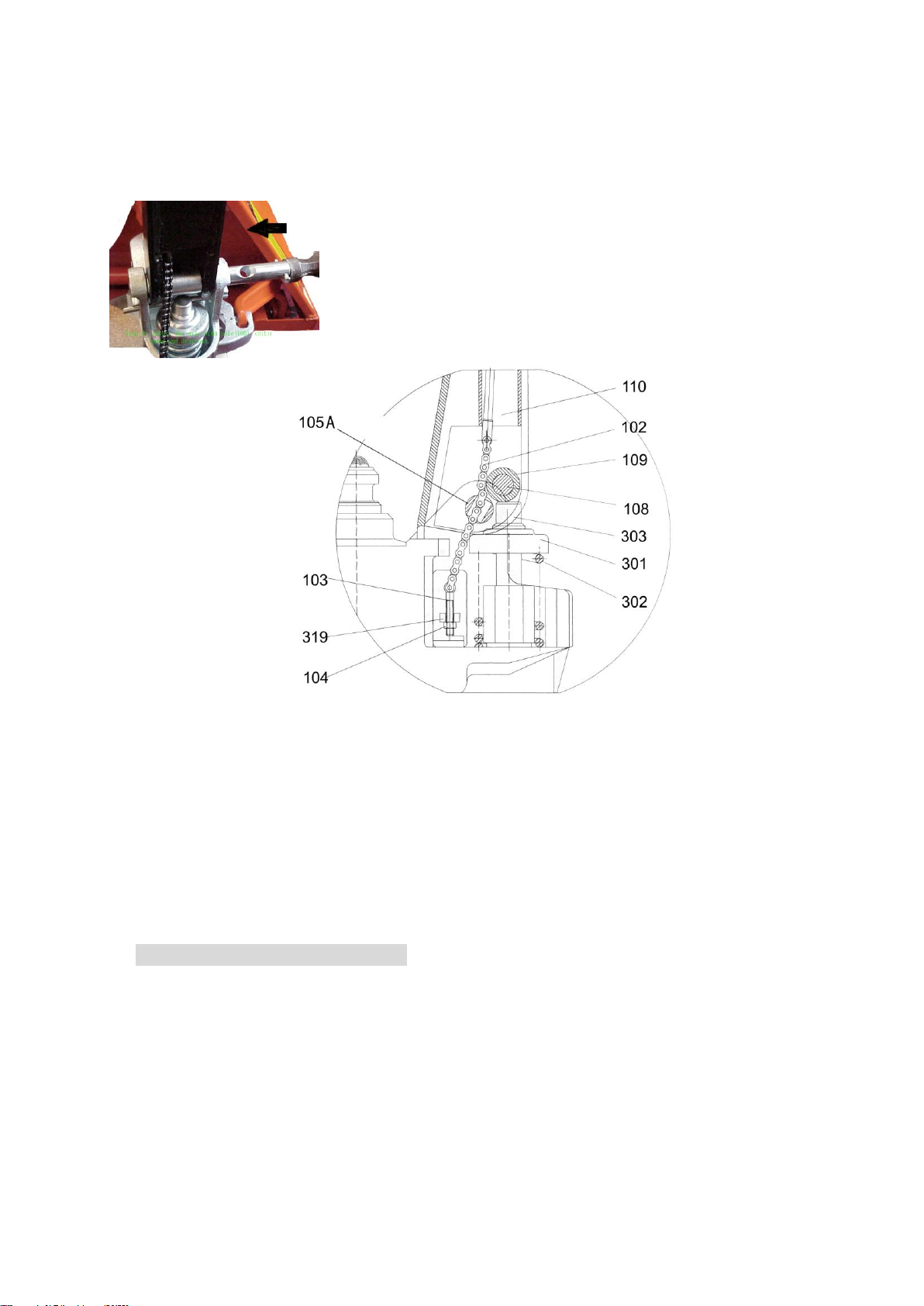
3.2 If the forks descend while pumping in the DRIVE position, turn the nut(104) or screw(318)
counter-clockwise until the forks do not lower.
3.3 If the forks do not descent when the control handle (117 or 120G) is in the LOWER position, turn
the nut(104) or screw (318) clockwise until raising the control handle(117 or 120G) lowers the
forks. Then check the DRIVE position according to item 3.1 and 3.2 to be sure the nut (104) and
screw(318) is in the proper position.
3.4 If the forks do not elevate while pumping in the RAISE position, turn the nut (104) or screw (318)
counter-clockwise until the forks elevate while pumping in the RAISE position. Then check the
LOWER and DRIVE position according to item 3.1, 3.2 and item 3.3.
4. MAINTENANCE
The pallet truck is largely maintenance-free.
4.1 OIL
Please check the oil level every six months. The oil can be hydraulic oil: ISO VG32, its viscosity
should be 30cSt at 400C, total volume is about 0.4lt.
4.2 TO BANISH THE AIR
The air may come into the hydraulic oil because of transportation or pump in upset position. It can
cause that the forks do not elevate while pumping in the RAISE position. The air can been removed
in the following way: let the control handle (117 or 120G) on the LOWER position, then move the
draw-bar up and down for several times.
4.3 DAILY CHECK AND MAINTENANCE
Daily check of the pallet truck can limit wear as much as possible. Special attention should be paid
to the wheels, the axles, as thread, rags, etc. It may block the wheels. The forks should be unloaded
and lowered in the lowest position when the job is over.
4.4 LUBRICATION
All bearings and shafts are provided with long-life grease at the factory. You only need provide with
long-life grease at monthly intervals or after each time the truck is cleaned thoroughly to the
lubrication points.
5 GUIDE TO SAFETY OPERATION
5.1 Operator should read all warning signs and instructions here and on the pallet truck before using
this truck.
5.2 Do not use on a slopping ground.
5.3 Do not operate a pallet truck unless you are familiar with it and have been trained or authorized
to do so.
5.4 Do not operate a pallet truck unless you have checked its condition. Give special attention to the
wheels or rollers, the draw-bar unit, the fork unit, the lever plate, etc. .
5.5 To pull the truck, always move the control handle into the drive position. This makes the
draw-bar easier to move and depressurizes the pump section of the hydraulics. This preserves
the hydraulic seals and the valve components.Along service life can be expected.
5.6 Do not take up any people on the pallet truck.
5.7 The operator had better take on gloves for labor protecting.
5.8 When the goods have been transported, all people should be away from the forks for 600mm.
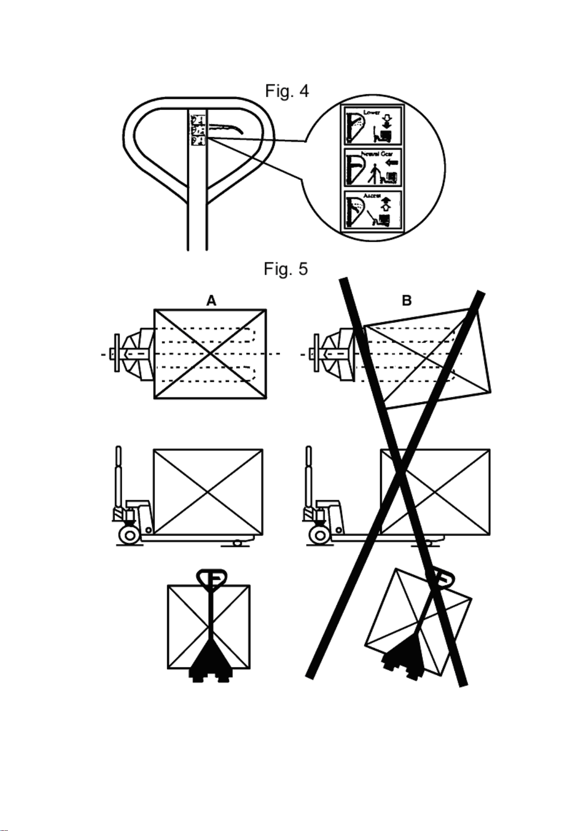
5.9 Do not load goods like fig. 5/B .
5.10 Do not load over maximum capacity.
5.11 At others special condition or place, the operator should be carefully to operate the pallet truck.

4
6. TROUBLES SHOOTING
No
Trouble
Clause
Fixing Methods
1
The forks can
not be up the
max. height.
-The hydraulic oil is not enough.
-Pour in the oil.
2
The forks can
not be lifted
up.
-Without hydraulic oil.
-The oil has impurities.
-The nut (104) is too high, keep the
pumping valve open.
-Air come into the hydraulic oil.
-Fill in the oil.
-Change the oil.
-Adjust the nut(104) or screw (318)
(see item 3.4)
-Banish the air.(see item 4.2)
3
The forks can
not be
descended.
-The piston rod(328) or pump (322) is
deformed resulting from partial loading
slanting to one side or over-loading.
-The fork was kept in the high position
for long time with piston rod bared to
arise in rusting and jamming of the
rod.
-The adjusting nut (104) or screw (318)
is not in correct position.
-Replace the piston rod (328) or
pump (322).
-Keeping the fork in the lowest
position if not using, and pay more
attention to lubricate the rod.
-Adjust the nut (104) or screw (318)
(see item 3.3)
4
Leaks
-Sealing parts worn or damaged.
-Some part cracked or worn into small.
-Replace with the new one.
5
The fork
descends
without the
release valve
worked.
-The impurities in the oil cause the
release valve to be unable to close
tight.
-Some parts of hydraulic system is
cracked or bored.
-Air come into the oil.
-Sealing parts worn or damaged.
-The adjusting nut (104) or screw (318)
is not in the correct position.
-Replace with new oil.
-Inspect and replace the waste
parts.
-Banish the air. (See item 4.2)
-Replace with the new one.
-Adjusting the nut (104) or screw
(318). (See item 3.2)
NOTE: DO NOT ATTEMP TO REPAIR THE PALLET TRUCK UNLESS YOU ARE TRAINED AND
AUTHORIZED TO DO SO.

5

6
LIST of DRAW-BAR
No.
Description
Qty.
Remark
101
18E101
Release Rod
1
102
18E102+103
Chain
1
103
Adjusting Bolt
1
104
18E104
Adjusting Nut
1
105A
18E105
Axle with Hole
1
106
18E106
Elastic Pin
2
107
18E107
Bushing
2
108
18E108
Roller Pin
1
109
18E109
Pressure Roller
1
109A
18E109A
Bushing
1
111
18E111
Stop Rubber
1
112
18E112
Elastic Pin
1
113
18E113
Blade Spring
1
114
18E114
Spring
1
115
18E115
Elastic Pin
1
116
18E116
Elastic Pin
1
117
18E117
Control Handle
1
118
18E118
Roller
1
119
18E119
Elastic Pin
1
121
18E121
Pull Board
1
122
18E122
Pin
1
18E1
Complete Handle Assembly
1

7

8
LIST OF FORK FRAME
No.
Description
Qty.
Remark
202
18E202
Elastic Pin
1
For Type A
202G
18E202G
Bolt
1
For Type G
203
18E203
Rock - Arm
1
204
18E204
Bushing
2
205
18E205
Shaft
2
206
18E206
Bushing
4
207
18E207
Bushing
2
208
18E208
Retaining Ring
2
210
18E210
Pin
2
209
18E209
Joint
2
For Type C
211
18E211
Nut
2
212
18E212
Pushing Rod
2
B209
18E209B
Joint
2
For Type B
B211
18E211B
Nut
2
B212
18E212B
Pushing Rod
2
213
18E213
Retaining Ring
2
214
18E214
Shaft
1
214BG
18E214BG
Shaft
1
For Type BG
216
18E216
Shaft
2
217
18E217
Intermediate Roller
4
218
18E218
Extending Roller
2
219
18E219
Elastic Pin
2
220
18E220
Elastic Pin
4
221
18E221
Shaft
2
222
18E222
Frame of Roller
2
223*
18E223
Shaft
4
For Type E
224*
18E224
Tandem Mounting with Pin
2
228*
18E228
Tandem Mounting
2
229*
18E229
Spring Washer
4
230
18E230
Elastic Pin
8 or 2
223DA*
18E223DA
Shaft for Roller
4
For Type D
224DA*
18E224DA
Linking Plate
4
230D
18E230D
Elastic Pin
8 or 2
225
18E225
Washer
8 or 4
226
18E226
Bearing
8 or 4
227*
18E227NT-7
Nylon Loading Roller (Tandem)
4
227*
18E227PT-7
Poly Loading Roller (Tandem)
4
231
18E231
Bolt
2
232
18E232
Enter Roller
2
233
18E233
Locking Nut
2
234#
18E234P-7
PU load wheel (Single)
2
234#
18E234N-7
Nylon load wheel (Single)
2
235#
18E235
Shaft for Roller
2
236
18E236
Washer
2
237
18E237
Grease Cup
1
18E155
Seal Kit
1

9
NOTE: *-- For double wheel; #-- For single wheel

10
Type Y hydraulic pump
No.
Mobile #
Description
Qty.
Remark
301
18E301
Spring Cap
1
302
18E302
Spring
1
303
18E303
Pump Piston
1
304
18E304
Dust Ring
1
305
18E305
Seal
1
306
18E306
Dust Cover
2
307
18E307
Locking Ring
2
308
18E308
Washer
2
309
18E309
Bearing
4
310
18E310P-1
PU steering wheel
2
310
18E310R-1
Rubber steering wheel
2
310
18E310N-1
Nylon steering wheel
2
311
18E311
Elastic Pin
1
312
18E312
Elastic Pin
2
313
18E313
Thrust Plate
1
314
18E314
Retaining Ring
1
315
18E315
Bearing
1
316
18E316
Shaft of loading Wheel
1
317
18E317
Nut
1
318
18E318
Screw
1
319
18E319
Lever Plate
1
320
18E320
Elastic Pin
1
321
18E321
Valve Cartridge
1
323Y
18E323Y
Seal Washer
1
Only Type Y Pump
324Y
18E324Y
Screw Plug
1
325
18E325
Seal
1
326
18E326
O –Ring
1
327
18E327
Dust Ring
1
328
18E328
Piston Rod
1
329
18E329
Steel Ball
1
330Y
18E330Y
Screw Plug
1
331Y
18E331Y
O - Ring
1
Only Type Y Pump
332Y
18E332Y
Bolt
1
333Y
18E333Y
Spring
1
334Y
18E334Y
Spindle of Safety Valve
1
335
18E335Y
Grease Cup
1
336
18E336
Cylinder
1
337
18E337
Cover of Bearing
1
340Y
18E340Y
Cover with Screw
1
341Y
18E341Y
O - Ring
1
Only Type Y Pump
18E0
Complete Pump Assembly
1

11

12
QUICK LIFTING HYDRAULIC PUMP
No
Mobile #
Description
Qty.
Remark
301F
18E301F
Spring Cap
1
302F
18E302F
Spring
1
303F
18E303F
Pump Piston for Quick Lifting
1
322FA
18E2
Pump for Quick Lifting
1
335F
18E335F
Pin
1
336F
18E336F
Cap of Pin
1
337F
18E337F
O - Ring
1
338F
18E338F
Pump Cylinder
1

13
version number:111201
Load Backrest
No
Mobile #
Description
Qty.
Remark
1
18ELBR1
Bolt
2
2
18ELBR2
Spring Washer
2
3
18ELBR3
Washer
2
4
18ELBR4
Load Back Rest
1

14
MOBILE INDUSTRIES INC.
3610 Mavis Road, Mississauga, Ontario, L5C 1W2, CANADA
Tel: (905) 279-5370 Toll-free: 800-527-4612 Fax: (905) 279-7384 Toll-free: 800-952-5097
E-mail: intl@mobilept.com Website: www.mobilept.com
Table of contents
Other Mobile Truck manuals