SECTION 1 – Mount Large Components
Stripping wire, tinning wire and soldering. Throughout these instructions you will be told to strip
and tin a length of wire numerous times. Unless noted otherwise, cut the wire to the length stated in
the instructions. Then strip ¼” of insulation off each end. Twist each end of the stranded wire, and
apply a small amount of solder to each end (i.e. tin the wire ends). This will prevent the stranded
wire from fraying and will make the final soldering much easier.
Please refer to DRAWING 1 and DRAWING 2.
Orient the enclosure with the three 9/32" holes on top.
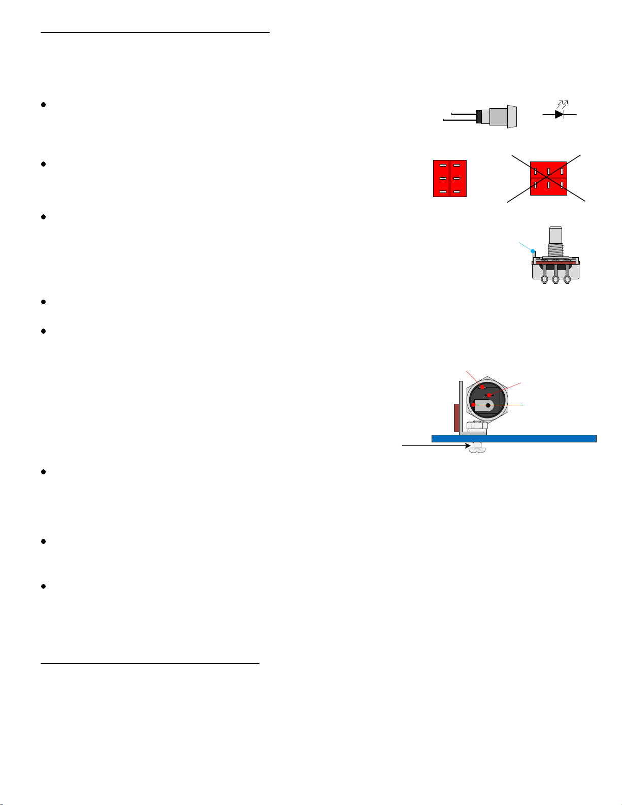
Mount the DC power jack in the 15/32" hole on the left side of the enclosure. Orient its solder
lugs so that the center-pin lug is facing the bottom side of the enclosure.
Mount the input jack in the 3/8" hole on the left side of the enclosure with the hardware provided.
The washer goes under the nut on the outside of the enclosure. Make sure the center solder lug
of the input jack is facing up. Correct positioning of the jack makes soldering the connections
easier.
Mount the output jack in the 3/8" hole on the right side of the enclosure. Make sure the two
solder lugs are in their most upright position before tightening the nut.
Mount the footswitch in the 15/32" hole in the center of the enclosure. The nylon washer goes
under the mounting nut on the outside of the enclosure. Then the lock washer mounts on the
inside between the enclosure surface and the other nut. Make sure that the footswitch is
oriented to match DRAWING 2.
SECTION 2 – Wire Large Components
Please refer to DRAWING 3.
7
Mount the LED and bezel holder in the ¼” hole below the middle
9/32" hole. Align the LED leads so that the anode (positive lead) is
closer to the left side of the enclosure as shown in Drawing 2.
The Anode (+) side of the LED is
indicated by a slightly longer lead
and/or a positive sign.
LED Physical
Representation
+
-
+-
LED Schematic
Symbol
anode cathode
Mount the toggle switch in the ¼" hole between the middle and
right side of the enclosure. Make sure its solder lugs are oriented
as shown in Drawing 2.
Correct Orientation Incorrect Orientation
Bend back and remove the alignment tab on the top of each potentiometer using a pair of
pliers before mounting the pots so that they can mount flush against the enclosure surface.
Alignment
Tab
Mount the three pots in their respective 9/32" holes as shown in
Drawing 2.
Using the 6 screws, nuts and lock washers, fasten the 3 terminal strips to match Drawing 2.
You might find it difficult to fit the nut for the DC power jack on to the power
jack due to the proximity of the two terminal strip screws. If so, one way to
make it easier would be to loosen those screws temporarily so that there is
more space for the power jack's nut to fit through. CENTER-PIN LUG
POSITIVE-SWITCH
LUG
POSITIVE LUG
Temporarily loosen screw
to fasten Power Jack nut