7
SECTION 2 – Mount Potent ometers and Footsw tch
1) Mount the two 250K potentiometers in the 3/8" holes at the top of the enclosure using hardware
provided.
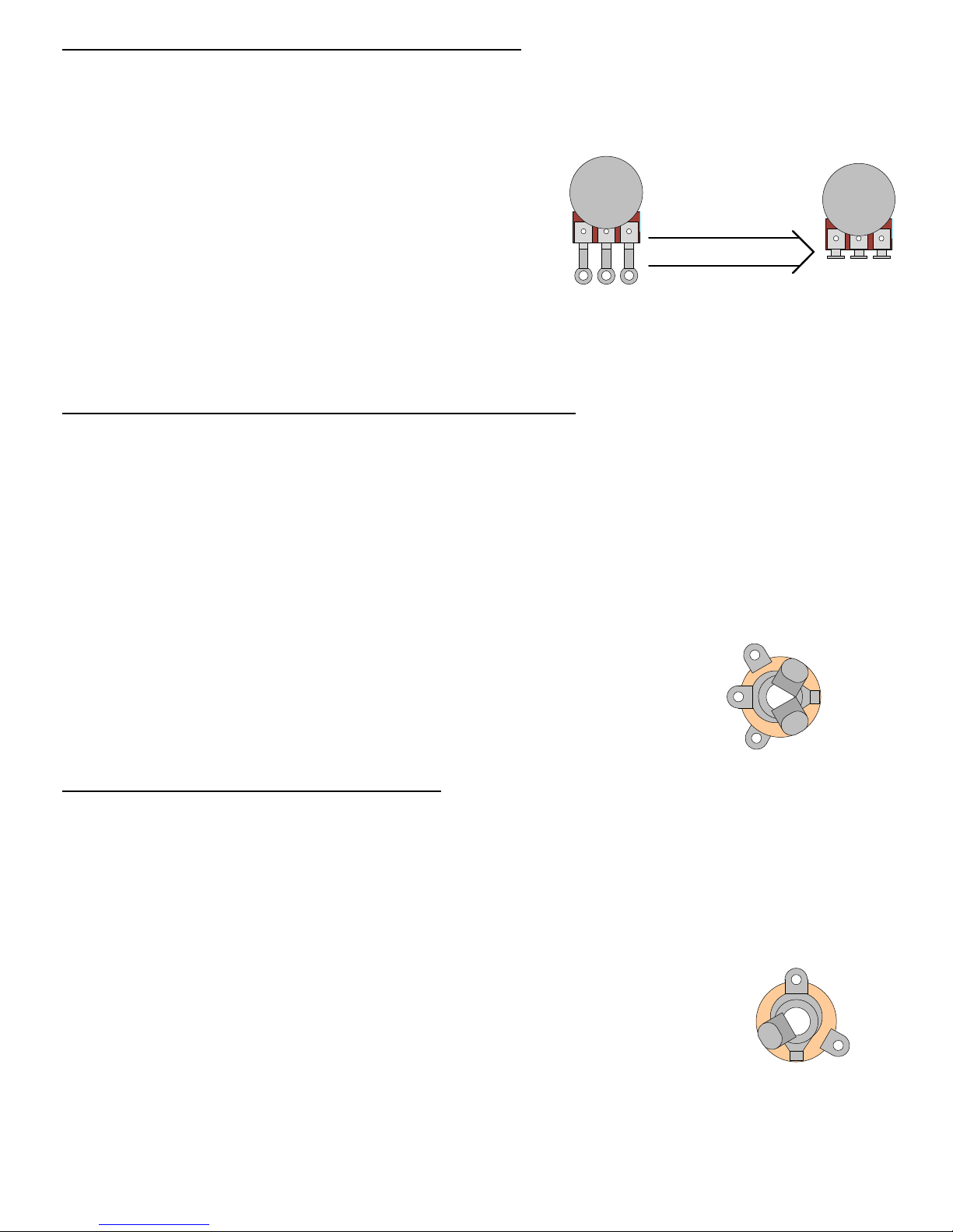
emove nut and flat washer from potentiometers and
place large lock washers (S-HLW38) over shaft of each
pot before inserting them through their mounting holes.
Fasten nut over flat washer and tighten. 1 2 3
1 2 3
Before mounting, gently
bend the pot lugs back so
they are pointing straight
up when mounted.
2) Mount the DPDT footswitch in the ½” hole with its solder lugs oriented as in the drawing.
(The top hex nut and large plastic washer should be fastened on the outside of the box).
Please refer to DRAWING 3.
SECTION 3 – Mount and Connect Rema n ng Components
1) Connect the loose ends of the two diodes to output pot lug “1”. Do not solder.
2) Connect one of the 0.1µF capacitors to output pot lug “1” and terminal #5 of the terminal strip.
Solder all connections at output pot lug “1” and terminal #5 now.
3) Connect the other 0.1µF capacitor to terminal #4 and to both lugs “2” and “3” of the distortion pot.
Solder all connections at terminals #3, #4, #5 and distortion pot lugs “2” and “3” now.
4) Locate the battery clip. Cut 1 ½” length off the ends of each
lead and discard (or save for other projects). Connect the black
lead to the “ring” lug of the input jack. Connect the red lead to
terminal #2 of the terminal strip. Solder these connections now.
Please refer to DRAWING 4.
SECTION 4 – W re Rema n ng Connect ons
1) Strip and tin a 1 ½” piece of wire connect footswitch lugs “3” and “6”.
2) Strip and tin a 1" piece of wire and connect the input jack “tip” lug to the footswitch lug “2”.
3) Strip and tin a 3 ½” piece of wire and connect footswitch lug “1” to distortion pot lug “1”.
4) Strip and tin a 1 ¾” piece of wire and connect the output jack “ground” lug to
output pot lug “3”.
GROUND LUG
TIP LUG
5) Strip and tin a 1 ¼” piece of wire and connect the output jack “tip” lug to
footswitch lug “5”.
6) Strip and tin a 3 ½” piece of wire and connect the output pot lug “2” to footswitch lug “4”.
F n sh t off by double-check ng all of your connect ons, connect and nsert a 9V battery (w th nsulat on), screw
the l d on and fasten the knobs to both pot shafts.
RING LUG
SLEEVE LUG
TIP LUG
Leave the area behind the footswitch free from obstruction because it will be a tight fit for the 9V battery back there.