Moda Light FLATFLEX HCRI INTERIOR User manual

FLATFLEX HCRI INTERIOR
INSTALLATION
955 White Drive Las Vegas, NV 89119 | T: 702 407 7775
F: 702 407 7773 | www.modalight.com | © 2023
Due to continuous improvements and innovations, specifications may change without notice.
Please refer to our website for current technical data. These figures are provided as a guideline
only and may vary with differing power supplies and installations. All rights reserved. E&OE.
1 / 81 / 8VDC 01/4/2023
2
3
Verify electrical plan and ensure all hardware is present
Verificar plan electrico y verifique que todo el equipo esté presente
Vérifier le plan électrique et assurer que tout le matériel est présent
Compatible driver list
Lista de controladores compatibles
Liste des pilotes compatibles
1Must be installed by a qualified electrician in accordance with all national and local electrical and construction codes and
regulations by a person familiar with the construction and operation of the product and the hazards involved. Failure to comply
with the following installation instructions will void the warranty and may result in serious injury or possible death. Ensure power
is off before installation, verify electrical plan first and read all installation instructions prior to installation. With the constant
development of our products please check our website (www.modalight.com) for any possible changes to the installation of this
product.
Debe ser instalado por un electricista calificado de acuerdo con todos los códigos y reglamentos eléctricos y de construcción nacionales y locales, por una
persona familiarizada con la construcción y el funcionamiento del producto y los riesgos involucrados. El incumplimiento de las siguientes instrucciones de
instalación anulará la garantía y puede provocar lesiones graves o la muerte. Asegúrese de que la energía esté apagada antes de la instalación, verifique
primero el plan eléctrico y lea todas las instrucciones de instalación antes de instalar. Con el constante desarrollo de nuestros productos, visite nuestro website
(www.modalight.com) para todos posibles cambios en la instalación de este producto.
Doit être installé par un électricien qualifié conformément à tous les codes et réglementations électriques et de construction nationaux et locaux par une
personne connaissant bien la construction et le fonctionnement du produit et les risques encourus. Le non-respect des instructions d’installation suivantes
annulera la garantie et pourrait entraîner des blessures graves ou la mort éventuelle. Assurez-vous que l’alimentation est coupée avant l’installation, vérifiez
d’abord le plan électrique et lisez toutes les instructions d’installation avant l’installation. Avec le développement constant de nos produits s’il vous plaît consulter
notre site web (www.modalight.com) pour toutes les modifications possibles à l’installation de ce produit.
DRY LOCATION INSTALL
INSTALACIÓN DE LUGARES SECOS
INSTALLATION EMPLACEMENT SEC
Max Continuous Run: 32’ 9 3/4” (10m)
Continuidad Máxima: 32’ 9 3/4” (10m)
Run Continue Max: 32’ 9 3/4” (10m)
!
Non Dimming Voltage Range Wattage IP Rating Max Load
MP17 100-277V AC 150W IP20 40ft
0-10V Dimming Voltage Range Wattage IP Rating Max Load
MP06 347V AC 60W IP20 16ft
MP19N 100-277V AC 60W
IP20
16ft
MP87 100-277V AC 100W
IP20
26ft
MP89 100-277V AC 150W
IP20
40ft
10’ Leader Cable Jumper Cable End Cap

FLATFLEX HCRI INTERIOR
INSTALLATION
955 White Drive Las Vegas, NV 89119 | T: 702 407 7775
F: 702 407 7773 | www.modalight.com | © 2023
Due to continuous improvements and innovations, specifications may change without notice.
Please refer to our website for current technical data. These figures are provided as a guideline
only and may vary with differing power supplies and installations. All rights reserved. E&OE.
2 / 82 / 8VDC 01/4/2023
5Wiring
Cablería
Cables
UL / cUL Non-dimmingUL / cUL Non-dimming
UL / cUL ELV DimmingUL / cUL ELV Dimming
WIRING LEGENDWIRING LEGEND
24V DC Driver Primary Side24V DC Driver Primary Side
Black AC Power PositiveAC Power Positive
White AC Power NegativeAC Power Negative
GreenGreen AC Power GroundAC Power Ground
24V DC Driver Secondary Side24V DC Driver Secondary Side
Red DC Power PositiveDC Power Positive
Black DC Power NegativeDC Power Negative
PurplePurple 0-10V Data Positive0-10V Data Positive
NegativeNegative 0-10V Data Negative0-10V Data Negative
DRIVER
DRIVER
A
B C
C
A C
24V DC
Driver Moda
Tape Light
B
100-277V
AC
24V DC
Driver
0-10V
Dimmer
100-277V
AC 24V DC
Driver
4
Minimum bend radius for FPCB is 2” (50mm).
Damage will occur if strips are bent at sharp angles.
Curvatura mínima para FPCB es de 2“ (50mm).
Daño se producirá si las tiras se doblan en ángulos agudos.
Minimum de courbure pour FPCB est de 2“ (50mm).
Les dommages se produira si les bandes sont pliés à angles vifs.
!
Flatflex 3’
Xtrusion®
Mounting
Clips
Press Flatflex®firmly into mounted clips or Xtrusion®
Atornille los clips de montaje . Espacios recomendados entre los clips de montaje es 1 cada pie.
Vissez clips de montage . espacement recommandé pour les clips de montage 1 chaque pied.

FLATFLEX HCRI INTERIOR
INSTALLATION
955 White Drive Las Vegas, NV 89119 | T: 702 407 7775
F: 702 407 7773 | www.modalight.com | © 2023
Due to continuous improvements and innovations, specifications may change without notice.
Please refer to our website for current technical data. These figures are provided as a guideline
only and may vary with differing power supplies and installations. All rights reserved. E&OE.
3 / 83 / 8VDC 01/4/2023
6
7
Field cuttable at designated points
Corte en los puntos designados
Il peut être coupé à des points désignés
Slide PC Sleeve onto FPCB.
Place the anti-skidding clip onto the end of the FPCB.
Anti-skidding clip must wrap tightly. Align the
brim with the bottom cut edge of the FPCB.
Unfold the anti-skidding clip.
Dezlice PC Sleeve en FPCB.
Coloque el clip anti-derrape al final del FPCB.
El clip anti-derrape debe envolver herméticamente. Alinear
el ala con el borde de corte inferior del FPCB.
Despliegue el clip anti-derrape.
Glisser sur PC Sleeve FPCB.
Placez le clip anti-dérapage sur l’extrémité de FPCB. Clip anti-dérapage doit bien envelopper. Alignez le
ras bord avec le bord coupé en bas de la FPCB.
Déplier le clip anti-dérapage.
Leader cable connection
Conexión de cable de poder
Connexion du cordon d’alimentation

FLATFLEX HCRI INTERIOR
INSTALLATION
955 White Drive Las Vegas, NV 89119 | T: 702 407 7775
F: 702 407 7773 | www.modalight.com | © 2023
Due to continuous improvements and innovations, specifications may change without notice.
Please refer to our website for current technical data. These figures are provided as a guideline
only and may vary with differing power supplies and installations. All rights reserved. E&OE.
4 / 84 / 8VDC 01/4/2023
Align leader cable with FPCB. Insert the leader cable onto the FPCB.
Alinie cable líder con FPCB. Inserte cable líder en FPCB.
Alignez chef de câble avec FPCB. Insérez le câble de chef de file dans le FPCB.
Align U-Steel plate at the bottom with leader cable and anti-skidding clip. Press down leader cable and anti-skidding clip onto U-Steel plate.
Alinie placa U-Steel en la parte inferior con cable líder y clip anti-derrape. Presione cable líder y clip anti-derrape con la placa U-Steel.
Aligner la plaque U-Steel au fond avec câble de liaison et un clip anti-dérapage. Appuyez câble leader et pince anti-dérapage sur la plaque U-Steel.
7A
Do not extend leader cable beyond 10’.
No extienda el cable lider más de 10’.
N’étendez pas câble leader au-delà de 10’.
!
Slide back PC Sleeve. Make sure PC Sleeve snaps in front of leader cable.
CLICK!
Dezlice PC Sleeve hacia atrás. Asegurece que el PC Sleeve connecte delante de cable líder.
Repousser PC Sleeve. Assurez-vous que PC Sleeve se mette en face de câble de leader.

FLATFLEX HCRI INTERIOR
INSTALLATION
955 White Drive Las Vegas, NV 89119 | T: 702 407 7775
F: 702 407 7773 | www.modalight.com | © 2023
Due to continuous improvements and innovations, specifications may change without notice.
Please refer to our website for current technical data. These figures are provided as a guideline
only and may vary with differing power supplies and installations. All rights reserved. E&OE.
5 / 85 / 8VDC 01/4/2023
8Install end cap
Instalar tapa de extremo
Installer le capuchon
Slide PC Sleeve onto FPCB.
Dezlice PC Sleeve
Faites glisser PC Sleeve sur FPCB.
Unfold the anti-skidding clip.
Despliegue el clip anti-derrape.
Déplier le clip anti-dérapage.
Place the anti-skidding clip onto the end of the FPCB.
Anti-skidding clip must wrap tightly. Align the
brim with the bottom cut edge of the FPCB.
Coloque el clip anti-derrape al final del FPCB
El clip anti-derrape debe envolver herméticamente. Alinear
el ala con el borde de corte inferior de la FPCB.
Placez le clip anti-dérapage sur l’extrémité de l’FPCB. Clip anti-dérapage doit bien envelopper. Alignez le
ras bord avec le bord coupé en bas de la FPCB.
Align end cap with FPCB. Insert end cap onto the FPCB.
Alinie tapa final con FPCB. Inserte tapa final en FPCB.
Alignez embout avec FPCB. Insérer bouchon sur le FPCB.
Align U-Steel plate at the bottom with end cap and anti-skidding clip. Press down end cap and anti-skidding clip onto U-Steel plate.
Alinie U-Steel placa en la parte inferior con tapa final y el clip anti-derrape. Presione tapa final y el clip anti-derrape con la placa U-Steel.
Aligner la plaque U-Steel au fond avec capuchon et le clip anti-dérapage. Appuyez capuchon et le clip anti-dérapage sur la plaque U-Steel.

FLATFLEX HCRI INTERIOR
INSTALLATION
955 White Drive Las Vegas, NV 89119 | T: 702 407 7775
F: 702 407 7773 | www.modalight.com | © 2023
Due to continuous improvements and innovations, specifications may change without notice.
Please refer to our website for current technical data. These figures are provided as a guideline
only and may vary with differing power supplies and installations. All rights reserved. E&OE.
6 / 86 / 8VDC 01/4/2023
9
Leader cable connection Jumper cable connection
Available connections
Conexiones disponibles
Connexions disponibles
CLICK!
Slide back PC Sleeve. Make sure PC Sleeve snaps in front of end cap.
Dezlice PC Sleeve hacia atrás. Asegurece que el PC Sleeve connecte delante de la tapa final.
Repousser PC Sleeve. Assurez-vous que PC Sleeve mette en face du capuchon.

INSTALLATION
955 White Drive Las Vegas, NV 89119 | T: 702 407 7775
F: 702 407 7773 | www.modalight.com | © 2023
Due to continuous improvements and innovations, specifications may change without notice.
Please refer to our website for current technical data. These figures are provided as a guideline
only and may vary with differing power supplies and installations. All rights reserved. E&OE.
7 / 87 / 8VDC 01/4/2023
FIXTURE SKU
Flatflex - IP20 Dry Location 24V DC Black Finish 2700K HCRI 150ft FF-B-2700K-150FT
Flatflex - IP20 Dry Location 24V DC Black Finish 3000K HCRI 150ft FF-B-3000K-150FT
Flatflex - IP20 Dry Location 24V DC Black Finish 4000K HCRI 150ft FF-B-4000K-150FT
PRODUCT: SUMMARY
POWER SKU
24V DC Driver - 100-277V AC Input - Non-Dimmable - 150W - IP20 MP17
24V DC Driver - 347V AC Input - 0-10V Dimmable - 60W - IP20 MP06
24V DC Driver - 100-277V AC Input - 0-10V Dimmable - 60W - IP20 MP19N
24V DC Driver - 100-277V AC Input - 0-10V Dimmable - 100W - IP20 MP87
24V DC Driver - 100-277V AC Input - 0-10V Dimmable - 150W - IP20 MP89
ACCESSORIES SKU
Flatflex Leader Cable S2 White 5ft FF-LDR-CBL-S2-W-5FT
Flatflex In-Line Connector White FF-ILC-W
Flatflex Jumper Cable White 1ft FF-JMP-CBL-W-1FT
Flatflex Terminator White (10 Pack) FF-T-W
Flatflex Clip (10 Pack) FF-CLP
Flatflex Xtrusion 3ft FF-XTR-3FT

FLATFLEX HCRI INTERIOR
INSTALLATION
955 White Drive Las Vegas, NV 89119 | T: 702 407 7775
F: 702 407 7773 | www.modalight.com | © 2023
Due to continuous improvements and innovations, specifications may change without notice.
Please refer to our website for current technical data. These figures are provided as a guideline
only and may vary with differing power supplies and installations. All rights reserved. E&OE.
8 / 88 / 8VDC 01/4/2023
!Do not attempt to install or use the product until
installation is fully read and understood!
No intente instalar o utilizar el producto sin antes leer y comprender las
instrucciones!
Ne tentez pas d’installer ou d’utiliser le produit jusqu’à ce que
l’installation est entièrement lu et compris!
!Do not use the product if FPCB or power
cables are damaged!
No utilize el producto si el FPCB o cables de energía estan defectuosos!
Ne pas utiliser le produit si le FPCB ou alimentation défectueux est des
câbles!
!Do not use currents or voltages of any kind that
do not fit under the product’s requirements!
Por favor no utilice corrientes o voltajes que no sean los que se especifican
para los productos!
S’il vous plaît ne pas utiliser des courants ou des tensions autres que celles
spécifiées pour la lampe!
!Make sure that power or cable is completely off or
disconnected before connecting or disconnecting the
product!
Por favor asegurese que el suministro de electricidad este apagado y cables
estén desconectados antes de conectar o desconectar los productos!
Faire S’il vous plaît assurer que l’alimentation et les câbles d’électricité sont
hors tension et débranché avant de brancher ou de débrancher lampes!
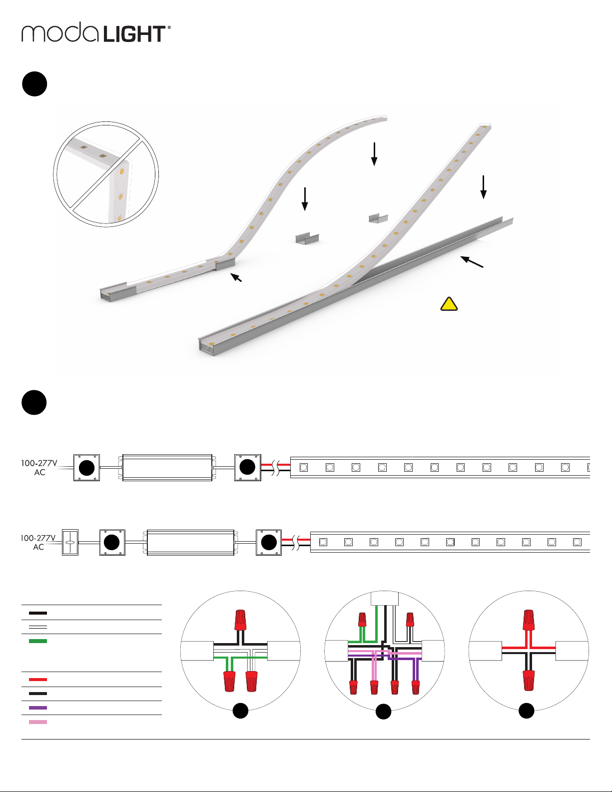
!The maximum recommended distance from
driver to the product is 10’. Any distance beyond
that is not recommended by Moda, and any
damage caused by overextending leads will void
warranty!
La distancia maxima recomendada desde driver a producto es de 10’.
Cualquier distancia más ayá no es recomendada por Moda, cualquier daño
causado por sobre extender cables anulará la garantía!
La distance maximale recommandée du pilote du produit est de 10‘. Toute
distance au-delà est pas recommandé par Moda, et tout dommage causé
par plus de l’extension des pistes annulera la garantie!
!Do not bend product beyond the minimum
bend radius listed on the installation guide!
No doble producto más allá del radio de curvatura mínima que aparece
en la guía de instalación!
Ne pas plier le produit au-delà du rayon de lit minimum indiqué sur le guide
d’installation!
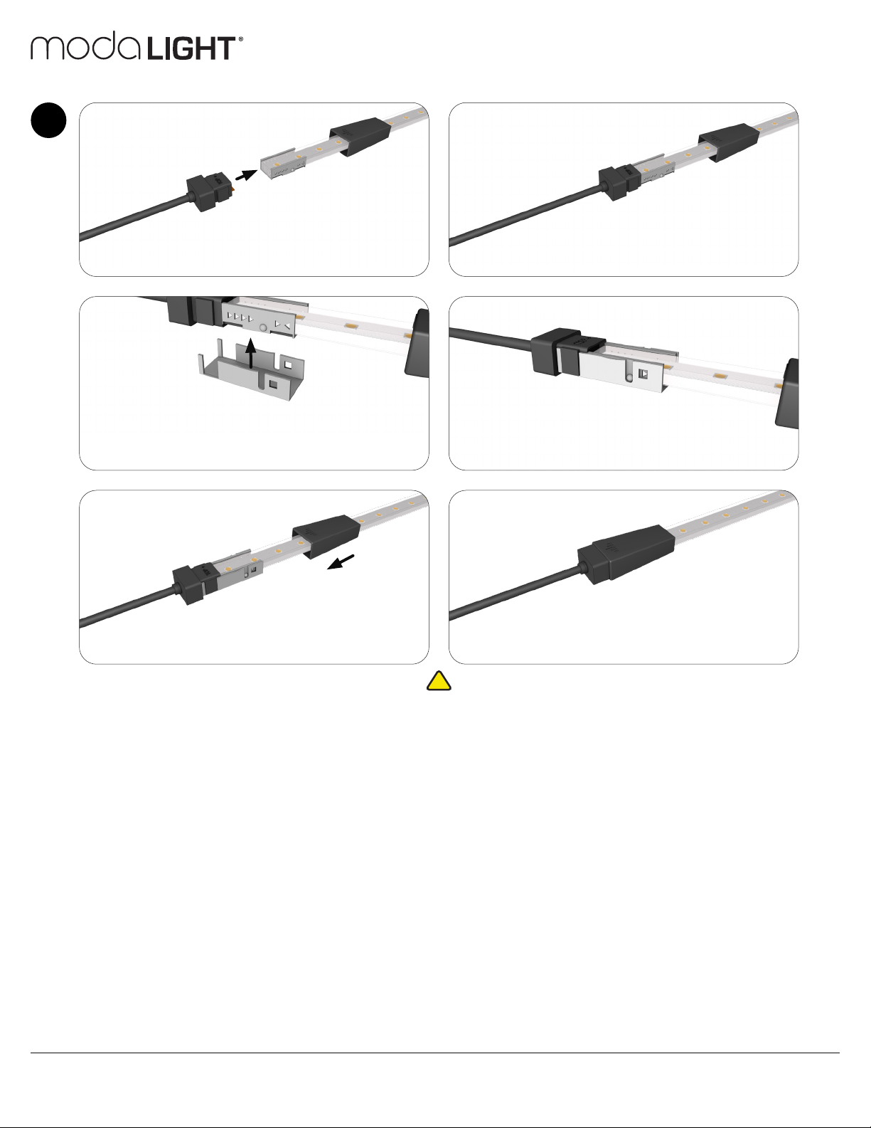
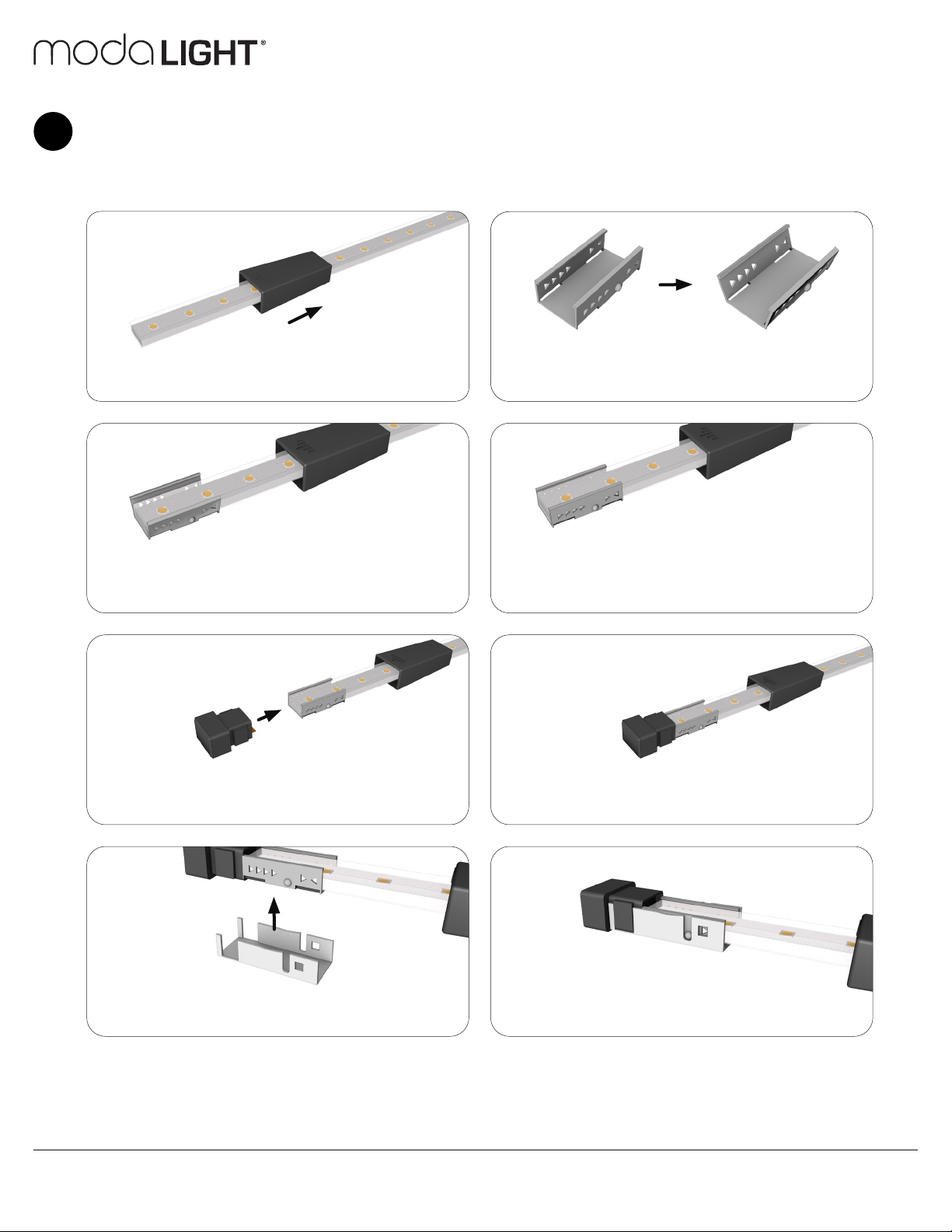
!Please make sure all connections are completely
pushed in before powering on to avoid electrical
arching!
Por favor asegúrese de que todas las conexiones estén completamente intro-
ducidas antes de encender para evitar arco electrico!
Font S’il vous plaît que toutes les connexions sont complètement enfoncés
avant d’allumer pour éviter arquées électrique!
!Do not coat the product in paint! This will ruin
the product and void warranty!
No cubra el producto en pintura! Esto va a arruinar el producto y anular la
garantía!
Ne pas enduire le produit dans la peinture! Cela va ruiner le produit et
annuler la garantie!
!Please make sure to install in accordance with
the local code!
Por favor asegúrese de instalar de acuerdo con el código local!
Faire S’il vous plaît veillez à installer en conformité avec le code local!
!Please do not cut the product anywhere other
than the designated cutting points!
Por favor, no corte el producto en otro lugar que no sea en los puntos de
corte designados!
S’il vous plaît ne pas couper le produit ailleurs que les points de coupe
désignés!
!Please do not power product while it is on the
reel!
Por favor, no encender producto mientras esté en el carrete!
S’il vous plaît ne pas produit de puissance alors qu’il est sur la bobine!
!Do not stare into beam.
No mire fijamente la luz.
Ne pas regarder le faisceau.
!Only use Moda Drivers which are listed as
compatible drivers.
Solo utilize Moda Drivers que están enlistados como drivers compatibles.
Utilisez uniquement Moda Drivers qui sont répertoriés comme pilotes com-
patibles .
!Be careful not to stand on product during
installation.
Tenga cuidado de no pisar el producto durante instalación.
Veillez à ne pas se tenir sur le produit lors de l’installation.
This manual suits for next models
3
Table of contents
Other Moda Light Lighting Equipment manuals
Popular Lighting Equipment manuals by other brands

Stahl
Stahl 6470/2 Series manual

California Sunbounce
California Sunbounce MINI operating instructions

Panlux
Panlux SVORKOVNICE IP68 T quick start guide

Vestil
Vestil SBM Series instruction manual

Armacost Lighting
Armacost Lighting RibbonFlex PRO manual

Larson Electronics
Larson Electronics VPLHL-7WLED-PC-GR30 instruction manual