ModelCraft 22 52 23 User manual

Bedienungsanleitung
Version 06/13
Dieselmotor-Geräuschmodul-Baustein
Best.-Nr. 22 52 23
Bestimmungsgemäße Verwendung
Das Produkt dient zur Erzeugung eines Dieselmotor-Geräusches in dafür geeigneten Model-
len (Fischerkutter oder Trucks). Das elektronische Motorgeräusch kann mit vier Einstellreg-
lern individuell eingestellt werden. Zudem kann mit Hilfe der Spannung des Antriebsmotors
(Kollektormotor) das Dieselmotorgeräusch automatisch der Fahrgeschwindigkeit des Modells
angepasst werden.
Zum Betrieb ist noch ein geeigneter Lautsprecher mit einer Impedanz 4 - 8 Ohm (nicht im
Lieferumfang enthalten, getrennt bestellbar) erforderlich.
Dieses Produkt erfüllt die gesetzlichen, nationalen und europäischen Anforderungen. Alle ent-
haltenen Firmennamen und Produktbezeichnungen sind Warenzeichen der jeweiligen Inhaber.
Alle Rechte vorbehalten.
Lieferumfang
• Geräuschgenerator-Baustein
• Bedienungsanleitung
Sicherheitshinweise
BeiSchäden,diedurchNichtbeachtungdieserBedienungsanleitungverursacht
werden, erlischt die Gewährleistung/Garantie. Für Folgeschäden übernehmen
wir keine Haftung! Bei Sach- oder Personenschäden, die durch unsachgemäße
Handhabung oder Nichtbeachten der Sicherheitshinweise verursacht werden,
übernehmen wir keine Haftung. In solchen Fällen erlischt die Gewährleistung/
Garantie!
a) Allgemein
• AusSicherheits-undZulassungsgründen(CE)istdaseigenmächtigeUmbauenund/oder
Verändern des Produkts nicht gestattet.
• DasProduktistkeinSpielzeug,haltenSieesvonKindernfern.
• DasProduktdarfnichtfeuchtodernasswerden.SchützenSieesvorHitze,Kälte,direkter
Sonneneinstrahlung, Vibrationen, Staub und Schmutz.
• DasProduktdarfnichtinexplosionsgefährdetenBereichenbetriebenwerden.
• LassenSiedasVerpackungsmaterialnichtachtlosliegen,dieseskönntefürKinderzueinem
gefährlichen Spielzeug werden.
• GehenSievorsichtigmitdemProduktum,durchStöße,SchlägeoderdemFallausbereits
geringerHöhewirdesbeschädigt.
b) Anschluss
• DerAnschlussdarfnurinspannungs-/stromlosenZustanderfolgen.
• FürdenAnschlussdesBausatzesisteingeeigneterSchraubendrehererforderlich.
• Achten Sie beim Anschluss der Versorgungsspannung auf die korrekte Polung derAn-
schlussleitungen.EinunsachgemäßausgeführterAnschluss kann zur Beschädigung des
ProduktesundzumVerlustvonGewährleistung/Garantieführen!LassenSiedenAnschluss
im Zweifelsfall von jemand anderem durchführen, der über entsprechende Fachkenntnisse
verfügt.
• DasProduktdarfnurfestmontiertz.B.ineinemdazugeeignetenGehäusebetriebenwer-
den. Wird dies nicht beachtet, so besteht die Gefahr eines Kurschlusses, was den Baustein
zerstört.VerlustvonGewährleistung/Garantie!
• BeachtenSiedieInformationenimAbschnitt„TechnischeDaten“.
DasProduktdarfnurübereinestabilisierteGleichspannungvon6-12V/DCbetriebenwer-
den; der erforderliche Lautsprecher muss eine Impedanz von 4 - 8 Ohm aufweisen.
Anschluss und Inbetriebnahme
Bild 1
•SchließenSieander2poligenKlemme„LS“einenMiniaturlautsprecher(sieheBild1,Pos.1)
an. Der Lautsprecher sollte eine Impedanz von 4 - 8 Ohm aufweisen.
• StellenSiemiteinemgeeignetenSchraubendreherdieSchleiferderEinstellreglerP1-P4
(siehe Bild 1, Pos. 2) in die Mittelstellung. Verwenden Sie dazu einen Kunststoff-Einstell-
schraubendreher, um Kurzschlüsse zu vermeiden.
• SchließenSieandenKlemmen„+“(sieheBild1,Pos.3)und„-“(sieheBild1,Pos.4)die
Versorgungsspannung(6-12V/DC)polungsrichtigan.
Wichtig!
Achten Sie unbedingt auf die richtige Polung, da sonst die Bauteile der Platine zer-
störtwerden.
• BeikorrektemAnschlussmussnachAnschlussderBetriebsspannung bereitseinDiesel-
motorgeräuschausdemangeschlossenenLautsprecherhörbarsein,welchessichmitden
EinstellreglernP3undP4verändernlässt.
• WenndaselektronischeFahrgeräuschgeschwindigkeitsabhängigseinsoll,müssendiebei-
denKlemmen„FS“parallelzumFahrmotor(sieheBild1,Pos.5)angeschlossenwerden.Auf
eine bestimmte Polung der Motoranschlussleitungen ist dabei nicht zu achten.
Beachten Sie:
DerAnschlusseinesFahrmotorsistnurdannmöglich,wennessichbeidemMotor
um einen Gleichstrommotor (Kollektormotor mit 2 Anschlusskabeln) mit entsprechen-
dem Fahrtregler (siehe Bild 1, Pos. 6) handelt.
EinBrushlessmotor(mit3Anschlusskabeln)kannamDieselmotor-Geräuschgenera-
tor nicht angeschlossen werden.
• BringenSiedenFahrmotordesModellsperFernsteuerungaufdiemaximaleDrehzahl.Mit
HilfedesEinstellreglersP1wirdnundasDieselmotorgeräuschebenfallsaufmaximaleDreh-
zahl eingestellt.
• SchaltenSieanschließenddenFahrmotordesModells per Fernsteuerung aus. Mit Hilfe
des Einstellreglers P2 kann nun das Dieselmotorgeräusch auf Leerlauf-Sound eingestellt
werden.
• InAbhängigkeitderFahrgeschwindigkeitändertsichnunauchdaserzeugteDieselmotorge-
räusch aus dem Lautsprecher.
• SolltedasDieselmotorgeräuschunabhängigvonderFahrgeschwindigkeitsein,sowerden
dieKlemmen„FS“nichtbeschaltetunddergewünschteMotorsoundwirdmitdemEinstell-
regler P2 eingestellt.
!
7

Einbau in das Modell
• PlatzierenSiedenDieselmotor-GeräuschgeneratorineinemgeeignetenKunststoffgehäuse
oderaneinergeschütztenStelleIhresModells.FixierenSieihndortmiteinemStreifendop-
pelseitigem Klebeband.
• AchtenSieaufeineausreichendeBelüftungderPlatine.Ebensoistzubeachten,dasskeine
Metallteile mit den Bauteilen der Platine bzw. mit den Leiterbahnen in Berührung kommen.
EsbestehtKurzschlussgefahr!
• VerlegenSiedieAnschlussleitungenso,dasssiesichnichtdurchErschütterungenundVib-
rationenlockernoderlösenkönnen.VerwendenSiegeeigneteKabelhalter.
• DerKlangdesDieselmotorgeräuschesistsehrstarkvomverwendetenLautsprecherund
dessen Einbau abhängig.
AusdiesemGrundempfehlenwirIhnendenLautsprecher(sieheSkizzeA-C,Pos.1)mit
einer Schallwand aus Karton (siehe Skizze A, Pos. 2) oder einem Schalltrichter (siehe Skizze
B,Pos.3)zuversehen.VermeidenSiees,denLautsprecherohneSchallwandimakusti-
schenKurzschluss(sieheSkizzeC)zubetreiben.
Bild 2
Schaltplan
Entsorgung
Elektrische/elektronischeProduktegehören nichtindenHausmüll. Entsorgen Sie
dasProduktamEndeseinerLebensdauergemäßdengeltendengesetzlichenVor-
schriften.
Technische Daten
Betriebsspannung.................................6-12V/DC
Stromaufnahme....................................max.200mA
Ausgangsfrequenz................................ca.160-400Hz,einstellbarüberDrehpotentiometer
Lautsprecher Impedanz........................4 - 8 Ohm
Abmessungen(LxBxH).....................80x40x22mm
Diese Bedienungsanleitung ist eine Publikation der Conrad Electronic SE, Klaus-Conrad-Str. 1,
D-92240Hirschau(www.conrad.com).
AlleRechteeinschließlichÜbersetzungvorbehalten.ReproduktionenjederArt,z.B.Fotokopie,Mikro-
verlmung,oderdieErfassunginelektronischenDatenverarbeitungsanlagen,bedürfenderschriftlichen
Genehmigung des Herausgebers. Nachdruck, auch auszugsweise, verboten.
Diese Bedienungsanleitung entspricht dem technischen Stand bei Drucklegung. Änderung in Technik
und Ausstattung vorbehalten.
© Copyright 2013 by Conrad Electronic SE. V2_0613_01

Operating Instructions
Version 06/13
Diesel Engine Sound Module Component
Item No. 22 23 22
Intended use
The product is intended for generating a diesel engine sound in suitable models (shing boats
or lorries). The electronic engine sound can be individually adjusted with four controllers. Fur-
thermore, the diesel engine sound can be adjusted automatically to the driving speed of the
model by means of the voltage of the drive motor (collector motor)
For operation a suitable loudspeaker with an impedance of 4 - 8 ohms (not included in the
delivery, can be ordered separately) is required.
This product complies with the legal, national and European requirements. All company names
and product designations contained herein are trademarks of the respective owners. All rights
reserved.
Contents
• Sound generator component
• Operating instructions
Safety Instructions
The warranty will be null and void in the event of damage resulting from non-
compliance with these operating instructions. We do not assume liability for
resulting damage! We do not assume any liability for material or personal da-
mage resulting from inappropriate handling or non-compliance with the safety
instructions. The warranty will be null and void!
a) General
• Unauthorised modications and/or alterations to the products are not permitted due to safety
and approval reasons (CE).
• The product is not a toy. Keep it out of the reach of children.
• The product must not get damp or wet. Protect it from heat, direct sun radiation, vibrations,
dust and dirt.
• The product must not be operated in areas with a risk of explosions.
• Do not leave packaging material lying around unattended. It may become a dangerous play-
thing for children.
• Handle the product with care. It can be damaged by blows, impacts or falls even from a low
height.
b) Connection
• Connections should only be made in de-energised state.
• A suitable screwdriver is necessary to connect the component.
• Observe the correct polarity when connecting the power supply. Improperly made connection
can lead to damage of the product and to the loss of the warranty! If in doubt, get it connected
using a technician with specialist knowledge.
• The product must only be operated in a xed mounted condition, e.g. in a suitable housing.
There is a risk of a short-circuit which destroys the component, if this is not observed. Loss
of warranty!
• Observe the information in the section “Technical Data”.
The product must only be operated with a stabilised direct current of 6 - 12 V/DC; the required
loudspeaker must have an impedance of 4 - 8 ohms.
Connection and Getting Started
Figure 1
• Connect a miniature loudspeaker to the the 2-pin terminal „LS“ (see Figure 1, position 1). The
loudspeaker must have an impedance of 4 - 8 ohms.
• Move the slider of the controllers P1 - P4 into the middle position using a suitable screwdriver
(see Figure 1, position 2). Use an adjustable plastic screwdriver to avoid short-circuits.
• Connect the power supply (6 - 12 V/DC) to the terminals “+” (see Figure 1, position 3) and “-“
(see Figure 1, position 4) observing the correct polarity.
Important!
Always pay attention to the correct polarity. The components of the board will be
destroyed otherwise.
• If the operating voltage connected correctly, a diesel engine sound should already be audible
with the loudspeaker connected. This sound can be changed using the controllers P3 and
P4.
• If you want the electronic driving sound to be dependent on the driving speed, both terminals
„FS“ must be connected to the driving motor in parallel (see Figure 1, position 5). It is not
necessary to observe a certain polarity of the motor connection.
Observe:
A drive motor can only be connected, if the motor is a direct current motor (collector
motor with 2 connection cables) with an appropriate cruise control (see Figure 1,
position 6).
A brushless motor (with 3 connection cables) cannot be connected to the diesel en-
gine sound generator.
• Bring the drive motor of the model to the maximum rpm using the remote control. The diesel
engine sound is now also adjusted to the maximum rpm using the controller P1.
• Then, switch off the drive motor of the model with the remote control. The diesel engine
sound can now be adjusted to the idle sound using the controller P2.
• Depending on the driving speed, the generated diesel engine sound emitted from the louds-
peaker changes accordingly.
• If the diesel engine sound is to be independent of the driving speed, the terminals „FS” are
not connected and the desired engine sound is adjusted using the controller P2.
(
7

Installation in the Model
• Place the diesel engine sound generator into a suitable plastic housing or in a protected
location of your model. Fix it there with double-sided adhesive tape.
• Ensure sufcient ventilation of the circuit board. Also make sure that small metal parts do not
get in contact with components of the circuit board or with the circuit paths. There is a risk of
a short-circuit!
• Lay the connecting cables in such a way that they cannot come loose due to oscillations or
vibratioins. Use suitable cable holders.
• The sound of the diesel engine is strongly dependent on the loudspeaker used and its as-
sembly.
Therefore, we recommend equipping the loudspeaker (see sketch A - C, position 1) with
an acoustic bafe made from cardboard (see sketch A, position 2) or an acoustic horn
(see sketch B, position 3). Avoid operating the loudspeaker in acoustic short-circuit without
acoustic bafe (see sketch C).
Figure 2
Circuit Layout
Disposal
Electrical / electronic product must not be disposed of as household waste. Dispose
of the product at the end of its service life according to the applicable legal regulati-
ons.
Technical Data
Operating voltage .................................6 - 12 V/DC
Power input...........................................max. 200 mA
Output frequency..................................ca. 160 - 400 Hz, adjustable with rotary potentiometer
Loudspeaker impedance ......................4 - 8 ohms
Dimensions (L x W x H)........................80 x 40 x 22 mm
These operating instructions are a publication by Conrad Electronic SE, Klaus-Conrad-Str. 1,
D-92240 Hirschau (www.conrad.com).
All rights including translation reserved. Reproduction by any method, e.g. photocopy, microlming,
or the capture in electronic data processing systems require the prior written approval by the editor.
Reprinting, also in part, is prohibited.
These operating instructions represent the technical status at the time of printing. Changes in techno-
logy and equipment reserved.
© Copyright 2013 by Conrad Electronic SE.

Notice d’emploi
Version 06/13
Module sonore de moteur diesel
N° de commande 22 52 23
Utilisation conforme
Le produit sert à produire le bruit d‘un moteur diesel dans les modèles appropriés (bateaux de
pêche ou camions). Le bruit de moteur électronique peut être réglé avec quatre boutons de
réglage distincts. De plus, en utilisant la tension du moteur d‘entraînement (moteur collecteur),
le bruit de moteur diesel peut être ajusté automatiquement à la vitesse de déplacement du
modèle réduit.
Un haut-parleur approprié avec une impédance de 4 - 8 ohms (non inclus dans le contenu
de la livraison, à commander séparément) est nécessaire pour le fonctionnement du module
sonore.
Ce produit est conforme aux exigences des directives européennes et nationales en vigueur.
Tous les noms d‘entreprises et les appellations d‘appareils gurant dans ce mode d‘emploi sont
des marques déposées de leurs propriétaires respectifs. Tous droits réservés.
Contenu de la livraison
• Module générateur de bruit
• Manuel d‘utilisation
Consignes de sécurité
Tout dommage résultant d’un non-respect du présent mode d’emploi entraî-
ne l’annulation de la garantie. Nous déclinons toute responsabilité pour les
dommages consécutifs ! Nous déclinons toute responsabilité pour d‘éventuels
dommages matériels ou corporels dus à un maniement incorrect ou au non-
respect des consignes de sécurité. Dans de tels cas, la garantie prend n !
a) Généralités
• Pour des raisons de sécurité et d’homologation (CE), il est interdit de modier la construction
ou de transformer l’appareil de son propre gré.
• L‘appareil n´est pas un jouet. Gardez-le donc hors de portée des enfants.
• Le produit ne doit ni prendre l‘humidité ni être mouillé. Protégez le produit du froid, de la
chaleur, de la lumière directe du soleil, des vibrations, de la poussière et de la saleté.
• Le produit ne doit pas être utilisé dans les atmosphères potentiellement explosives.
• Ne laissez pas traîner le matériel d‘emballage. Il pourrait devenir un jouet dangereux pour les
enfants.
• Cet appareil doit être manipulé avec précaution ; les coups, les chocs ou une chute, même
de faible hauteur, peuvent l‘endommager.
b) Raccordement
• Le raccordement ne doit s‘effectuer que hors tension/avec le courant coupé.
• Un tournevis approprié est nécessaire pour le raccordement du module.
• Lors de la connexion à l‘alimentation, veillez à la bonne polarité des ls de raccordement.
Un branchement mal fait peut endommager le produit et vous perdrez la garantie ! En cas
de doute, laissez une personne qui possède les connaissances appropriée, faire le branche-
ment.
• Le produit doit être utilisé uniquement s‘il est monté de manière permanente par ex. dans un
boîtier approprié. Si vous ne respectez pas cette consigne, vous courez un risque de court-
circuit qui endommagera irréversiblement le module. Vous perdrez alors la garantie !
• Référez-vous aux informations dans la section « Caractéristiques techniques ».
Le produit ne doit fonctionner qu‘avec une tension continue stabilisée de 6 -12 V/CC ; le
haut-parleur requis doit présenter une impédance de 4 - 8 ohms.
Raccordement et mise en service
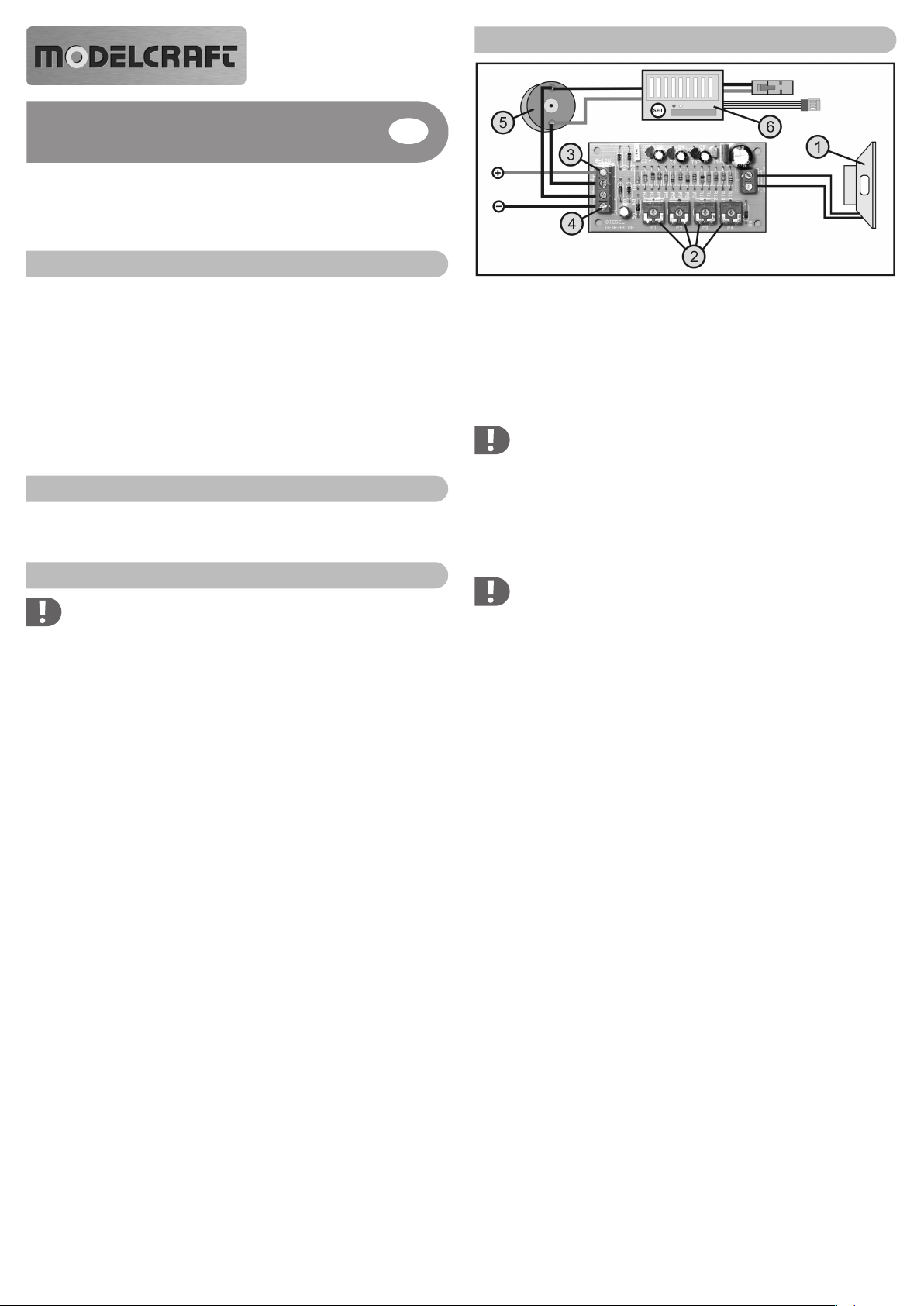
Figure 1
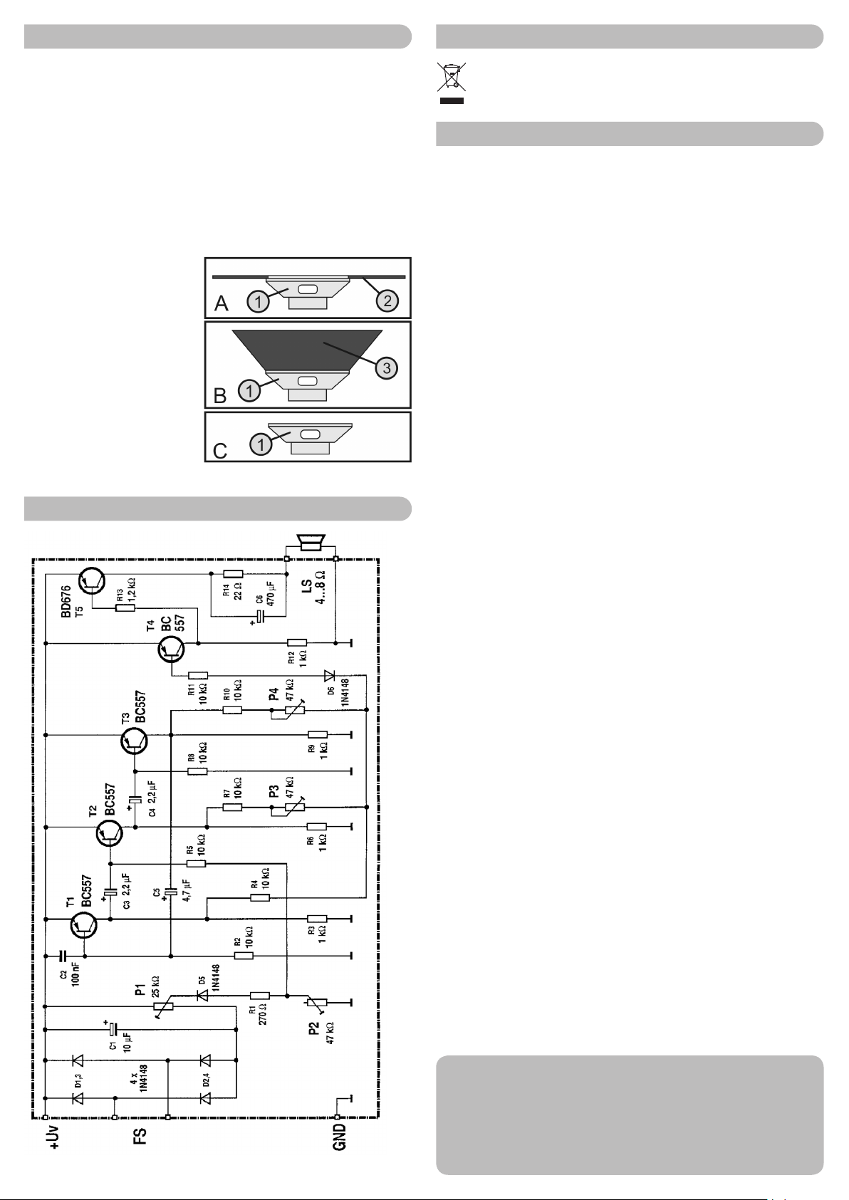
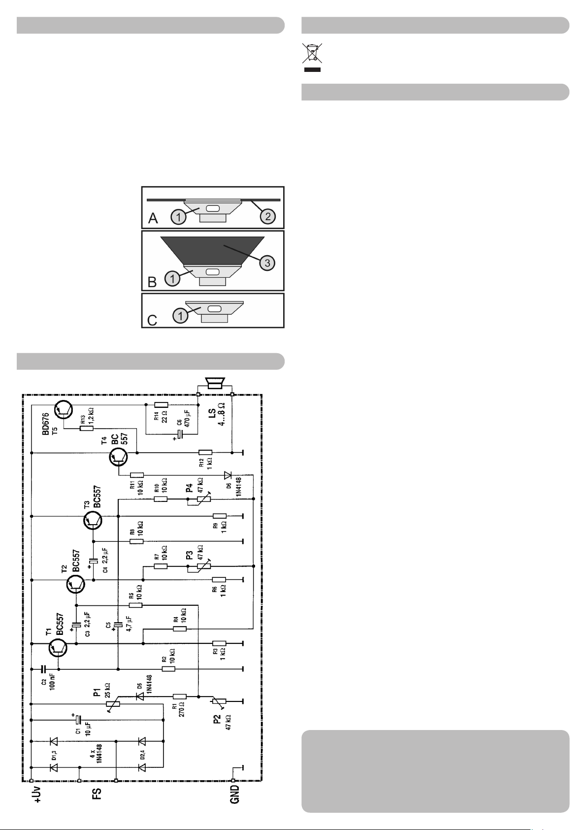
• Connectez un haut-parleur miniature sur la borne à deux broches « LS » (voir gure 1,
Pos. 1). Le haut-parleur doit présenter une impédance de 4 - 8 ohms.
• En utilisant un tournevis approprié, positionnez les boutons de réglage P1 - P4 (voir gure 1,
Pos. 2) en position médiane. Pour ce faire, utilisez un tournevis de réglage en plastique pour
éviter tout court-circuit.
• Connectez la tension d‘alimentation (6 - 12 V/CC) aux bornes « + » (voir gure 1, Pos. 3) et
« - » (voir gure 1, Pos. 4) en respectant la polarité.
Important !
Respectez impérativement la bonne polarité, sinon les composants de la carte seront
irréversiblement endommagés.
• En cas de branchement correct, après raccordement à la tension de service, un bruit de
moteur diesel doit être audible via le haut-parleur raccordé, qui peut être modié avec les
boutons de réglage P3 et P4.
• Si le bruit électronique doit dépendre de la vitesse de déplacement, les deux bornes « FS »
doivent être connectées parallèlement au moteur d‘entraînement (voir gure 1, pos. 5) Il n‘est
pas nécessaire de faire attention à la polarité des câbles de raccordement du moteur.
Remarque importante :
Le raccordement d‘un moteur de traction n‘est possible que s‘il y a dans le moteur
un moteur à courant continu (moteur collecteur avec deux câbles de raccordement)
avec régulateur de vitesse approprié (voir gure 1, pos. 6).
Un moteur sans balai (avec 3 câbles de raccordement) ne peut pas être raccordé à
un générateur de bruit de moteur diesel.
• Réglez le moteur de traction du modèle sur la vitesse de rotation maximale en utilisant la
commande à distance. À l‘aide du bouton de réglage P1, le bruit de moteur diesel est main-
tenant réglé sur la vitesse de rotation maximale.
• Éteignez ensuite le moteur de traction du modèle avec la télécommande. À l‘aide du bouton
de réglage P2, le bruit de moteur diesel peut maintenant être réglé pour le son à l‘arrêt.
• Le bruit de moteur diesel émis par le haut-parleur varie maintenant en fonction de la vitesse
de déplacement.
• Si le bruit de moteur diesel est indépendant de la vitesse de déplacement, les bornes
« FS » ne sont pas alors connectées et le bruit de moteur souhaité est réglé avec le bouton
de réglage P2.
#
7

Intégration dans le modèle
• Placez le générateur de bruit de moteur diesel dans un boîtier en plastique approprié ou dans
un emplacement protégé de votre modèle. Fixez-le avec du ruban adhésif double-face.
• Veillez à ce que la ventilation de la carte soit sufsante. Il faut également faire attention à ce
qu‘aucune pièce métallique n‘entre en contact avec les composants ou les lignes de circuit
de la carte. Vous courez alors un risque de court-circuit !
• Placez les câbles de raccordement de sorte qu‘ils en puissent pas se détacher à cause des
vibrations. Utilisez les supports de câble appropriés.
• Le bruit du moteur diesel est très dépendant du haut-parleur utilisé et de son installation.
Pour cette raison, nous vous recommandons de fournir au haut-parleur (voir croquis A - C,
Pos. 1) un déecteur en carton (voir croquis A, Pos. 2) ou un pavillon (voir croquis B, Pos. 3).
Évitez d‘utiliser le haut-parleur sans bafe dans un court-circuit acoustique (voir croquis C).
Figure 2
Diagramme du circuit
Élimination
Les produits électriques/électroniques ne doivent pas être jetés dans les poubelles
ordinaires. Il convient de procéder à l‘élimination du produit au terme de sa durée de
vie conformément aux prescriptions légales en vigueur.
Caractéristiques techniques
Tension de fonctionnement...................6 - 12 V/CC
Puissance absorbée.............................max. 200 mA
Fréquence de sortie..............................env. 160 - 400 Hz, réglable avec un potentiomètre rota-
tif
Impédance du haut-parleur ..................4 - 8 ohms
Dimensions (h x l x p)...........................80 x 40 x 22 mm
Ce mode d‘emploi est une publication de la société Conrad Electronic SE, Klaus-Conrad-Str. 1,
D-92240 Hirschau (www.conrad.com).
Tous droits réservés, y compris de traduction. Toute reproduction, quelle qu‘elle soit (p. ex. photocopie,
microlm, saisie dans des installations de traitement de données) nécessite une autorisation écrite de
l‘éditeur. Il est interdit de le réimprimer, même par extraits.
Ce mode d‘emploi correspond au niveau technique du moment de la mise sous presse. Sous réserve
de modications techniques et de l‘équipement.
© Copyright 2013 by Conrad Electronic SE.

Gebruiksaanwijzing
Versie 06/13
Dieselmotorgeluidsmodule-component
Bestelnr. 22 52 23
Beoogd gebruik
Het product is bestemd om dieselmotorgeluiden te produceren in daarvoor geschikte model-
len (vissersboten of trucks). Het elektronische motorgeluid kan met vier instelknoppen indi-
vidueel worden ingesteld. Bovendien kan met behulp van de spanning van de aandrijfmotor
(collectormotor) het dieselmotorgeluid automatisch aan de rijsnelheid van het model worden
aangepast.
Voor de werking is nog een geschikte luidspreker met een impedantie van 4 – 8 Ohm vereist
(niet bij de levering inbegrepen, apart te bestellen).
Dit product voldoet aan de wettelijke, nationale en Europese eisen. Alle hierin voorkomende
rma- en productnamen zijn handelsnamen van de betreffende eigenaar. Alle rechten voor-
behouden.
Omvang van de levering
• Geluidgenerator
• Bedieningshandleiding
Veiligheidsaanwijzingen
Bij schade, die voortkomt uit het niet opvolgen van deze bedieningshandlei-
ding, vervalt de waarborg/garantie. Wij zijn niet verantwoordelijk voor gevolg-
schade! Bij materiële schade of persoonlijk letsel, veroorzaakt door onvakkun-
dig gebruik of het niet opvolgen van de veiligheidsaanwijzingen kunnen wij
niet verantwoordelijk worden gesteld. In dergelijke gevallen vervalt de waar-
borg/garantie!
a) Algemeen
• Uit veiligheids- en toelatingsoverwegingen (CE) is het zelfstandig ombouwen en/of wijzigen
van het product niet toegestaan.
• Het product is geen speelgoed, houd het uit de buurt van kinderen.
• Het product mag niet vochtig of nat worden. Bescherm het tegen hitte, kou, zonlicht, trillin-
gen, stof en vuil.
• Het product mag niet in explosieve gebieden worden gebruikt.
• Laat verpakkingsmateriaal niet achteloos rondslingeren, dit kan voor kinderen gevaarlijk
speelgoed zijn.
• Ga voorzichtig met het product om, door stoten, slagen of vallen –zelfs vanaf geringe hoogte-
raakt het beschadigd.
b) Aansluiting
• De aansluiting mag uitsluitend in spannings-/stroomloze toestand plaatsvinden.
• Voor de aansluiting van het bouwpakket is een geschikte schroevendraaier nodig.
• Let bij de aansluiting van de voedingsspanning op de juiste polariteit van de aansluitkabels.
Een onvakkundige aansluiting kan leiden tot beschadiging van het product en tot verlies van
de waarborg/garantie! Laat de aansluiting in geval van twijfel door iemand anders uitvoeren,
die over voldoende vakkennis beschikt.
• Het product mag uitsluitend vast worden gemonteerd, bijv. in een daarvoor geschikte behui-
zing worden gebruikt. Gebeurt dit niet, dan kan kortsluiting optreden waardoor de bouwsteen
onherstelbaar wordt beschadigd. Verlies van waarborg/garantie!
• Neem de informatie in de paragraaf „Technische gegevens“ in acht.
Het product mag uitsluitend via een gestabiliseerde gelijkspanning van 6 - 12 V/DC worden
gebruikt; de benodigde luidspreker moet over een impedantie van 4 - 8 Ohm beschikken.
Aansluiting en ingebruikname
Afb. 1
• Sluit op de 2-polige klem „LS“ een miniluidspreker aan (zie afb. 1, pos. 1). De luidspreker
moet over een impedantie van 4 - 8 Ohm beschikken.
• Zet met een geschikte schroevendraaier de sleper van de instelknop P1 - P4 (zie afb. 1,
pos. 2) in de middelste stand. Gebruik daarvoor een kunststof-instelschroevendraaier, om
kortsluitingen te vermijden.
• Sluit op de klemmen „+“ (zie afb. 1, pos. 3) en „-“ (zie afb. 1, pos. 4) de voedingsspanning
(6 - 12 V/DC) met de juiste polariteit aan.
Belangrijk!
Let te allen tijde op de juiste polariteit, omdat anders de componenten van de print-
plaat onherstelbaar beschadigd raken.
• Bij de juiste aansluiting moet na aansluiting van de bedrijfsspanning al een dieselmotorgeluid
uit de aangesloten luidspreker te horen zijn, dat met de instelknoppen P3 en P4 kan worden
aangepast.
• Als het elektronische rijgeluid afhankelijk moet zijn van de snelheid, moeten de beide klem-
men „FS“ parallel op de rijmotor (zie afb. 1, pos. 5) worden aangesloten. Er hoeft daarbij niet
op de polariteit van de aansluitkabels van de motor te worden gelet.
Houd er rekening mee:
De aansluiting van een rijmotor is alleen dan mogelijk, als het bij de motor een gelijk-
stroommotor (collectormotor met 2 aansluitkabels) met overeenkomstige rijregelaar
(zie afb. 1, pos. 6) betreft.
Een brushlessmotor (met 3 aansluitkabels) kan niet op de dieselmotorgeluid-genera-
tor worden aangesloten.
• Breng de rijmotor van het model met de afstandsbediening op het maximale toerental. Met
behulp van de instelknop P1 wordt nu het dieselmotorgeluid eveneens op het maximale
toerental ingesteld.
• Schakel vervolgens de rijmotor van het model met de afstandsbediening uit. Met behulp van
de instelknop P2 kan nu het dieselmotorgeluid op stationaire sound worden ingesteld.
• Afhankelijk van de rijsnelheid verandert nu ook het geproduceerde dieselmotorgeluid uit de
luidspreker.
• Mocht het dieselmotorgeluid onafhankelijk van de rijsnelheid zijn, dan worden de klemmen
„FS“ niet bedraad en de gewenste motorsound met de instelknop P2 ingesteld.
$
7

Inbouw in het model
• Plaats de dieselmotorgeluid-generator in een geschikte kunststofbehuizing of breng hem aan
op een beschermde plek van uw model. Maak hem daar vast met een strook dubbelzijdig
plakband.
• Zorg ervoor dat de printplaat voldoende wordt geventileerd. Er dient tevens op gelet te wor-
den, dat metalen delen niet in aanraking komen met de componenten van de printplaat resp.
met de geleidende banen. Kans op kortsluiting!
• Leg de aansluitkabels zodanig, dat ze door schokken of trillingen niet los kunnen raken.
Gebruik geschikte kabelzadels.
• De klank van het dieselmotorgeluid is zeer sterk afhankelijk van de gebruikte luidspreker en
de inbouw ervan.
Daarom adviseren wij u de luidspreker (zie schema A - C, pos. 1) van een geluidswand uit
karton (zie schema A, pos. 2) of een geluidstrechter (zie schets B, pos. 3) te voorzien. Ver-
mijd het, de luidspreker zonder geluidswand in de akoestische kortsluiting (zie schema C) te
gebruiken.
Afb. 2
Aansluitschema
Afvoer
Elektrische/elektronische producten horen niet in het huisvuil. Voer het product aan
het einde van zijn levensduur af conform de wettelijk geldende voorschriften.
Technische gegevens
Bedrijfsspanning...................................6 - 12 V/DC
Stroomverbruik .....................................max. 200 mA
Uitgangsfrequentie ...............................ca. 160 - 400 Hz, in te stellen via draaipotentiometer
Luidspreker impedantie ........................4 - 8 Ohm
Afmetingen (l x b x h)............................80 x 40 x 22 mm
Deze gebruiksaanwijzing is een publicatie van de rma Conrad Electronic SE, Klaus-Conrad-Str. 1,
D-92240 Hirschau (www.conrad.com).
Alle rechten, vertaling inbegrepen, voorbehouden. Reproducties van welke aard dan ook, bijvoorbeeld
fotokopie, microverlming of de registratie in elektronische gegevensverwerkingsapparatuur, vereisen
de schriftelijke toestemming van de uitgever. Nadruk, ook van uittreksels, verboden.
Deze gebruiksaanwijzing voldoet aan de technische stand bij het in druk bezorgen. Wijziging van tech-
niek en uitrusting voorbehouden.
© Copyright 2013 by Conrad Electronic SE.
Table of contents
Languages:
Other ModelCraft Motorized Toy Car manuals
Popular Motorized Toy Car manuals by other brands

LEGO
LEGO Red Beast RC 8378 Building instructions

Kyosho
Kyosho V-ONE R4 instruction manual

Realtree
Realtree Wonderlanes ATV Racer owner's manual

PACIFIC CYCLE
PACIFIC CYCLE RAM 3500 Firetruck owner's manual

Team Corally
Team Corally Python C-00181 Quick start user guide

Carrera RC
Carrera RC Nintendo Mario Kart Bumble V Assembly and operating instructions