Page 5 of 6
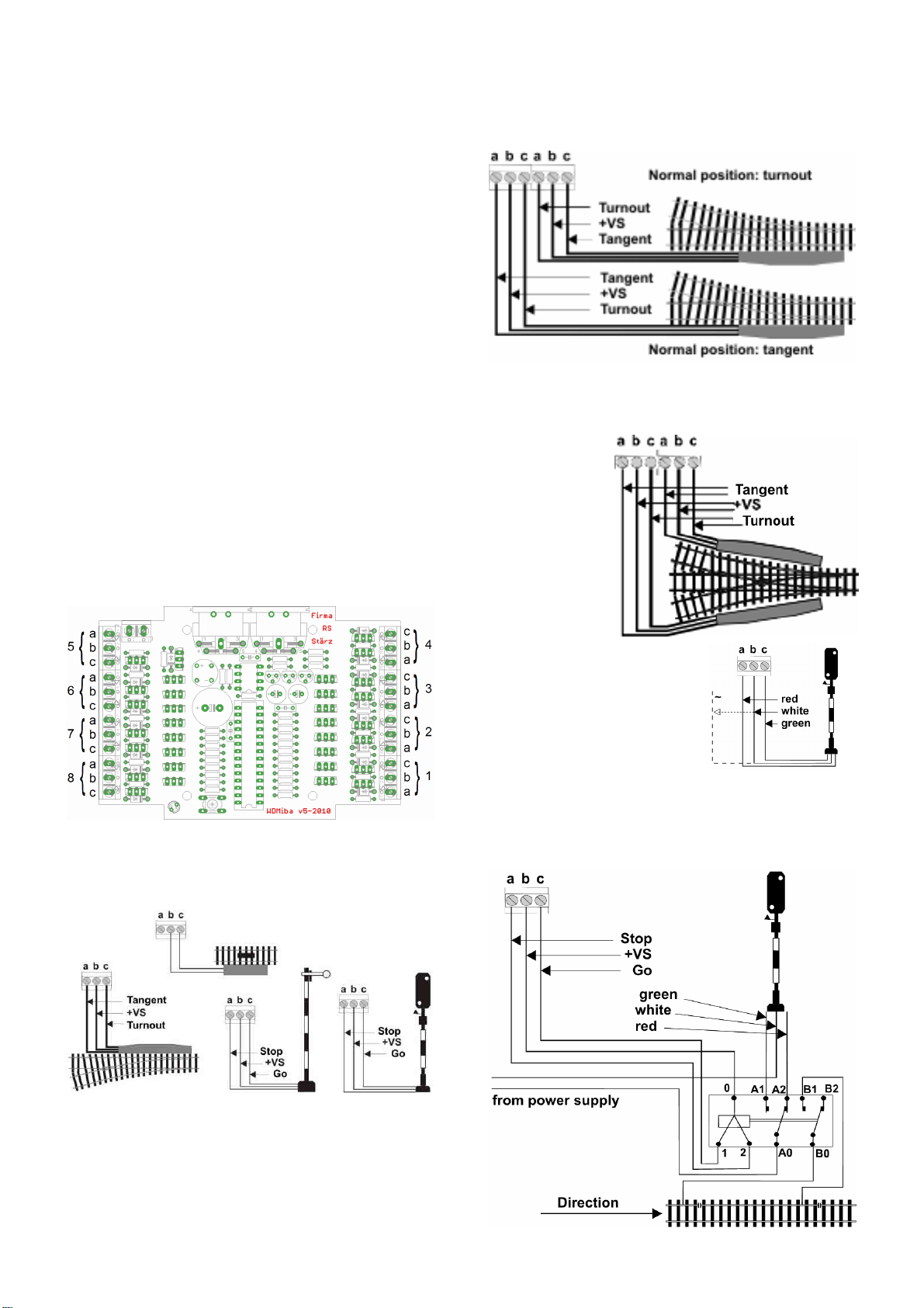
Connection of motorized turnouts
When connecting motorized turnouts, the
extension kit ESMot must be populated (for
the concerned outputs). Basically the connec-
tion of all motorized turnouts is the same: Both
contacts of the motor are directly connected to
the outputs of the Accessory Decoder
WDMiba, each at terminals a and c – terminal
b is left unconnected.
Some vendors of motorized turnouts equip their motors with an
additional circuitry (in most cases two diodes) which leads to more
than just two contacts. Usually there is one common ground (or
voltage supply) which is to be connected to terminal a. Additionally
there should be a contact for each turning direction which are to be
both connected to terminal c. There might be further wires but they
are not of interest for the connection to the Accessory Decoder
WDMiba.
Parameters and Programming
Programming
By programming the address of this module and all further pa-
rameters are set. In this section all parameters are explained.
Refer to the last page of these instructions for an example for the
programming procedure.
Convention Bit and Key
In information technology “Bit 0” to “Bit 7” is common.
For model railroaders a numbering of “bit 1” to “bit 8” is much more
convenient, as “Bit 1” becomes equal to “Key 1” or “position 1”.
This convention is used in these instructions.
Overview of parameters
Address 0: Address of this module 1 to 103 / 111 (80)
see table of addresses
Address 1: Timer assignment):
Bit value 0 (Off, “0” or “-“) assigns timer 1
Bit value 1 (On, “1” or “/”) assigns timer 2
Address 2: Timer 1 1 to 254, 255 (16)
Pulse length: 1 to 254: (80ms increments)
Continuous current: 255 (all bits 1)
Factory setting: 16 = pulse length 1.2 seconds.
Address 3: Timer 2 1 to 254, 255 (255)
Pulse length: 1 to 254: (80ms increments)
Continuous current: 255 (all bits 1)
Factory setting: 255 = continuous current
Address of this module
The address of this module can be set to any value in the range
from 1 to 111. Note that at certain central units addresses 104 to
111 are reserved for internal purposes during operation and should
thus not be used.
Also, addresses 0 to 3 are often used for programming parameters
of modules. Therefore these addresses should also not be used.
Operation mode
The Accessory Decoder WDMiba offers 2 operation modes:
Pulsed current and continuous current.
To allow controlling accessory types with different current require-
ments, for each of decoder’s eight output channels one of two
timers can be selected individually. Both timers (1 and 2) can have
either a pre-determined pulse length value or set to continuous
current.
Operation mode pulsed current
The operation mode pulsed current enables the output current only
for a specific time (set by the timer) after switching to this direction.
Afterwards, the output is off.
Not all solenoid powered accessories have the same requirements
for the duration of pulsed current to operate them. For instance, a
turnout with a double solenoid and limit stop can usually be oper-
ated with a 0.5 to 1 second pulse length. Theoretically it is possible
to operate this type of turnout with continuous current, but if the
limit stop is not working, the solenoid will get damaged. Solenoid
turnouts without limit stop should be controlled with pulses lasting
0.2 to 0.5 seconds.
On the other hand, there are slowly moving turnouts and sema-
phore signals. These might require pulse lengths of 4 to 8 sec-
onds.
Uncoupler tracks should as well not be operated with continuous
current. Instead, select a pulse with a length of up to 20 seconds
for uncouplers.
Operation mode continuous current
The operation mode continuous current enables the output current
permanently, so one of the dual-port outputs is always active.
For a light signal an output of continuous current is required which
lights up red on Stop but lights up green on Go instead. Only one
of the two lights is activated at the same time.
Timers 1 and 2
Both timers of the Accessory Decoder WDMiba are equal which
means that they can be programmed independently to any pulse
length between 0.08s (80ms) and 20 seconds with 80ms incre-
ments, by selecting values from 1 to 254. Both timers can also be
set to identical pulse lengths or continuous current mode (by pro-
gramming value 255).
For each of the 8 decoder output channels one of those 2 timers is
assigned.
Timer 1 is assigned for all output channels where operation mode
0 is selected; timer 2 is assigned for all output channels where
operation mode 1 is selected, respectively.
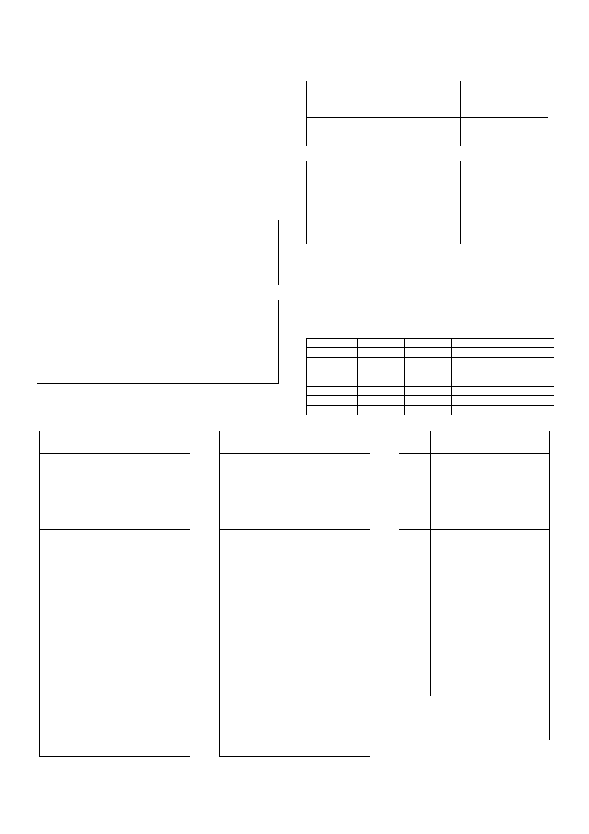
Overview of timers
The pulse length is calculated by summation of the separate bit
values (1 to 254) multiplied with the increment (0.08 s = 80 ms)
Bit 1 2 3 4 5 6 7 8
Value 1 2 4 8 16 32 64 128
Pulse 0,08 0,16 0,32 0,64 1,28 2,56 5,12 10,24
Value 255 (all bits ON) selects continuous current.
On the next page you’ll find a table with some examples.
Delayed output
In computer controlled and other automatic layouts several turn-
outs or signals are typically switched simultaneously. This could
result in excessive power consumption which exceeds the output
capacity of the decoder.
To prevent problems due to current peaks decoder outputs config-
ured for pulse type outputs are activated with 80 ms delay between
them when operated simultaneously. For channels set to continu-
ous current output, there is no delay between them in simultane-
ous operation.
Security monitoring system
Poorly laid wiring or malfunctions of system components may
result in a situation where a pulse type output is not switched off in
time. This can cause overheating or even burn a solenoid con-
nected to decoder output.
The Accessory Decoder WDMiba is equipped with a security
monitoring system (Watchdog) which cuts off the output current of
all output channels after about 2 seconds when an output pulse is
not terminated in time normally due to SX system malfunctions.
Factory default settings
Address of this module: 80
Operation mode: 0 0 0 0 0 0 0 0
(all output channels use timer 1)
Timer 1: 16 (1.28 seconds)
Timer 2: 255 (continuous current output)
If the address of this module is set to a value greater than 111, it
will be reset to the factory default setting (90).
Setting the address of this module to the value of 255 will reset all
parameters to their factory default settings.
Revert back to previous settings
Entering 0 as address, response or dropout delay reverts the
corresponding value to its previously programmed one.