3 Technical Data / Dati tecnici
3.1 General data / Caratteristiche generali
1Operating range
Range funzionamento 6-32 Vdc
2
Current output
Uscita in corrente
4..20 mA (2 wires)
4..20 mA (2 li)
3Functional insulation
Isolamento funzionale 1K Vac
4Output resolution
Risoluzione in uscita 2 μA
5Upper Linearity Limit
Limite linearità superiore f.s. + 5°C
6Lower Linearity Limit
Limite linearità inferiore f.s. - 5°C
7Failure output
Uscita guasto
selectable 21mA, 3,8mA or anyone
selezionabile tra 21mA, 3,8mA o nessuno
8Current output protection
Protezione uscita in corrente
30 mA approx.
30 mA circa
9Rejection / Reiezione 50-60 Hz
10 Max transmission error
Max errore di trasmissione 0,1% f.s.
11 EMI < 0,5%
12 Temperature coecient
Coeciente di temperatura < 100 ppm
13 Sampling time
Tempo di campionamento 300 ms
14 Response time (10..90%)
Tempo di risposta (10..90%) approx. 600 ms
15 Sealing / Grado di protezione IP 20
16 Conformity / Normative CE, EN 61000-6-4, EN 61000-6-2
3.2 Thermo-mechanic features / Caratteristiche
termomeccaniche
1Operating temperature
Temp. di funzionamento -40..+85 °C
2Humidity
Umidità
30-90% @ 40°C (non condensing / senza
condensa)
3Storage temperature
Temperatura di stoccaggio - 4 0. .+10 5° C
4Connections / Connessioni screw pins / morsetti a vite
5Conductors section
Sezione conduttori 1 mm2
6Wires strip
Spelatura conduttori 8 mm
7Enclosure / Custodia nylon (PA66)
8Dimensions / Dimensioni 23 mm, Ø 45 mm
4 Inputs / Ingressi
Current input
Ingresso corrente
Measuring range: 0..20 mA (default 4 - 20 mA)
Range di misura: 0..20 mA (default 4 - 20 mA)
Voltage input
Ingresso tensione
Measuring range: 0..10 V
Range di misura: 0..10 V
Resistance input
Ingresso resistenza
Measuring range: 0..4000 Ω
Range di misura: 0..4000 Ω
4.1 Connections / Connessioni
Resistance input
Ingresso resistenza
6..32Vdc
4..20mA
RUN
Current input
Ingresso corrente
6..32Vdc
4..20mA
RUN
6..32Vdc
4..20mA
RUN
6..32Vdc
4..20mA
+
RUN
Voltage input
Ingresso tensione
6..32Vdc
4..20mA
RUN
6..32Vdc
4..20mA
RUN
6..32Vdc
4..20mA
+
RUN
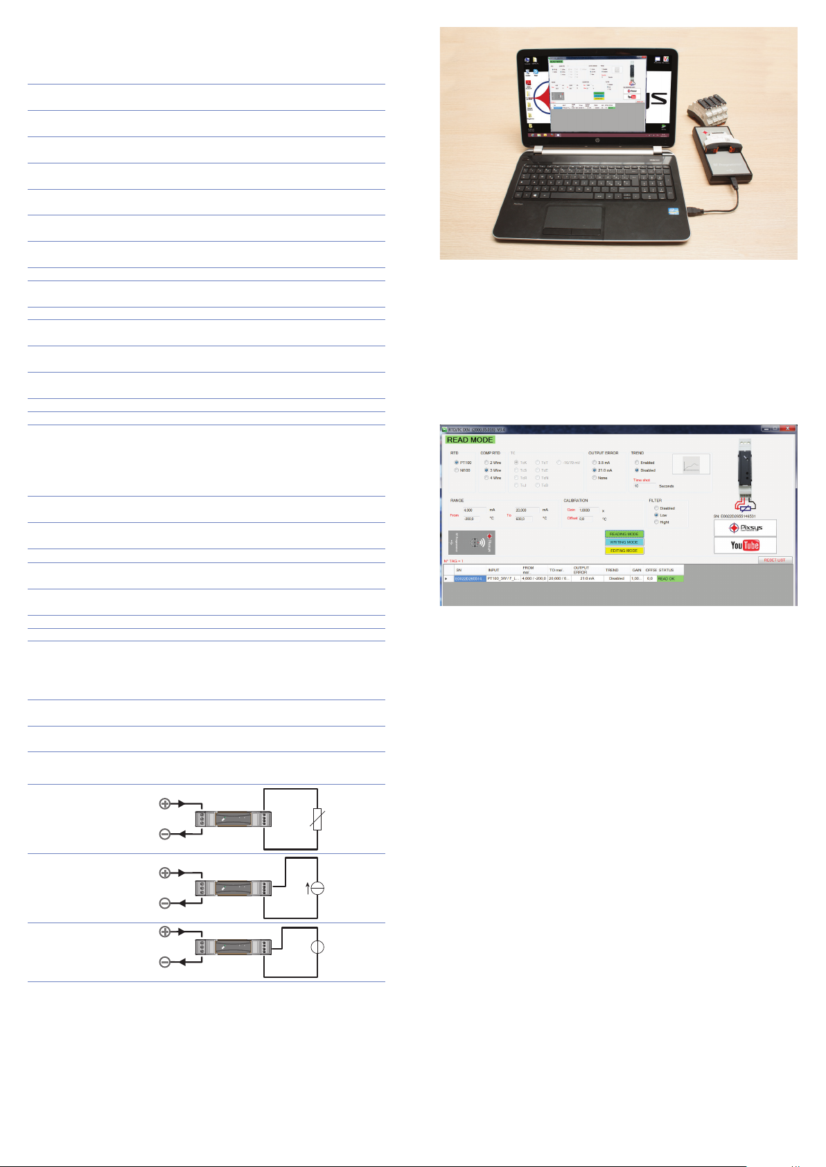
5 Conguration / Congurazione
To congure this signal converter it is necessary to use a RF Programmer and
the conguration software RF Programmer, available on download area www.
pixsys.net.
After connecting the RF Programmer via USB and activating the software is
possible, in “EDIT” mode, to congure the device input sensor, measuring range,
output current value and sampling frequency for the registration. The keys
“WRITE” and “READ” allow to write and read data on the devices quickly and
easily. On the lower side of the display a list of all programmed devices is showed; it
can be printed to conrm that the programming has been completed successfully.
La congurazione di questo convertitore di segnale richiede l’utilizzo di
un programmatore (RF Programmer) e del software di congurazione RF
Programmer scaricabile dall’area download nel sito www.pixsys.net.
Dopo aver connesso tramite porta USB l’RF Programmer e attivato il software
è possibile con la modalità “EDIT” parametrizzare il dispositivo selezionando il
tipo di sensore, range di misura, uscita per segnalazione errore e la frequenza
di campionamento per la registrazione. Con i tasti “WRITE” e “READ” è
possibile scrivere e leggere i vari dispositivi velocemente e in modo agevole.
Nella parte bassa dello schermo appare la lista riassuntiva dei dispositivi
programmati, che può essere stampata per certicare la buona riuscita delle
operazioni.
The input range can be set manually through the button placed under the frontal
closing cover. Press this button for 6s to access the conguration mode and set
the min. input value (slow ashing LED). Release the button to store the input
value which will be related to the min. output value (set on the corresponding
parameter, modication is possible only by a specic application, default 4mA).
Pressing the button for a further 6s it is possible to set the max. input value (fast
ashing LED). Release the button to store the input value which will be related
to the max. output value (set on the corresponding parameter, modication is
possible only by a specic application, default 4mA).
Input/output correspondence can be also set by a linearization table which is
editablethrougha specicsoftware orsmartphone application.Moreinstructions
are available on the software manual.
La pressione prolungata per 6 secondi permette di accedere alla modalità
di congurazione per impostare il valore minimo di ingresso (segnalata dal
lampeggio lento del led). Il rilascio del pulsante corrisponde al salvataggio
del valore letto in ingresso, che verrà associato al valore minimo di uscita
(valore impostato sul parametro corrispondente, la modica è possibile solo
da apposita applicazione, default 4mA). La pressione prolungata per ulteriori
6 secondi permette di impostare il valore massimo di ingresso (segnalata dal
lampeggio veloce del led). Il rilascio del pulsante corrisponde al salvataggio
del valore letto in ingresso, che verrà associato al valore massimo di uscita
(valore impostato sul parametro corrispondente, la modica è possibile solo
da apposita applicazione, default 20mA). La corrispondenza ingresso/uscita è
anche impostabile per mezzo di una tabella di linearizzazione la cui modica
è possibile tramite l’apposito software o app per smartphone. Ulteriori
istruzioni sono disponibili nel manuale del software.
6 Data Logger
This signal converter is provided with a datalogging function for the input signal.
Fixing the sampling time (1..3600 seconds) each time the loop 4..20mA powers the
device up, this will store the input value into a non-volatile memory. Through the
RF Programmer it is possible to download/display/print all data.
Questo convertitore di segnale è provvisto di una capacità di storicizzazione
del segnale in ingresso. Fissando il tempo di campionamento (impostabile
tra 1 e 3600 sec.) ogni volta che il loop 4..20mA alimenterà il dipositivo
questo archivia il valore in ingresso su una memoria non volatile. Tramite l’RF
Programmer è possibile scaricare tutti i dati e presentarli a video o stamparli.


