MODERN AG PRODUCTS CHOPPERRR User manual

C
h
oppe
rrr - 1
O
perator
’
s Manual
YOU'RE ALWAYS AHEAD...WITH A MODERN BEHIND.
CHOPPERRR
32%2;%($802177;
)$;
www.modernusa.com
Go Galvanized!
FALL 2011
SPRING 2017

2 CHOPPER
SAFETY SECTION
3CHOPPER
The SAFETY ALERT SYMBOL indicates
that there is a potential hazard to personal safe-
ty involved and extra safety precautions must be
taken. When you see this symbol on your ma-
FKLQH RU LQ WKLV PDQXDO EH DOHUW DQG FDUHIXOO\
read the message that follows it.
DANGER ,QGLFDWHV DQ LPPLQHQWO\ KD]DUGRXV
VLWXDWLRQ ZKLFK LI QRW DYRLGHG ZLOO UHVXOW LQ
death or serious injury. This signal word is lim-
ited to the most extreme situations.
WARNING ,QGLFDWHV D SRWHQWLDOO\ KD]DUGRXV
VLWXDWLRQ ZKLFK LI QRW DYRLGHG FRXOG UHVXOW LQ
death or serious injury.
CAUTION,QGLFDWHVDSRWHQWLDOO\KD]DUGRXVVLW-
XDWLRQZKLFKLIQRWDYRLGHGPD\UHVXOWLQPLQRU
or moderate injury. It may also be used to alert
against unsafe practices.
Driveline shields and gearbox shields should be
used and maintained in good working condi-
tion.
Do not mount or dismount the spreader while
the tractor id moving. Mount and dismount the
tractor only when it is completely stopped.
Do not turn sharp enough to get sever “knock-
ing” of the driveline which will cause accelerated
wear and breakage of drive train components
and possible injury from the separated driveline
sections.
Never allow riders on either tractor or spreader.
)DOOLQJFDQEHIDWDO
Never allow children to operate or ride on the
tractor or spreader.
Never work under the spreader unless it is
securely supported or blocked up. A sudden
or inadvertent fall by any of these components
could cause serious injury or death.
%HIRUH OHDYLQJ WKH WUDFWRU VHDW DOZD\V HQJDJH
the brake and or set the tractor transmission in
SDUNLQJJHDU'LVHQJDJHWKH372VWRSWKHHQ-
JLQH UHPRYH WKH NH\ DQG ZDLW IRU DOO PRYLQJ
parts to stop. Place the tractor shift lever into a
low range or parking gear to prevent the tractor
from rolling. Never mount or dismount a mov-
ing tractor. Operate the tractor controls from the
tractor seat only.
The rotating parts of this machine continue to
rotate even after the PTO has been turned off.
7KH RSHUDWRU VKRXOG UHPDLQ LQ KLV VHDW IRU
VHFRQGVDIWHUWKH EUDNHKDVEHHQVHW WKH372
GLVHQJDJHGWKHWUDFWRU WXUQHGRII DQG DOOHYL-
dence of rotation has ceased. “Wait a minute...
Save a life!”
5HPRYHK\GUDXOLFSUHVVXUHGLVHQJDJHWKH372
and turn off engine prior to doing any mainte-
nance.
Inspect the entire machine periodically. Look
IRUORRVHIDVWHQHUVZRUQRUEURNHQSDUWV0DNH
sure all pins have cotter pins and washers. Seri-
ous injury may occur from not maintaining this
machine in good working order.
!
OPERATION
WARNING
DANGER
DANGER
SAFETY SECTION

4 CHOPPER
Never operate the tractor and spreader until
you have read and completely understood this
PDQXDOWKHWUDFWRURSHUDWRU·VPDQXDODQGHDFK
of the Safety Messages found on the decals on
the tractor and spreader.
Always maintain the safety decals in good
readable condition. If the decal become dam-
DJHG RU XQUHDGDEOH RUGHU UHSODFHPHQW GHFDOV
immediately.
It may be necessary to shorten PTO shaft before
RSHUDWLRQWRSUHYHQWGDPDJHWRJHDUER[VKDIW
or operator.
PROLONGED EXPOSURE TO LOUD NOISE MAY
CAUSE PERMANENT HEARING LOSS.
Tractors with or without spreaders attached can
RIWHQ EH QRLV\ HQRXJK WR FDXVH SHUPDQHQW
partial hearing loss. We recommend that you
wear hearing protection on a full time basis if
WKHQRLVHLQWKHRSHUDWRU·VSRVLWLRQH[FHHGV
GE1RLVHRYHUGERQDORQJWHUPEDVLVFDQ
cause severe hearing loss. Noise over 90 db ad-
jacent to the operator over a long-term basis
PD\FDXVHSHUPDQHQWWRWDOKHDULQJORVV1RWH
hearing loss from loud noise is cumulative over
a lifetime without hope of natural recovery.
HYDRAULIC SYSTEM WARNINGS
ALWAYS release the pressure on the hydraulic
system of the CHOPPERRR prior to
removing the attachment from the skid steer
loader or working on any part of the
hydraulic system. Hydraulic hoses and compo-
nents operate under extreme pressure and
KHDW$VPDOOVWUHDPRIÁXLGIURPDSLQKROHOHDN
in a hydraulic hose can penetrate the
skin and/or cause burns. Whenever hydraulic
ÁXLGLVLQMHFWHGLQWRWKHERG\VHHN
medical attention at once to reduce chances of
a dangerous infection. ALWAYS wash
skin with soap and water after contact with hy-
GUDXOLFÁXLGDVLWLVDQLUULWDQWWRVNLQDQG
eyes.
CHOPPERRR rotary cutters have been designed
to reduce the likelihood of hydraulic
system leakage. Each and every hydraulic sys-
tem is checked prior to shipment.
+RZHYHU RYHU WLPHDQ\K\GUDXOLFV\VWHP PD\
GHYHORSÁXLGOHDNV9HU\VPDOOOHDNV
PD\SURGXFHKLJKSUHVVXUHGLVFKDUJHÁRZVFD-
pable of causing injury should skin come
in contact with such discharge.
/HDNLQJ ÁXLG FDQ PDNH WKH GHFN DQG JURXQG
VXUIDFHVYHU\VOLSSHU\FDXVLQJGLIÀFXOW\LQ
using tools and also increasing the possibility of
slips and falls. ALWAYS wipe away
DOO ÁXLG WKDW PD\ KDYH OHDNHG GXULQJ PDLQWH-
nance.
1(9(5RSHUDWHD&+233(555URWDU\FXWWHURQD
´KLJKÁRZµVNLGVWHHUORDGHUXQOHVV
WKHFXWWHULVHTXLSSHGZLWKD´KLJKÁRZµPRWRU
Motor failure can occur if such use is
performed. CHOPPERRR is NOT RESPONSIBLE
for damage incurred to the
K\GUDXOLFPRWRUGXHWR´KLJKÁRZµXVDJH3OHDVH
refer to the front cover of the manual
IRUWKHPD[LPXPDOORZDEOHÁRZIRU\RXU&+23-
PERRR rotary cutter.
WARNING
WARNING
WARNING
WARNING
CAUTION
SAFETY SECTION
5CHOPPER
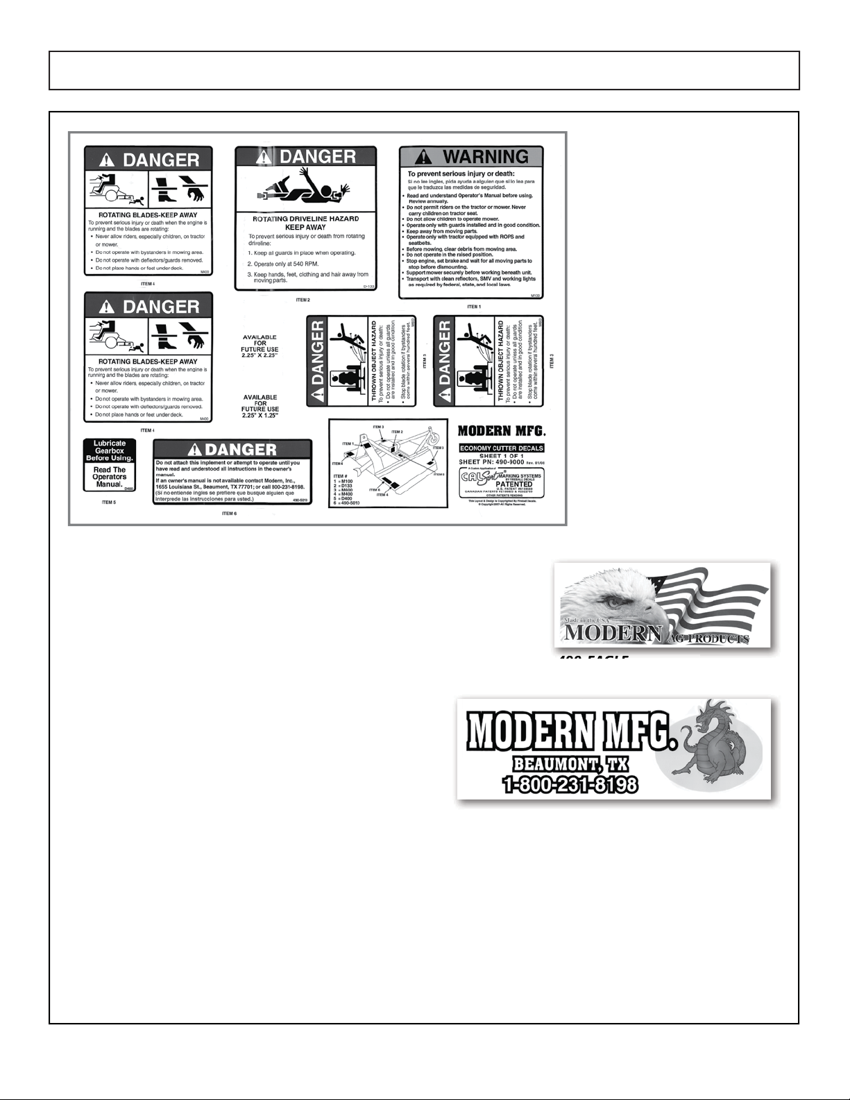
490-9000 Decal Sheet contains:
:DUQLQJ7R3UHYHQW,QMXU\
5RWDWLQJ%ODGHV.HHS$ZD\
(1) Rotating Driveline Hazard
'DQJHU5HDG2SHUDWRU0DQXDO
(1) Thrown Object Hazard
(1) Lubricate Gearbox
490-EAGLE
49
49
0
0
EA
EA
GL
GL
E
E
490-1031
SAFETY SECTION

6 CHOPPER
OPERATING INSTRUCTIONS

7CHOPPER
OPERATING INSTRUCTIONS
ATTACHMENT OF MACHINE
The installation of your CHOPPERRR rotary cut-
ter is the same for any other powered attach-
PHQWIRU\RXUVNLGVWHHUORDGHU
1. Pull up to the rotary cutter and connect it to
your skid steer loader.
6HFXUHWKHORFNGRZQOHYHURUOHYHUV
&RQQHFWWKHK\GUDXOLFKRVHVIURPWKHURWDU\
cutter to your machine. The hoses provided
DUH HTXLSSHG ZLWK TXLFNGLVFRQQHFW ÀWWLQJV
(both male and female) for ease of use.
CUTTING OPERATION
7KH&+233(555URWDU\FXWWHULVFDSDEOHRIDQG
LQIDFWLQWHQGHGWREHXWLOL]HGIRUPXOFKLQJWUHHV
and other vegetation of varying heights and
GLDPHWHUVRIXSWRµ²µ$VDVDIHW\IHDWXUH
ZKHQ FXWWLQJ ODUJH GLDPHWHU YHJHWDWLRQ WKH
CHOPPERRR rotary cutter is equipped with a hy-
draulic motor cushion valve for shut down of the
blade system. This feature lessens the chance of
GDPDJLQJWKHFXWWHU·VK\GUDXOLFV\VWHPRUEODGH
system when cutting larger diameter vegetation.
'LUHFWLRQVIRUXVHDUHDVIROORZV
CUTTING GROUND LEVEL
VEGETATION
Raise the rear of the CHOPPERRR rotary cut-
WHU DSSUR[LPDWHO\ µ ² µ DERYH JURXQG OHYHO
The deck of the rotary cutter should be sloping
downward and away from the operator. This is
the optimum position for cutting materials that
are close to the ground.
Please note: If the operator can see the blade
system in operation, the back of the rotary
cutter is raised TOO HIGH!
CUTTING ABOVE GROUND LEVEL
VEGETATION
Raise the front deck of the CHOPPERRR rotary
FXWWHU XS DSSUR[LPDWHO\ · ² · DERYH JURXQG
level. Do not lift the rear portion of the deck.
.HHSLWDSSUR[LPDWHO\µ²µDERYHJURXQGOHY-
el. Slowly drive into the vegetation and use the
hydraulic tilt (roll) the bend or push the vegeta-
tion over. As you bend the vegetation over and
GULYHLQWRLWWKHEODGHVZLOOFXWLWLQWR7KHYHJH-
tation can now be mulched by rotating the front
of the rotary cutter and driving forward several
feet. Then roll the back of the cutter down and
back-drag atop the vegetation.
OPERATING INSTRUCTIONS

8 CHOPPER
REPAIR AND MAINTENANCE
INSTRUCTIONS

9CHOPPER
PRE-MAINTENANCE & REPAIR STEPS
Prior to performing any repair or maintenance
ZRUNRQ\RXU&+233(555PDNHVXUHWKDWWKH
IROORZLQJVWHSVDUH$/:$<6IROORZHG
9LVXDOO\YHULI\WKDWWKHORFNGRZQSLQVDUHIXOO\
engaged through the quick attach.
5HOHDVH WKH SUHVVXUH RQ WKH URWDU\ FXWWHU·V
hydraulic hoses.
7XUQWKHVNLGVWHHUORDGHUHQJLQHRII
'LVFRQQHFWWKHK\GUDXOLFKRVHVWKDWFRQQHFW
to the skid steer loader.
BLADE REMOVAL
)ROORZ DOO VWHSV LQ WKH ´3UH0DLQWHQDQFH
Repair Steps” at the top of this page.
6/2:/< URWDWH WKH EODGH FDUULHU XQWLO WKH
blade-attaching nut is aligned in the access
hole.
)URP WKH WRS RI WKH GHFN LQVHUW D VRFNHW
through the access hole onto the blade nut.
Remove the nut and insure that the blade
drops to the ground. Repeat the process for
the remaining blades.
$IWHU WKH QXWV KDYH EHHQ UHPRYHG DQG WKH
EODGHV KDYH GURSSHG EDFN XS WKH VNLG
steer loader and CHOPPERRR to retrieve the
blades.
$IWHU UHWULHYLQJ WKH EODGHV ORZHU WKH
CHOPPERRR back to the ground and shut the
skid steer loader engine down.
,QVSHFW WKH EODGHV IRU GDPDJH DQG GHWHU-
mine if the blades need to be sharpened or
replaced.
Safety Note: When sharpening or replacing the cut-
ting blades, all blades must be either sharpened or
replaced to ensure proper blade balancing. NEVER
mix sharpened blades with new blades.
BLADE INSTALLATION
)ROORZ DOO VWHSV LQ WKH ´3UH0DLQWHQDQFH
5HSDLU6WHSVµDWWKHWRSRIWKLVSDJH
7LOWWKHIURQWRIWKH&+233(555XS
6HFXUHO\SRVLWLRQDµ[µSRVWRUHTXLYDOHQW
VWUHQJWKVWUXWXQGHUWKHIURQWRIWKH&+23-
PERRR and SLOWLY rotate the blade carrier
until the blade-attaching nut is aligned in the
DFFHVVKROH,QOLHXRIXVLQJDµ[µSRVWRU
RWKHU VWUXW WKH URWDU\ FXWWHU FDQ EH OHDQHG
against the trunk of a large tree and allowed
to stay in such position until the blade holder
LV UHPRYHG ,I WKH ODWWHU PHWKRG LV FKRVHQ
remember to scotch or chock the skid steer
ORDGHU·VWLUHVZLWKDEULFNORJRURWKHUDSSUR-
priate strength item.
,QVHUW WKH EROW XS WKURXJK WKH KROH LQ WKH
blade and the blade holder. Insert the lock-
washer and nut through the access hole and
hand-tighten.
8VH WKH VRFNHW WR ÀQLVK WLJKWHQLQJ WKH QXW
through the access hole that is located on top
of the deck. The nut should be tightened with
DWRUTXHZUHQFKWRIWOEV
&DUHIXOO\UHPRYHWKHµ[µRURWKHUVWUXWDQG
lower the CHOPPERRR to the ground.
!
!
REPAIR AND MAINTENANCE INSTRUCTIONS

10 CHOPPER
BLADE HOLDER REMOVAL
)ROORZ DOO VWHSV LQ WKH ´3UH0DLQWHQDQFH
5HSDLU6WHSVµsee page 5
7LOW WKH &+233(555 GHFN DW D QHDU YHUWLFDO
DQJOH &DUHIXOO\ DQG VHFXUHO\ SRVLWLRQ D µ [
µ SRVW RU HTXLYDOHQW VWUHQJWK VWUXW XQGHU
the rear portion of the CHOPPERRR deck. In
OLHXRIXVLQJDµ[µSRVWRURWKHUVWUXWWKH
IURQWSRUWLRQ RI WKH URWDU\ FXWWHU·VGHFN FDQ
be leaned against the trunk of a large tree
and allowed to stay in such position until the
blade holder is removed. If the latter method
LVFKRVHQ UHPHPEHUWRVFRWFKRUFKRFNWKH
VNLG VWHHU ORDGHU·V WLUHV ZLWK D EULFN ORJ RU
other appropriate strength item.
5HPRYH WKH FRWWHU SLQ DQG FDVWOH QXW WKDW
secures the blade holder to the gearbox. Be
FDUHIXOLQSHUIRUPLQJWKLVVWHSDVLWLVSRVVLEOH
that the blade holder will fall and cause bodily
damage.
5HVWDUW WKH VNLG VWHHU ORDGHU·V HQJLQH DQG
VORZO\EXWÀUPO\VWULNHLIUHTXLUHGWKHERWWRP
SRUWLRQ RI WKH URWDU\ FXWWHU·V GHFN RQ WKH
ground. Repeatedly strike the rotary cutter on
the ground until the blade holder falls off.
BLADE HOLDER INSTALLATION
)ROORZ DOO VWHSV LQ WKH ´3UH0DLQWHQDQFH
Repair Steps”. see page 5
5HSRVLWLRQWKH&+233(555LQDQHDUYHUWLFDO
position. Position the strut back under the rear
SRUWLRQRIWKHGHFNRUOHDQWKHIURQWSRUWLRQ
of the deck back against the tree.
&DUHIXOO\ SODFH WKH EODGH KROGHU EDFN LQWR
SRVLWLRQRQWKHVKDIWRIWKHJHDUER[PDNLQJ
sure that the splines in the shaft match up to the
grooves on the shaft. Be careful in performing
this step as it is possible that the blade holder
can fall and cause bodily damage.
6FUHZWKHFDVWOHQXWEDFNRQWRWKHVKDIWDQG
place the cotter pin back into the hole on the
shaft. Remember to bend at least one of the
prongs on the cotter pin.
HYDRAULIC HOSE REMOVAL
)ROORZ DOO VWHSV LQ WKH ´3UH0DLQWHQDQFH
Repair Steps”. see page 5
0DUN RU RWKHUZLVH GRFXPHQW WKH SURSHU
location of each hose. The hoses can be
LGHQWLÀHGE\HLWKHUKDYLQJDPDOHRUDIHPDOH
quick-disconnect coupling.
8VLQJ D FUHVFHQW ZUHQFK ORRVHQ WKH KRVH
connectors at the motor.
HYDRAULIC HOSE INSTALLATION
)ROORZ DOO VWHSV LQ WKH ´3UH0DLQWHQDQFH
Repair Steps”. see page 5
,GHQWLI\WKHSURSHUORFDWLRQIRUHDFKKRVHRQ
the hydraulic motor.
+DQGWLJKWHQ HDFK KRVH FRQQHFWRU 3HUIRUP
ÀQDOWLJKWHQLQJZLWKDFUHVFHQWZUHQFK
1RWH'2127XVH7HÁRQWDSHRUDQ\RWKHUWKUHDG
bonding material when installing the hoses into
the hydraulic motor.
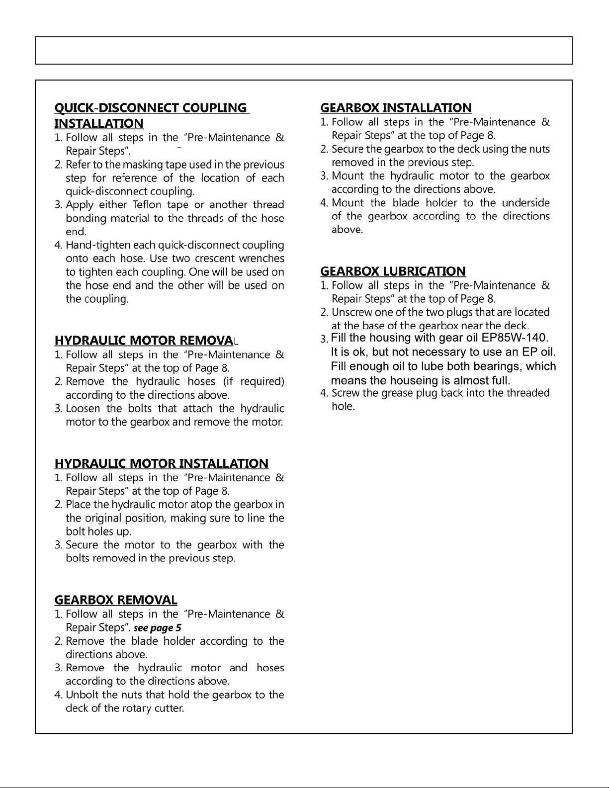
QUICK-DISCONNECT COUPLING
REMOVAL
)ROORZ DOO VWHSV LQ WKH ´3UH0DLQWHQDQFH
5HSDLU6WHSVµsee page 5
8VLQJ PDVNLQJ WDSH ODEHO HDFK KRVH ZLWK D
mark indicating which coupling was on it.
8VH WZR FUHVFHQW ZUHQFKHV WR UHPRYH WKH
quick-disconnect couplings. One will be used
on the hose end and the other will be used on
the coupling.
REPAIR AND MAINTENANCE INSTRUCTIONS
11CHOPPER
REPAIR AND MAINTENANCE INSTRUCTIONS
see page 9

12 CHOPPER
7
KL
VSDJH
L
QWHQW
L
RQD
OO
\
O
H
I
W
EO
DQ
N

13CHOPPER
ASSEMBLY/PARTS SECTION
ASSEMBLY/PARTS SECTION
14 CHOPPER
&GGFDUJWF'FCSVBSZ4LJE4UFFSDVUUFSTXJMMCFCVJMUVTJOH
5IJTDIBOHFXJMMGPMMPXBMMDVUUFSHPJOHGPXBSE
CFHJOOJOHXJUITFSJBMOVNCFS

15CHOPPER
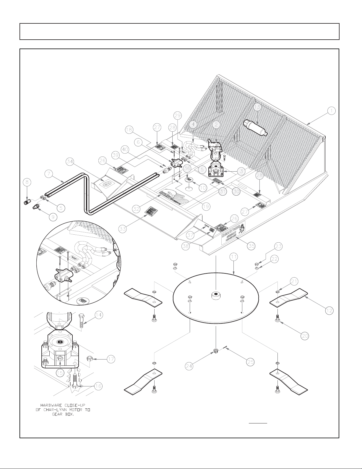
6’ Skid Steer Mower (Chopper) Parts List
Item Part Number Description Qty
1..............401-6SKIDSTEER .......6’ SKID STEER BODY ................................................1
2..............104-3654-006...........CHAR-LYNN MOTOR...............................................1
3..............401-0179..................GEAR BOX, MDH-40................................................1
4..............415-0160..................16” HOSE, 3/4” MPT X 7/8” ORB 14........................2
5..............50-118......................ST SWIVEL ADAPTER, 3/4MPT : 3/4FPT...................4
6..............262-1161..................CUSHION VALVE DRV-2HH.....................................1
7..............415-0096..................96” HOSE, 3/4MPT X 3/4MPT...................................2
8..............227-5053..................COUPLER, 1/2 FM PIPE 1/2-14NPSF........................1
9..............227-5054..................NIPPLE, 1/2 FM PIPE 1/2-14NPSF.............................1
10............116-1656..................MOWER DECK PLUG...............................................1
11............115-8019..................STUMP JUMPER, SKID STEER 41”..............................1
12............401-0156..................BLADE.......................................................................4
13............412-9099..................MANUAL HOLDER....................................................1
14............412-2007..................BOLT, 9/16”-12 X 2-1/2” GR8..................................2
15............412-2006..................TOP LOCK NUT, 9/16”-12........................................2
16............412-0023-02.............TAP BOLT, 5/8” X 2” GR5.........................................4
17............412-5284..................HEX NUT, 5/8-11 NC NYLOCK.................................4
18............400-0018..................BOLT, 5/16” X 3” UNC GR8.....................................2
19............620-5........................HEX NUT, 5/16” ........................................................2
20............125-907....................BLADE BOLT, 1-1/8” BB70........................................4
21............830-1018NH.............WASHER W/ KEYWAY..............................................4
22............900-8771..................LOCK WASHER, 1-1/8”............................................4
23............125-925....................JAM NUT, 1-1/8” GR8..............................................4
24............MDH40-120050........NUT, HEX SLOTTED, 1-14UNS ...................................1
25............501-0940..................COTTER PIN..............................................................1
*26..........M400........................DECAL, DANGER ROTATING BLADES....................2
*27..........M600........................DECAL, DANGER THROWN OBJECTS....................2
28............490-5010..................DECAL, DANGER DO NOT OPERATE.....................1
29............490-2003..................DECAL, MODERN ATTACHMENTS..........................1
30............490-FEMA.................DECAL, FEMA MEMBER...........................................1
31............490-1023..................DECAL, US FLAG......................................................1
32............490-EAGLE...............DECAL, EAGLE MADE IN AMERICA.......................1
*33..........M100........................DECAL, TO PREVENT SERIOUS INJURY ...................1
34............490-1105..................DECAL, “6”...............................................................1
*35..........490-1031..................DECAL, MODERN AG PRODUCTS .........................2
36............490-1024..................DECAL, CAUTION KEEP HANDS CLEAR.................1
*37............................................DECAL, MODERN MFG...........................................1
38............490-GALVCOAT......DECAL, CAUTION GALVANIZED COATING ..........2
(*) .......... 490-9000..................DECAL SHEET (CONTAINS ITEMS #26,#27,#33,#35 & #37)
ITEMS IN THIS SHEET ARE SOLD AS A SET ONLY. SEE PAGE 5.
ASSEMBLY/PARTS SECTION
3.................&KHFN9DOYH&9 ..........
.................+H[1LSSOH ..........
16 CHOPPER
ASSEMBLY/PARTS SECTION

17CHOPPER
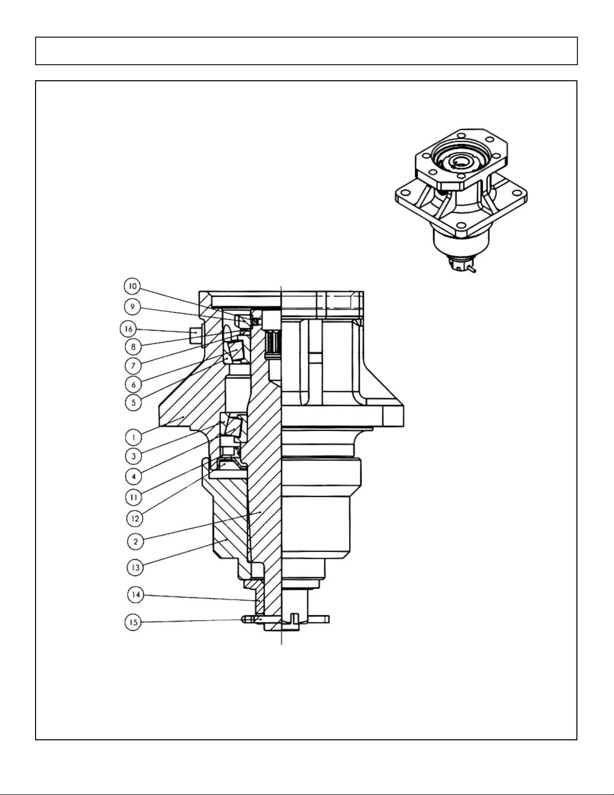
401-0179 Gearbox MDH-40 Parts List
Item Part Number Description Qty
1................................................HOUSING, MDH-40 .................................................1
2..............MDH40-040778........SHAFT-13Z INPUT SPLINE-11.....................................1
3..............MDH40-050200........BEARING, CUP 30210Y............................................1
4..............MDH40-050201........BEARING, CONE 30210X.........................................1
5..............MDH40-050239........BEARING, CUP 30209Y............................................1
6..............MDH40-050240........BEARING, CONE 30209X.........................................1
7..............MDH40-090464........WASHER WITH TANG...............................................1
8..............MDH40-130099........LOCK WASHER, M45...............................................1
9..............MDH40-120136........LOCKNUT, M45 X 1.5 BEARING ..............................1
10............MDH40-110304........SET SCREW, M5........................................................2
11............MDH40-060183........LIP SEAL-OUTPUT......................................................1
12............MDH40-240567........SEAL PROTECTOR....................................................1
13............MDH40-210034........BLADE HUB 15T ........................................................1
14............MDH40-120050........NUT, HEX SLOTTED, 1-14UNS ...................................1
15............MDH40-100001........COTTER PIN 5MM X 50MM......................................1
16............MDH40-140023........PLUG, PIPE SQUARE HEAD, 3/8”-18NPT.................2
ASSEMBLY/PARTS SECTION
(Reference only not included W/GB)
18 CHOPPER
ASSEMBLY/PARTS SECTION

19CHOPPER
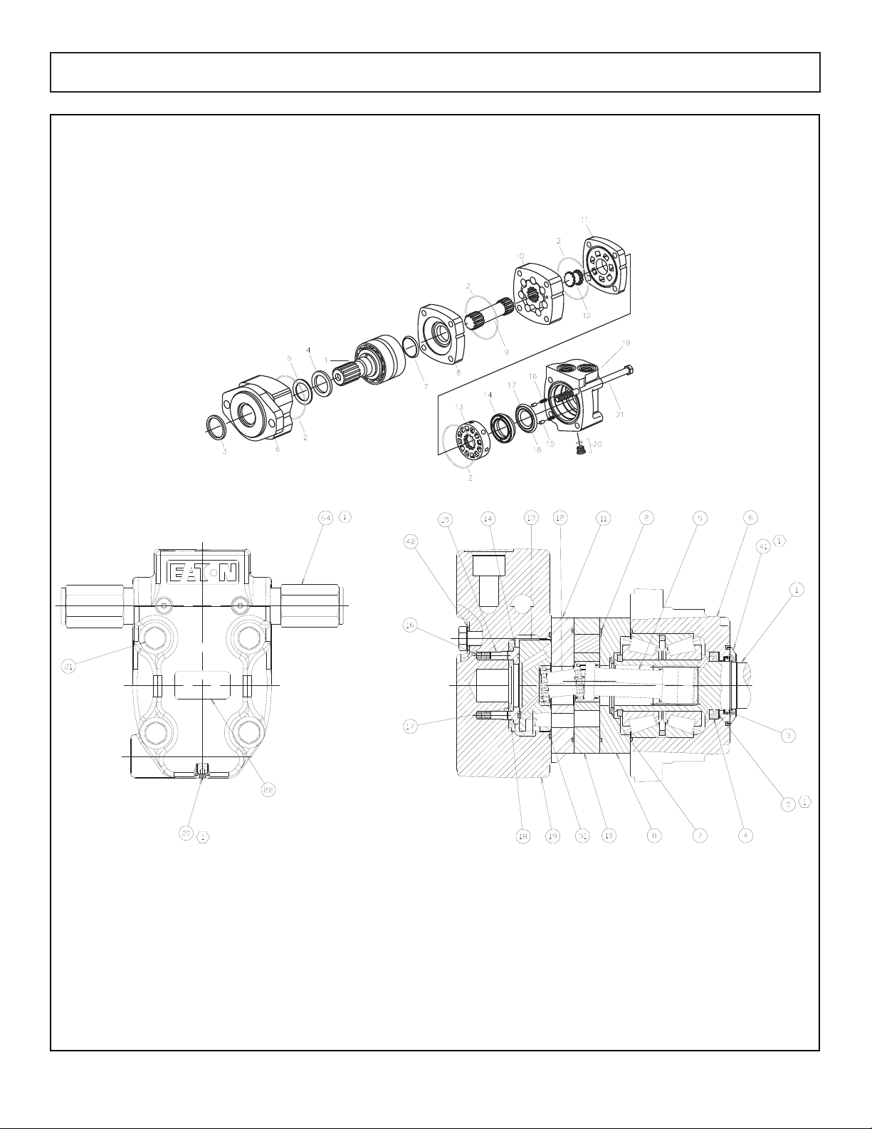
104-3654-006 Char-Lynn Motor Parts List
Item Part Number Description Qty
1..............21618-007................SHAFT SUB-ASSEMBLY .............................................1
2 .............4999136-001............SEAL..........................................................................4
3..............9121-001..................SEAL, SHAFT EXCLUSION.........................................1
4..............9057-009..................SEAL, SHAFT..............................................................1
5..............7382-000..................BACK-UP RING.........................................................1
6..............21578-001................HOUSING, BEARING................................................1
7..............9050-000..................SEAL, SHAFT FACE ...................................................1
8..............22102-000................PLATE, WEAR............................................................1
9 .............21371-010................DRIVE........................................................................1
10............21625-002................GEROLER SUB-ASSEMBLY........................................1
11............22134-000................PLATE, VALVE...........................................................1
12............8433-000..................DRIVE, VALVE ..........................................................1
13 ...........21466-000................VALVE.......................................................................1
14............8915-000..................PLATE, BALANCING.................................................1
15............14351-000................PIN ............................................................................2
16............7383-000..................SPRING.....................................................................2
17............9049-001..................SEAL, INNER FACE ...................................................1
18............9135-002..................SEAL, OUTER FACE ..................................................1
19............4994646-007............HOUSING, VALVE S/A.............................................1
20............9072-003..................PLUG SUB-ASSEMBLY...............................................1
21............14384-006................SCREW, CAP............................................................4
22............9029-007..................PLATE, NAME ...........................................................1
42............16048-184................WASHER ...................................................................4
51............250002-039..............SEAL..........................................................................1
64............02-199293................RELIEF VALVE S/A....................................................2
16096-610................PLUG, SHIPPING (NOT SHOWN).............................1
ASSEMBLY/PARTS SECTION

20 CHOPPER
LIMITED WARRANTY
POLICY & REGISTRATION
Table of contents
Other MODERN AG PRODUCTS Farm Equipment manuals


Popular Farm Equipment manuals by other brands

Schaffert
Schaffert Rebounder Mounting instructions

Stocks AG
Stocks AG Fan Jet Pro Plus 65 Original Operating Manual and parts list

Cumberland
Cumberland Integra Feed-Link Installation and operation manual

BROWN
BROWN BDHP-1250 Owner's/operator's manual

Molon
Molon BCS operating instructions

Vaderstad
Vaderstad Rapid Series instructions


