Modern Flames WMC-44LPM-ESP User manual

STUDIO SUITES
WALL MOUNT SUITE INSTALLATION
WMC-44LPM-ESP * WMC-44LPM-RTF* WMC-56LPM-ESP * WMC-56LPM-RTF * WMC-68LPM-ESP * WMC-68LPM-RTF * WMC-80LPM-ESP * WMC-80LPM-RTF
REVISED 07/17/2020

WHAT’S IN THE BOX? (WALL MOUNT SUITE)
•1x TOP & 1x BOTTOM CABINET
-WALL-MOUNT OPTION, TOP WILL HAVE A NOTCH ON RIGHT SIDE INSIDE FOR ELECTRICAL (FOR
READY TO FINISH MUST PAINT PRIOR TO INSTALL)
•2x MATCHING SIDE PIECES (FOR READY TO FINISH MUST PAINT PRIOR TO INSTALL)
•1x WALL MOUNT BRACKET
•4x CABINET INSTALL BRACKETS
•10x M3-.5 SCREWS FOR BRACKETS(2 are spares)
•8x #8 1-5/8” FOR SECURING TO STUDS
•8x #8 1” SCREWS FOR SECURING TO WALL ANCHORS
•8x WALL ANCHORS
•4x #8 ½” SELF DRILLING SCREWS FOR SECURING WALL MOUNT TO FIREBOX
•1x 120VAC 14AWG POWER CORD
•TOUCH UP PAINT * FOR ESPRESSO ONLY *
•***4 WIRE 240VAC CORD NOT INCLUDED***

WALL MOUNT BRACKET (x1)
CABINET MOUNT BRACKET (x4)
M3-0.5 X 12(X10)
(STYLE MAY VARY)
**HARDWARE FINISH MAY VARY
#8 X ½” SELF DRILLING(x4)
#8 X 1-5/8”(x8)
#8 X 1”(x8)
WALL
ANCHORS(x8)
MATCHING SIDE PIECES (x2)
TOUCH UP PAINT (x1)
(ESPRESSO ONLY)
120 VAC POWER CORD (x1)
TOP CABINET (x1)
BOTTOM CABINET (x1)

TOOLS NEEDED:
•TAPE MEASURE
•STUD FINDER
•LEVEL
•P2 PHILLIPS SCREW DRIVER
•PENCIL/MARKER
•DRILL WITH P2 PHILLIPS BIT
•DRYWALL SAW
•TOWELS
OPTIONAL:
-1/8” DRILL BIT FOR PILOT HOLES
-GLOVES
-VACCUUM
RECOMMENDED 2 PERSON INSTALLATION

OVERALL SUITE DIMENSIONS
ONCE INSTALLED
WALL MOUNT DIMENSIONS:
44 = 58.5”W x 28”H x 14.5”D
56 = 70.5”W x 28”H x 14.5”D
68 = 82.5”W x 28”H x 14.5”D
80 = 94.5”W x 28”H x 14.5”D
W
H
D

Select a suitable location for your fireplace suite. Consider the type of installation and the running of your electrical when choosing
the location. Electrical connects to the top right side of the fireplace. (see figure 1) Take into consideration your overall suite
dimensions when selecting an area. If you want to install your wall mounted electric fireplace suite into brick or masonry you’ll
need additional hardware beyond what is included in the standard installation kit provided with your suite; such as masonry
anchors & bolts. These are distinctly different from the wall anchors provided in the kit, used for drywall applications.
STEP 1
ALWAYS FOLLOW ALL
NATIONAL AND LOCAL CODES
ACCESS FOR RECESSED
ACCESS FOR WALL MOUNT
TERMINAL BLOCK
LOCATION
Provide a dedicated flexible 15 amp 120 volt circuit or
dedicated 4 wire 240 volt circuit for hard wire installation.
(FOR READY TO FINISH MUST PAINT PRIOR TO INSTALL)
Figure 1

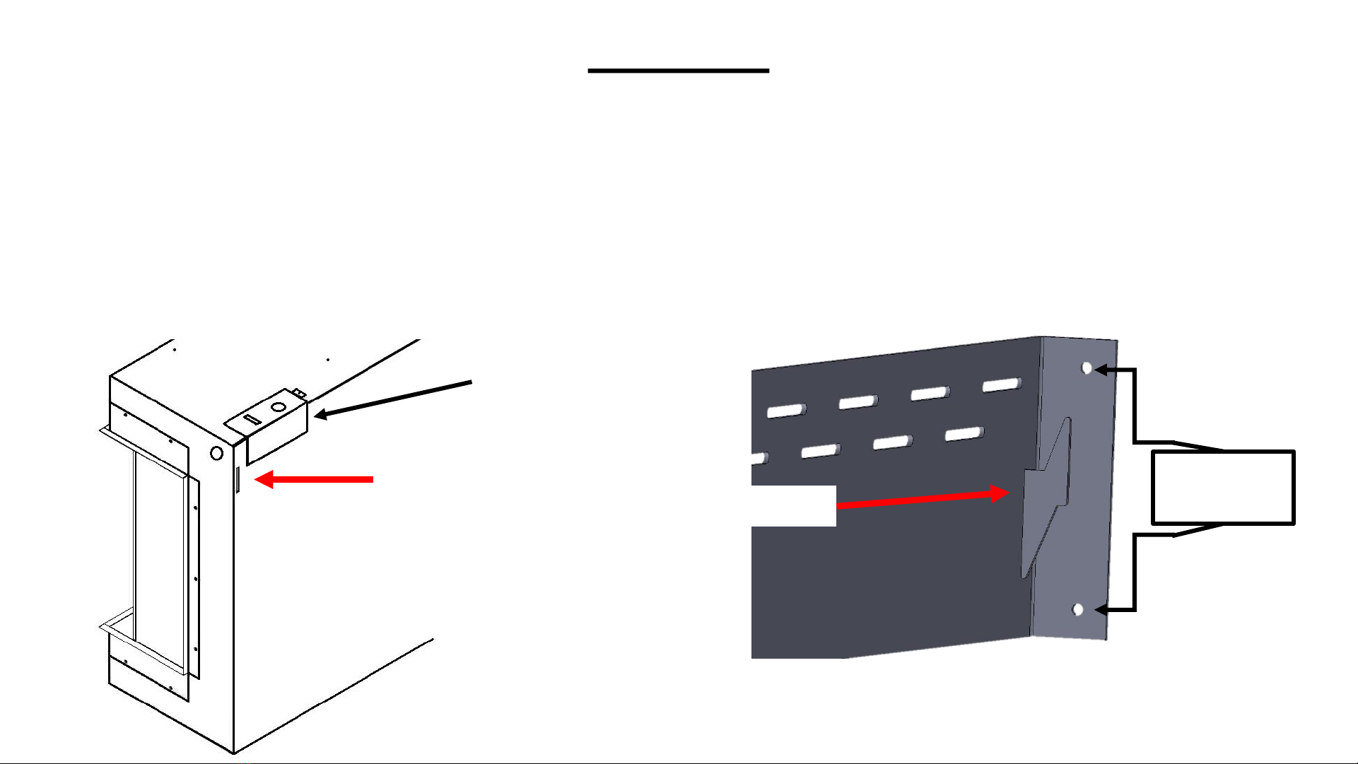
After you have selected a suitable location for wall mounting, locate the studs on the wall. You must be able to secure a
minimum of 2 studs for proper installation of bracket. (see figure 2) FAILURE TO DO SO CAN RESULT IN PERSONAL INJURY AND/OR
DAMAGE TO EQUIPMENT. Additional support is provided by using the included wall anchors between the studs.
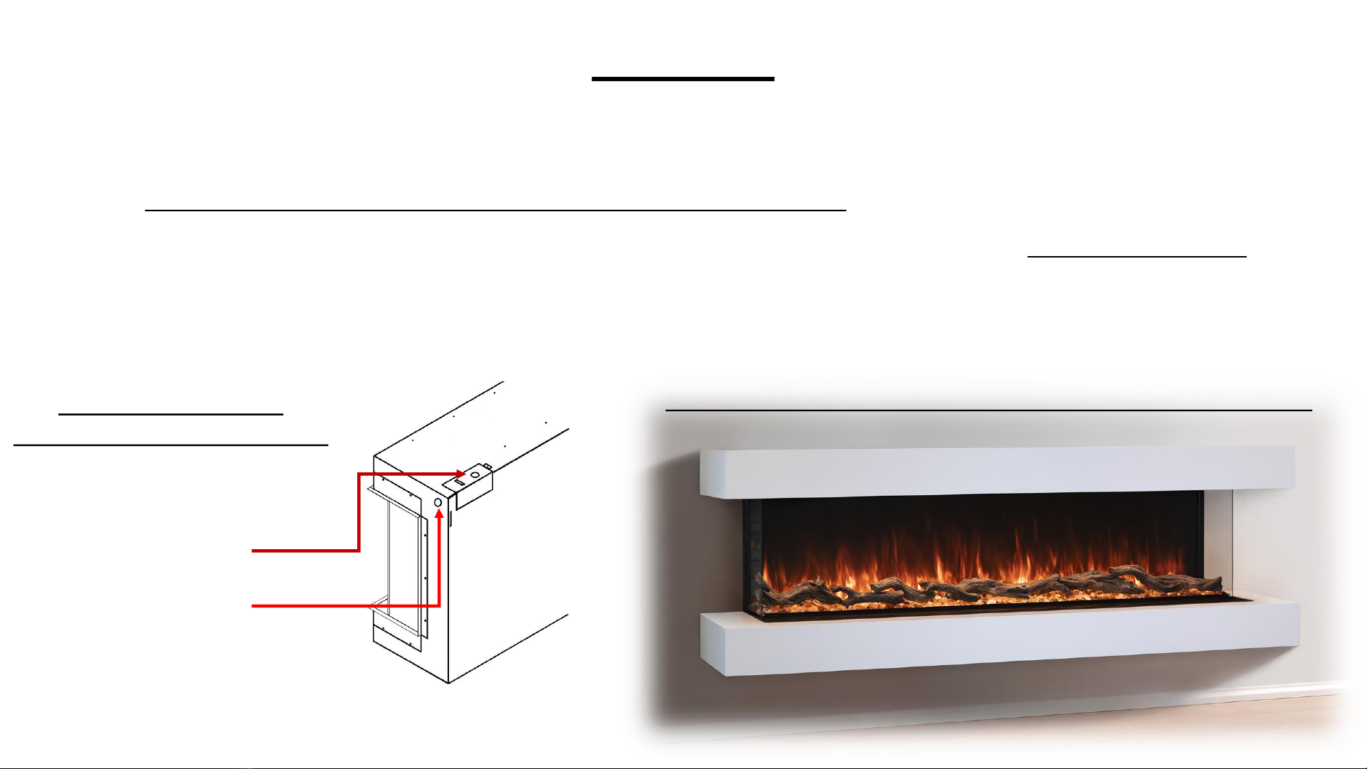
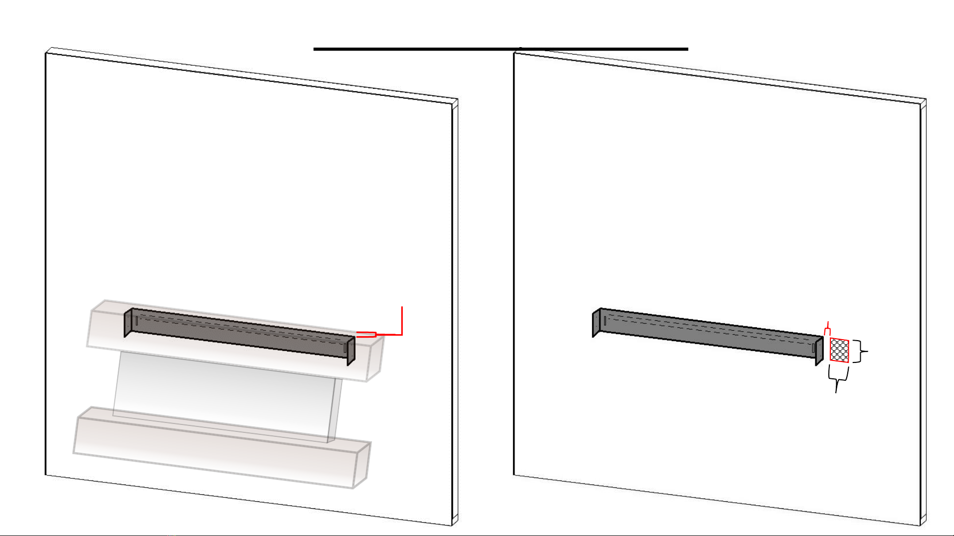
The top of the bracket will be the top of the fireplace which will be ¾” lower than the overall height with the cabinet installed.
(see figure 3) Measure where you would like the top of the fireplace to be and mark the wall. Hold the bracket to your desired
height, then align the bracket with studs and verify that the bracket is level. Once level, mark where you will secure the bracket
to the studs and mark where you will be installing the wall anchors.
*Note if using anchors those must be installed prior to securing bracket.
Mark the right side of the bracket so that a qualified electrician can either run a dedicated outlet per national & local codes.
See figure 4 on next page for example
STEP 2
EXAMPLE OF STUDS BEHIND WALL
SECURE THE BRACKET
TO THE STUDS
Figure 2

STEP 2 CONTINUED
2.25”
4.5”
4”
HARDWIRE OR OUTLET LOCATION
RIGHT SIDE OF BRACKET
2.25” AWAY FROM BRACKET
SPACE AVAILABLE 4”W x 4.5”H
0.75”(¾”)
TOP OF BRACKET IS 0.75” LOWER THAN
OVERALL HEIGHT.
Provide a dedicated 15 amp 120 volt circuit
or dedicated 4 wire 240 volt circuit for plug in
installation
Figure 3 Figure 4

•It is optional but with an 1/8” drill bit (NOT INCLUDED) pre-drill the holes for all of your marks
•Install wall anchors prior to installing bracket. It is recommended that wall anchors be installed with a Phillips tip screw driver. (figure7)
•Secure your bracket and align with marks (or pre-drilled holes) so that you can mount the bracket. (see figure 5)
•Verify the bracket is level and with #8- 1-5/8” screws secure bracket to wall studs. (see figure 6)
•Verify bracket is still level. If using anchors with the #8- 1” screws secure the bracket to the wall anchors.
(BRACKET MUST BE SECURED TO A MINIMUM OF 2 STUDS)
(MAKE SURE ALL SCREWS ARE FLAT ON THE BRACKET)
If installing into masonry perform same steps but follow masonry anchor manufacture instructions
STEP 3
FIGURE 7. EXAMPLE OF
ANCHOR INSTALL
Figure 5 Figure 6

•Locate the slots on the back of the fireplace (see figure 8), they are on the back top left and right of the fireplace.
This is where the hooks (see figure 9) on the bracket will hook into.
•Lift fireplace onto wall mount bracket and hook onto bracket.
•Locate the pilot holes on the side of the wall mount bracket. (see figure 9 & 10)
•With the(x4) #8-1/2” self-drilling screws secure the fireplace to the bracket. Pushing the fireplace towards the
bracket while securing will help ensure a snug installation.
•If hardwiring or plugging this may now be completed. (see figure 11)
STEP 4
SLOT
TERMINAL
BLOCK
LOCATION
HOOK
PILOT HOLE
LOCATION
Figure 8 Figure 9

STEP 4 CONTINUED
EXAMPLE OF SECURING FIREPLACE TO
WALL MOUNT BRACKET
CONNECT POWER CORD TO THE
FIREPLACE BY RUNNING THROUGH SIDE
ELECTRICAL ACCESS
REFERENCE MANUAL FOR CONNECTION
Figure 10 Figure 11

•Locate your cabinet mount brackets and M3-0.5 x 12 screws.
•These will be installed onto your fireplace drywall stops. (see figure 12 & 13) It is recommended you do one at a time. The
M3-0.5 screws will take place of the original screws securing the drywall stop. (see figure 14)
•Note orientation of cabinet mount bracket. Longer side must be away from the wall pointing towards you.
•The drywall stop and bracket will create a ¾” slot for the cabinets that make up the suite to slide onto. (see figure 15)
Diameter of hole in bracket is designed to give minor adjustment if needed.
•Complete install on all four corners of fireplace. (Top Left & Right, Bottom Left & Right)
STEP 5
CABINET MOUNT BRACKET
DRYWALL STOP
FRONT OF FIREPLACE
CABINET MOUNT BRACKET HOLES ALIGN ON DRYWALL STOP
Figure 12
Figure 13

STEP 5 CONTINUED
EXAMPLE OF INSTALLATION
BEST TO LEAVE HARDWARE LOOSE UNTIL BOTH SCREWS ARE STARTED FOR EASE OF INSTALLATION
¾” GAP
BRACKET STAND
OUT TOWARDS
FRONT
Figure 14
Figure 15

STEP 6
INSTALL SIDE GLASS FIRST INSTALL DESIRED MEDIA
INSTALL FRONT GLASS
Figure 16 Figure 17 Figure 18
1st
2nd
1st
2nd 1st
2nd
Reference fireplace install manual for additional information
GLACIER CRYSTALS
LOG SET

•Secure the bottom cabinet and align left and right onto brackets, see figure 19. Cabinet will slide in between the bracket
and drywall stops. MAKE SURE TO INSERT CABINET LEVEL & EVENLY TO AVOID DAMAGING CABINET. IF TOO TIGHT
REMOVE CABINET, LOOSEN BRACKETS, MAKE SPACING LARGER AND RE-TIGHTEN BRACKETS; THEN RETRY.
•Now locate your top cabinet. Remember it must have a notch on the inside to allow for power. Same steps performed as
the bottom cabinet install with the addition of making sure to hide any cables, see figure 20.
•See figure 21.1 & 21.2 for close up of cabinet sliding in between both brackets.
STEP 7
Figure 19 Figure 20

STEP 7 CONTINUED
CABINET SLIDING IN BETWEEN CABINET
MOUNT & DRYWALL STOP.
KEEP LEVEL AND MAKE SURE LEFT & RIGHT
GO IN EVENLY
Figure 21.1 Figure 21.2

STEP 8
START AT
DRYWALL STOP
THEN PUSH
BACK IN
REPEAT ON
OTHER SIDE
•Locate your two matching side pieces. Starting at drywall stop, slide the side piece in then push the remaining of side piece into place.
NOTE: These are friction fit. If there is not enough friction a construction adhesive or double sided tape may be used to help secure it.
SIDE PIECE
FIREPALACE
TOP CABINET
BOTTOM CABINET
FIGURE 22 FIGURE 23 FIGURE 24
This manual suits for next models
7
Table of contents
Other Modern Flames Electric Heater manuals