Modern Water OVA 5000 User manual

.
OVA 5000
ON-LINE HEAVY METALS ANALYSER
REFERENCE MANUAL
V1.3

Copyright © 2012 Modern Water Monitoring Ltd. All rights reserved.
Modern Water Monitoring Ltd.
15 –17 Cambridge Science Park
CAMBRIDGE CB4 0FQ
UNITED KINGDOM
Email: info@modernwater.co.uk
Web address: www.modernwater.com
Telephone: +44 (0) 1483 696000
P/N. 210-043-1.3

OVA 5000 Reference Manual V1.3 3
Contents
1Introduction 6
1.1 OVA 5000 Description.............................................................................................................................. 6
1.1.1 Electronic Compartment ................................................................................................................ 7
1.1.2 Wet Chemistry Compartment ........................................................................................................ 7
1.1.3 Reagent Compartment.................................................................................................................... 8
1.2 Typographical Conventions....................................................................................................................... 8
2Installation 9
2.1 Locating the OVA 5000 ............................................................................................................................ 9
2.2 Unpacking ................................................................................................................................................. 9
2.3 Power Connection ................................................................................................................................... 10
2.4 Reagent & Sample Connections.............................................................................................................. 10
2.5 Filter Unit Connections ........................................................................................................................... 10
2.5.1 Tubing Connections..................................................................................................................... 10
2.5.2 Catchpot Overflow Adjustment ................................................................................................... 11
2.5.3 Wiring Connections. .................................................................................................................... 11
2.6 Preparing For Operation.......................................................................................................................... 11
2.7 Adjusting Pump Tubing Tensioner ......................................................................................................... 13
2.8 Non Drain Pump Calibration................................................................................................................... 13
2.9 Drain pump calibration............................................................................................................................ 14
3OVA 5000 Software 15
3.1 Overview................................................................................................................................................. 15
3.2 Run Page ................................................................................................................................................. 16
3.2.1 Sweeps Tab.................................................................................................................................. 16
3.2.2 History Tab .................................................................................................................................. 16
3.2.3 Schedule Tab................................................................................................................................ 17
3.2.4 Manual Tab.................................................................................................................................. 17
3.2.5 Alarms Tab................................................................................................................................... 18
3.2.6 Status Tab..................................................................................................................................... 18
3.3 Manual Page............................................................................................................................................ 19
3.4 Configure System Page ........................................................................................................................... 19
3.4.1 Hardware Configuration Page...................................................................................................... 19
3.4.2 Metals Page.................................................................................................................................. 22
3.4.3 Scheduling Page........................................................................................................................... 22
3.4.4 Users & Passwords Page.............................................................................................................. 22
3.4.5 Technician’s Report ..................................................................................................................... 23
3.5 View Alarms Page................................................................................................................................... 23
3.6 Calibrate Pumps Page.............................................................................................................................. 23
4FieldPoint System 24
4.1 Overview................................................................................................................................................. 24
4.2 FieldPoint Explorer ................................................................................................................................. 24
4.3 FieldPoint in the OVA 5000.................................................................................................................... 24
4.3.1 Modules Used .............................................................................................................................. 24

OVA 5000 Reference Manual V1.3 4
5OVA 5000 Scripts 26
5.1 Sample Script .......................................................................................................................................... 26
5.2 Command List......................................................................................................................................... 26
5.2.1 System commands........................................................................................................................ 26
5.2.2 Analysis commands ..................................................................................................................... 26
5.2.3 Cell commands............................................................................................................................. 27
5.2.4 Pump commands.......................................................................................................................... 27
5.2.5 Probe commands.......................................................................................................................... 27
6Glossary Of Terms 28

OVA 5000 Reference Manual V1.3 5
Table of Figures
Figure 1. OVA 5000 Cabinet.................................................................................................................. 6
Figure 2. Filter stand assembly and connections .................................................................................. 11
Figure 3. OVA 5000 Main Screen........................................................................................................ 12
Figure 4. OVA 5000 Run Screen ......................................................................................................... 12
Figure 5. Peristaltic Pump .................................................................................................................... 13
Figure 6. Pump Calibration Screen....................................................................................................... 14
Figure 7. Main Screen .......................................................................................................................... 15
Figure 8. Run Screen............................................................................................................................ 16
Figure 9. Run Page History Tab........................................................................................................... 17
Figure 10. Configure System Page....................................................................................................... 19
Figure 11. Hardware Configuration Page............................................................................................. 20
Figure 12. Users & Passwords Page..................................................................................................... 23
Figure 13. FieldPoint Module Locations.............................................................................................. 25
Table of Tables
Table 1. OVA 5000 Power Requirements............................................................................................ 10
Table 2. FieldPoint Module Connections (for generic 6 pump OVA).................................................. 25

OVA 5000 Reference Manual V1.3 6
The On-Line Voltammetric Analyser (OVA) has been designed to enable reliable continuous on–line monitoring
of selected heavy metals. The robust and versatile OVA 5000 is suitable for use in a variety of industrial
applications.
Samples are taken automatically and analysed using the technique of Anodic Stripping Voltammetry. In some
instances the sample may require filtration, acidification or UV digestion before it can be analysed. All these
options are available and can be incorporated into the fully automated analysis cycle.
The manuals supplied with this instrument are:
Routine Service Manual. This is a very short manual for easy reference to only the weekly / fortnightly routine
maintenance and inspection procedures. It is designed for routine maintenance personnel who do not need
detailed understanding of instrument operation.
Operation Manual. This is a more detailed manual providing a general overview and more detailed information on
the generally important topics of instrument methodology and systems.
Reference Manual (this manual). Provides highly detailed information on instrument operation and configuration.
Much of this manual will not be of interest to the average user as the OVA 5000 is pre configured to user
specifications by Cogent Environmental technicians during installation.
Technical Service Manual. This manual provides technical details and drawings of OVA 5000 components. It will
mostly be of use as a reference document to service technicians.
1.1 OVA 5000 Description
The OVA 5000 On-Line Trace Metals Analyser has been designed for monitoring trace metals in aqueous
solutions using the electrochemical technique of Anodic Stripping Voltammetry. Examples of these metals are
Zn, Cd, Pb, Cu, Hg, & As.
Figure 1. OVA 5000 Cabinet
1Introduction

OVA 5000 Reference Manual V1.3 7
The instrument is controlled by an in built single board computer with an integral keypad and joystick mouse.
Voltammetry operations are controlled through a specially designed voltammetry card fitted inside the
electronics compartment behind the front panel. Pumps, as well as other hardware outputs, alarm outputs and
input channels are accessed via FieldPoint modules attached to the back wall of the electronic compartment.
The OVA program is used to operate the OVA 5000. The program functions are accessed using the keypad.
FieldPoint modules are used to control analytical sample and reagent handling, and data output.
The OVA 5000 is supplied with the appropriate software configured to run the application for which it was
originally specified. Other configurations can be supplied to change the application if required.
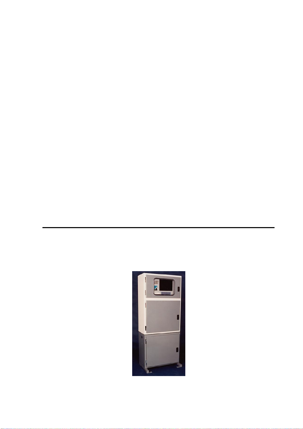
The OVA 5000 cabinet is divided into three compartments accessed by individual lockable doors.
1.1.1 Electronic Compartment
The upper compartment houses the main electronic components in a sealed compartment. The front panel
contains a 12.1" colour LCD with recessed keyboard mounted on a hinged frame for easy access to the inside of
the compartment. Attached to the inside of the back wall are the power supply modules and the rack of
FieldPoint modules.
1.1.2 Wet Chemistry Compartment
The middle compartment contains the analysis and sample treatment cells and the pumps used to add samples,
reagents and electrolytes and to carry out the cell rinses and cell drain.
Major components include:
Voltammetry Cell. The voltammetry cell has been carefully designed to ensure maximum response and
reproducibility. The working glassy carbon is situated on the floor of the cell, the Ag/AgCl reference
electrode is located in the side wall of the cell near the working electrode and the platinum counter electrode
enters at the back of the cell chamber.
The location of all three electrodes, including the counter electrode in the well at the bottom of the cell, is an
important feature of the OVA. A controlling voltage can be applied to the working electrode at all times
whilst the instrument is on, greatly improving analysis of "noble" metals such as gold, which are normally
deposited from solution onto carbon at low voltages. The technique of "medium exchange" is also
facilitated. In such cases, the electrolyte used for plating is exchanged for a different electrolyte for the
stripping analysis during the "hold" period.
The electro-analyte solution, is circulated in the cell by a specially designed stirrer, which to work
efficiently, must be covered with liquid and not have entrapped air bubbles in either the vertical or
horizontal orifices. Do not operate the stirrer at a speed greater than the recommended speed of 1500 rpm as
this will cause a vortex, allowing air to be trapped in the stirrer. The cell has a mechanically operated vent
for disposal of analyte after analysis.
Peristaltic Pumps. Up to thirteen peristaltic pumps can be operated sequentially to pump standards, samples,
electrolytes, plating and rinsing solutions.
External Reagent and Sample Line Connections. Situated in the base of the wet chemistry section are nine
ports which can be used for the inlet and outlet of solution lines, either directly or via bulk head connectors.
These include sample streams, electrolytes, standards, and plating and rinsing solutions. A dedicated drain
outlet for the voltammetric cell has been provided. Solution is drained from the cell and is removed to waste
through a length of tubing connected to a bulk head in the base of the wet chemistry section.
Spill Detector. The spill detector detects solution spillage below the voltammetric cell and pumps. Once
triggered the unit ceases operation and the fault alarm will be indicated.

OVA 5000 Reference Manual V1.3 8
1.1.3 Reagent Compartment
The lower compartment houses the reagent reservoirs. Enough containers can be placed here to provide
sufficient reagent for approximately 200 analyses (application dependant).
1.2 Typographical Conventions
The following kinds of formatting in the text identify special information.
Convention
Type of Information
Triangular Bullet()
Step-by-step procedures. You can follow these
instructions to complete a specific task.
Emphasis
Use to emphasize the importance of a point.
Special Bold
Items you must select, such as menu options,
command buttons.
Caution:
Important information.
Note:
A tip or an item of note.

OVA 5000 Reference Manual V1.3 9
2.1 Locating the OVA 5000
The OVA 5000 is sensitive enough to detect metal concentrations in solution down to parts per billion levels. As
an essential aspect of the design to achieve this level of sensitivity, the cell and electrical components of the
instrument are situated behind sealed lockable doors. To further ensure the reliability of the instrument there are
a number of basic requirements for the instrument and the convenience of the end user.
The instrument must be located in a sheltered area out of the elements so that it can remain as clean and dry as is
practical.
Distance from the sample source is recommended to be about 2 meters. In some cases, where the instrument
needs to be located some distance (>3m) from the sampling point, an auxiliary pump with or without a sampling
unit (filter) may be required, to deliver clean solution to the OVA sample intake tube.
A good power supply near to the instrument is an essential requirement. See section 2.3, Power Connection on
page 10.
This instrument is designed to run continuously and as such a good waste removal system should be put in place.
The OVA 5000 has been designed to be located on the reagent cabinet, which has mounting tabs on each of it’s
four legs. This enables the stand to be bolted to the floor holding the OVA 5000 firmly in place.
For the operator of the OVA 5000, clear access to the instrument and room to change chemicals and carry out
monthly maintenance should be allowed for.
2.2 Unpacking
Caution: Before turning on the OVA 5000, ensure all the instrument checks and procedures given in section 2.6,
Preparing For Operation on page 11 have been carried out.
Once the OVA 5000 is removed from its packaging and stood upright a visual inspection should take place by
the following procedure BEFORE TURNING ON THE INSTRUMENT:
External. Check that the cabinet and stand are not damaged or bent. Ensure the Perspex on the upper door is not
cracked and that both doors can be opened.
Internal. Open the upper door to obtain access to the OVA 5000 control compartment. Ensure the front panel is
not marked or bent in any way. Unscrew the two control panel holding studs on the right hand side and check
that the control panel freely opens and closes.
Remove the temporary packing which holds the reagent reservoirs in place.
Check that the wet chemistry component board and all attached is firmly in place and unmarked. Insert the
tubing into each peristaltic pump and close the clamp lid.
Check the Reference electrode, as described in section 4 of the Operation Manual, to ensure that an even brown
coating of AgCl covers the silver wire. If a new coating is required, follow the procedure given for replating in
section 4.5 of the Operation Manual using the Reference Plating Accessory.
2Installation

OVA 5000 Reference Manual V1.3 10
Check that the voltammetry cell is intact and the reference electrode chamber is filled with reference electrolyte
and there are no air bubbles. When required the working electrode should be inserted in the base of the cell with
the aid of the electrode key attached to the alligator clip lead. DO NOT TOUCH THE TOP OF THE
ELECTRODE.
Note: OVA 5000 inspection instructions are included in greater detail in the Routine Service Manual.
2.3 Power Connection
All external electrical connections enter the OVA 5000 via top right electrical connection glands. Access for
connection is obtained via the OVA 5000 control compartment front panel.
Mains Power: 220 - 240V or 110 -120V. Preset at factory.
Power Requirements
Typical
Maximum
OVA 5000
80 Watts
130 Watts
OVA 5000 with UV digester
101 Watts
151 Watts
Table 1. OVA 5000 Power Requirements
Caution: Earth must be connected to the instrument.
The input voltage to the OVA 5000 is connected, via the isolation switch, to fuse F1 and line filter LF1 on the
main terminal block TB1. The fuse F1 unit contains 3.15A HBC replaceable fuse. Terminal block TB2 has the
5V, 12V, ground and filter pump connections. Refer to Figure 13 on page 25 for these component locations.
2.4 Reagent & Sample Connections
The OVA 5000 has space for eight external reagent and sample connection ports in the base of the wet chemistry
compartment. These ports are provided to allow the flexibility of storing all reagents external to the unit if
required.
The instrument is supplied with “through” grommets for the connection of stream and reagent inlets suitable for
your application. A ¾ inch bulkhead fitting and various piping fixtures are provided for the drain outlet.
2.5 Filter Unit Connections
The OVA 5000 can be shipped with either a single or dual stream external filter unit, depending on the
application. Typically the filter unit should be mounted next to the OVA 5000 in order to reduce the purge time
of the sample line.
2.5.1 Tubing Connections
See Figure 2. Filter stand assembly and connections below.
Filter to Pump tube is supplied installed.
Pump to Catchpot tube is supplied installed. It should stop about 3 cm from the bottom to allow efficient
backflushing and ensure sufficient sample remains in the Catchpot for analysis after the backflush operation.
Catchpot to OVA tube (1.6mm Tygon supplied) connects the Barb connector at the bottom of the Catchpot
to the Raw Sample pump in the OVA.
Catchpot to Waste pipe (20mm PVC supplied) is the waste outflow from the centre of the Catchpot. It
should be connected to an appropriate waste stream or, if desired, back into the sample stream.
Sample source to Filter tube (1/4” poly supplied) connects the raw sample source to the bottom of the filter
(1/4” ID poly tubing supplied).

OVA 5000 Reference Manual V1.3 11
Figure 2. Filter stand assembly and connections
2.5.2 Catchpot Overflow Adjustment
Turn the black centre fitting on top of the catchpot to open the desired overflow hole in the centre of the
catchpot. Matching holes on the internal black piping should become visible for each overflow hole on the
outside white piping in turn as the fitting is turned. If holes aren’t easily visible it may be easier to manually fill
the catchpot to the top with water and turn the centre fitting until water is seen to drain through an open hole.
2.5.3 Wiring Connections.
Run the 2 wires coming out of the filter unit pump box through one of the grommets into the OVA electrical
compartment. Both wires are to be screwed into the top of the white terminal block, and matching the labels on
the 2 wires going into the bottom. One wire should be labeled “F” (fuse) and the other labeled “P” (pump). If
these wires are the wrong way around, then the filter pump will operate in reverse (when not backflushing).
2.6 Preparing For Operation
Once the OVA 5000 has been unpacked and checked, it must be tested to ensure correct operation.
Before switching the power on.
1Ensure the solution containers in the reagent cabinet are filled and the inlet pipe to the peristaltic
pumps is located in the bottle.
2Ensure that a working electrode is installed in the analyser cell.
3Ensure the working electrode alligator clip is disconnected.
4Ensure there is enough liquid in the cell to electrically connect all three electrodes. It may be necessary
to add liquid (preferably deionised water) manually with a syringe, pipette or wash bottle.
Caution. Always ensure that there is liquid covering the working electrode inside the voltammetry cell.
Failure to do this may cause an alarm condition.
Sample source to filter
Filter to Pump
Pump to Catchpot
Catchpot to OVA
Catchpot to Waste
Pump

OVA 5000 Reference Manual V1.3 12
Logging in to the OVA software.
1. Switch the instrument on with the red isolation switch located on the upper right hand side of the
cabinet. The OVA 5000 software should start automatically showing the Main screen shown below.
Figure 3. OVA 5000 Main Screen
2. Press the Log In button found in the bottom left of the screen and enter your username and password.
Click the Run button to enter the Run screen.
Figure 4. OVA 5000 Run Screen

OVA 5000 Reference Manual V1.3 13
2.7 Adjusting Pump Tubing Tensioner
Whenever the tubing is replaced in the peristaltic pumps, or the instrument has been unused for some time, it will
be necessary to adjust the tension screw on the tube clamp, shown in Figure 5.
Pump tubing tensioner adjustment procedure.
1. After releasing all tension on the tube clamp, select the Manual tab. Click the required pump to turn it on.
As the pump rotates, gradually increase the tube clamp tension by turning the tension screw.
2. Continue turning the tension screw until the pump begins to prime and pump solution through to the cell at
the optimum rate. Stop pump, and repeat on other pumps.
Note: Do not over-tighten the tension screw as this will stretch and kink the tubing and will reduce tube life.
TENSION
SCREW
TUBE CLIP
BARBED FITTING
TUBE
CLAMP
TUBE CLIP
BARBED FITTING
Figure 5. Peristaltic Pump
2.8 Non Drain Pump Calibration
Non drain pump calibration.
1Ensure the pump inlet tube is in reagent or distilled water and that the tubing is full of liquid from the
inlet through to the outlet.
2Press Back to return to the Main screen and select Calibrate Pumps. The Calibration screen will be
displayed.
3Remove the pump outlet tube from the cell and insert the end of the tube into the 10 mL measuring
cylinder. Use either of the following methods to pump a volume of liquid into the measuring cylinder.
4Start the relevant pump turning by clicking the pump icon with the joystick mouse. When the volume
in the measuring cylinder reaches about 7 or 8 mL, stop the pump by clicking on the pump icon again
or pressing the “Esc” key on the keypad (recommended).

OVA 5000 Reference Manual V1.3 14
5Read the pumped volume from the measuring cylinder and enter it into the pop up dialog. Press cancel
if you feel an incorrect volume was collected.
6Check the calibration by repeating steps 3 to 5 and ensure the pumped volume (displayed next to the
pump icon) matches that collected in the measuring cylinder.
7Empty the measuring cylinder and repeat for all other pumps.
Figure 6. Pump Calibration Screen
2.9 Drain pump calibration
Select Back. To return to the main screen and press Manual to enter the manual screen. Fill the analytical and
sample pretreatment cell(s) with at least 15mL of distilled water by pressing the corresponding Rinse Pump
icons and waiting for the cell to fill. With these pumps still running, turn on the drain pumps to be calibrated
until all air bubbles are purged from drain tubing. Stop the pumps by pressing on the icons again.
Select Back and press Calibrate pumps. Enter a 5 second pump time for the drain pump to be calibrated and place
the drain tubing in the measuring cylinder. Press Add and collect fluid from the drain tube in the measuring
cylinder. Enter the volume collected in the pop up dialog.
Repeat for any other drain pumps.

OVA 5000 Reference Manual V1.3 15
3.1 Overview
OVA 5000 operation is controlled by the OVA 5000 software application, which was especially written for this
instrument in LabView. All OVA 5000 operations are controlled and monitored from this software.
The software controls OVA operations through two major interfaces.
Voltammetry Card. This board controls all operations to do with the analytical cell such as applying correct
voltages to the working electrode, measuring response to the analytical sweep step and controlling stirrer
operation.
FieldPoint Modules. These modules control all OVA 5000 pumps, alarm outputs and inputs (such as spill
detectors), and 4-20mA outputs. Extra output and input channels can often be configured for specific
requirements if required. To configure these modules, the use of another Windows software application called
FieldPoint Explorer is required. Refer to section 4, FieldPoint System on page 24 for further information on the
FieldPoint system.
Note. The FieldPoint system on the OVA 5000 is configured before shipping. Use of FieldPoint Explorer is only
required in certain rare cases when problems arise.
All OVA 5000 operations can be controlled by specially written script files. These files are written separately
and loaded into the controlling software through the Edit Schedule screen, accessed through Configure system
(section 3.4, Configure System Page on page 19). Use and writing of script files is described in section 5, OVA
5000 Scripts on page 26.
On start up, the software will display the main page, which will give access to all other pages. Below is a page
by page detailed description of the functions in each page. For an easier introduction to this software, please see
section 3, Operating Instructions, of the OVA 5000 Operators Manual.
Figure 7. Main Screen
3OVA 5000 Software

OVA 5000 Reference Manual V1.3 16
3.2 Run Page
The Run page is where all automated analysis is carried out, initiated and stopped. The page is divided into 2
sections.
On the left is a results table showing current sample concentration and peak data, below which is a schematic
representation of the wet chemistry compartment. This schematic is a real time display of functions occurring in
this compartment. For example, when a cell or stirrer is turning, the icon for that item will change from red to
green. The fluid level in each cell will also rise and fall in accordance with the actual cell volume.
On the right is the multi function interface.
Figure 8. Run Screen
The user can select which of the 6 available pages can be seen by clicking on the appropriate name tab. A
description of each tab, seen from left to right, is given below.
3.2.1 Sweeps Tab
The run page shown in Figure 8 above, shows the Sweep tab. This shows the most recent voltammogram
generated and provides tools for it’s analysis. Refer to section 3.7.1.2 of the OVA 5000 Operators Manual for
instructions on use of these tools.
3.2.2 History Tab
This tab shows concentration history of each metal, in each analysis stream simultaneously on the one graph and
provides tools for closer analysis of the graph. Refer to section 3.7.1.1 of the OVA 5000 Operators Manual for
instructions on use of these tools.

OVA 5000 Reference Manual V1.3 17
The maximum time span of the concentration history shown depends on the setting found in the metals
configuration screen (see OVA Operations Manual, Figure 10, page 23).
Figure 9. Run Page History Tab
3.2.3 Schedule Tab
This tab shows the currently selected program script files and allows their initiation for automatic operation by
clicking the Run Schedule button. Modification of the script schedule shown on this page is described in section
5.3 of the OVA 5000 Operation manual
3.2.4 Manual Tab
This tab allows the user to perform individual OVA 5000 functions with or without scripts for testing purposes.
When this tab is active, the wet chemistry compartment schematic on the left of the screen becomes a user
interface. Pumps and stirrers may be turned on and off simply by clicking on the appropriate icon. As always, a
turning pump or stirrer will change from red to green and vice versa.
Within the Manual tab, there are a number of sub-pages which give access to different functions.
Cells Tab. This allows control of all pump and cell functions except for the voltammetric variables. It is
divided into three further tabs.
Pumps Tab.This tab displays a dialogue box for each pump along with an Add button. When a
volume is entered into a dialogue box, pressing Add will cause that volume to be
pumped.
Reset Tab.This tab displays three buttons, each with the name of an OVA 5000 cell –Analytic,
Prep 1 and Prep 2. Pressing a button will cause the volume displayed within the cell
and for all pumps associated directly with that cell to be reset to zero.

OVA 5000 Reference Manual V1.3 18
Filter Tab.This tab has two check boxes, one for each filter pump control. Checking a box will
cause the relevant filter pump to backflush normally when activated in one of the
manual screens.
Script Tab. This tab allows the user to run an individual script without having to go through the normal
Schedule function. Clicking the folder icon will open a standard Windows browse dialogue, which
can be used to open the required script. Initiate the script by clicking the Run Script button below.
Probe Tab. This tab allows the user to set the voltage applied to the working electrode. Entering a voltage in
the Voltage box (in mV) will apply that DC voltage to the working electrode.
Alternatively the other variables in this tab will allow an AC rest voltage to be applied to the
electrode. This rest function will squarewave cycle between two voltages indefinitely, there are
four variables required:
1st Rest Potential. The first AC rest voltage.
2nd Rest Potential. The second AC rest voltage.
Rest Duty Cycle. The percentage of the Rest Period at which the working
electrode is held at the 1st rest potential.
Rest Period. The total time of a rest cycle i.e. time at voltage 1 + time at voltage 2.
When these parameters are entered, activate AC Rest by clicking the AC Rest button above the
parameters. The button will turn a brighter green when active.
PPM Tab. This tab allows the user to manually set the 4 to 20 mA output to a specified value. It’s a very
useful tool for setting up and testing the 4-20 mA output instrumentation signaling.
Ensure that the correct parameters have been entered for the 4-20 mA output for each metal (see
section 5.2.3 of the OVA 5000 Operation Manual). Choose a metal from the drop down menu and
enter the required ppm value for that metal in the dialogue box. Click the Update ppm button to
update the 4-20 mA output.
3.2.5 Alarms Tab
This tab shows the history of any alarm events that occurred during the run session, providing both the alarm
type and time - date.
At the bottom of this page is the Acknowledge Alarm button which will turn off the alarm output device if it has
been activated. The continued operation of the OVA5000 after an alarm event will depend on the type of alarm
and its associated alarm script.
For alarms relating to cell and pump conditions see sections 3.4.1.3 and 3.4.1.4 of this manual.
For alarms relating to metal attributes see sections 5.2.1 and 5.2.2 of the OVA 5000 Operation Manual.
For alarms relating to hardware errors see section 6.3 of the OVA 5000 Operation Manual.
3.2.6 Status Tab
This tab has two sub-pages which are used to help identify any problems: OVA and System. A more detailed
description of these functions can be found in section 3.7.2 of the OVA 5000 Operation Manual.
OVA Tab. Shows all commands (with timestamps) sent to the processor from the program scripts. There are four
command groups; System, Analytical Cell, Prep 1 Cell, and Prep 2 Cell. For each, a timer shows how long it has
been since the last command was issued.
Clicking the Archive switch at the bottom of this page activates the Archiving Mode, which saves detailed
information to the hard disk during operation, for the purpose of later investigation.

OVA 5000 Reference Manual V1.3 19
Caution. Archive Mode records a lot of information, which can eventually fill the OVA’s harddrive. This mode
is not recommended for long unsupervised periods using fast script schedules.
System Tab. Shows performance indicators for the OVA 5000 internal computer.
3.3 Manual Page
The functionality of the dedicated Manual operation page is the same as the Run page Manual tab described in
section 3.2.4, on page 17.
3.4 Configure System Page
The Configure System page provides access to the variable parameters used to define the function and operation
of the OVA 5000 system.
Figure 10. Configure System Page
3.4.1 Hardware Configuration Page
The Hardware Configuration page is shown below in Figure 11. This page configures all OVA 5000 pumps
(including filter pumps), the alarm output and inputs, and the voltammetry hardware settings. The settings on this
page will be pre set before the instrument is shipped and should not need to be changed.
These settings can be safely viewed, without changes being recorded, by clicking the Back button when you
wish to leave the page.

OVA 5000 Reference Manual V1.3 20
If it is desirable for any changes to be recorded, then click the Save button when you wish to leave the page.
Caution: Saving configuration changes will subtly change the operation of the OVA. It is recommended to keep
a log of any changes made, so that they can be reversed later if desired. Otherwise restoring the original “ova
master.ini” file from the OVA support CD will be the only method returning the OVA to original operation.
Figure 11. Hardware Configuration Page
3.4.1.1 Editing FieldPoint Settings
The FieldPoint settings boxes found in Figure 11 contain the fields “comm res name”, “module”, and “channel”.
They refer to the actual FieldPoint module used and the channel on that module allocated to input or output that
the name above the settings box refers to.
The “comm res name” (communication resource) field should have “FP Res” for all FieldPoint modules used.
The “module” field refers to a specific FieldPoint module and its location at the back of the OVA 5000 electrical
compartment. Clicking on this field will provide a list of alternatives that are suitable for that settings box.
The “channel” field refers to the channel on the selected module, which has been allocated to the device. Most
FieldPoint modules have 8 channels (numbered 0 to 7), and the FP-CTR-500 module has 4 channels (0 to 3).
3.4.1.2 Hardware Configuration Page Navigation
There are three cells the OVA 5000 can potentially have, one analytical cell and up to two pretreatment cells.
Each cell has a stirrer, spill alarm, and a list of pumps associated with it. The analytical cell also has voltammetry
hardware settings.
To select which cell to view or edit, use the Cell Selector menu found at the top left of Figure 11.
To view or edit one of the cell’s “pumps” settings, use the Pump Selector menu also found at the top left.
Table of contents
Other Modern Water Measuring Instrument manuals
Popular Measuring Instrument manuals by other brands

Leica
Leica Viva TS16 operating instructions

Kamstrup
Kamstrup flowIQ 3100 Tecnical Description

Geotech
Geotech Interface Probe with Float Installation and operation manual

Sonel
Sonel MRU-120HD user manual

gefran
gefran KH-SIL2 Series Manual of Electrical Installation

Applent Instruments
Applent Instruments AT5110 user guide