manuals.online logo
Brands
  1. Home
  2. •
  3. Brands
  4. •
  5. Modine Manufacturing
  6. •
  7. Heater
  8. •
  9. Modine Manufacturing VE Series Quick start guide

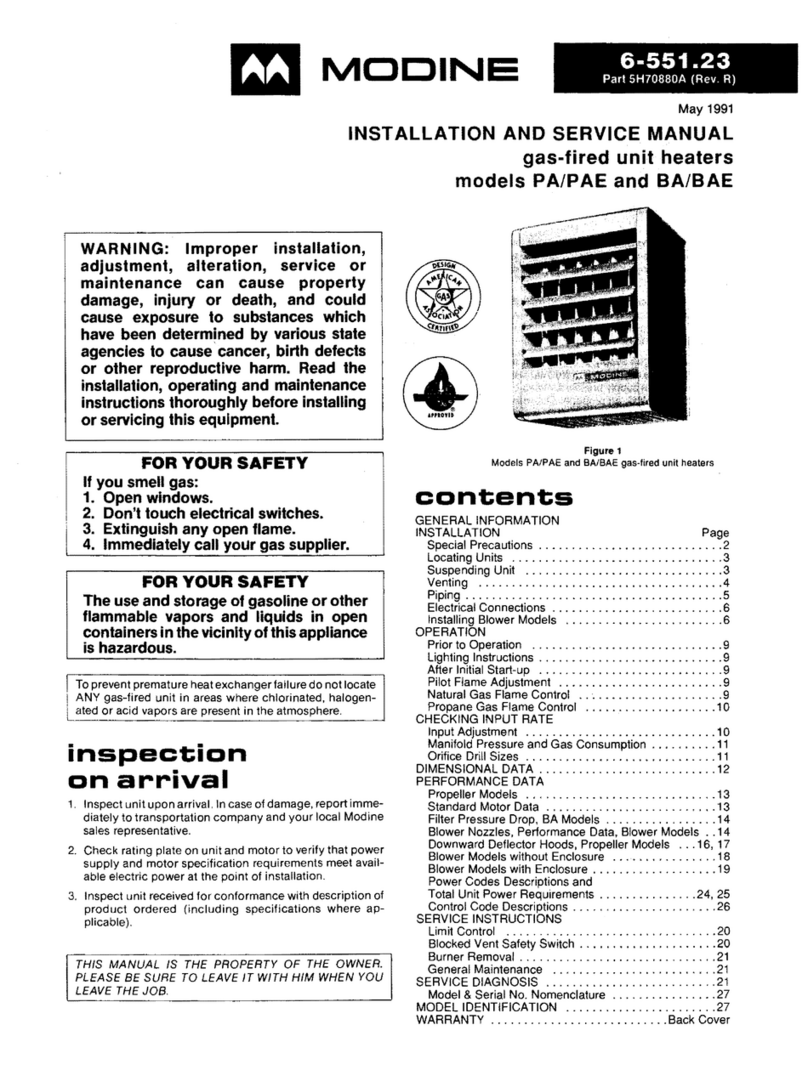
Modine Manufacturing VE Series Quick start guide

2-424.6
March, 2016
WIRING DIAGRAMS
Models HER, VE, PTE electric unit heaters
Two-In One Diagrams
Two wiring diagrams are furnished for each circuit configuration
in this manual. Included are a connection diagram at the left
for field installation and a circuit schematic at the right to aid in
continuity and trouble shooting.
Solid lines show pre-wiring performed at the factory; dotted
lines inform the installer of connections required to put the
heater in operation.
NOTE: As indicated in every diagram, all wiring must comply
with the National Electrical Code and all local codes. All
components must agree with their respective power source.
Wiring Diagram Selection
Diagrams are readily identified in the page location index on
the following page. This allows for the correct wiring diagram
to be selected using the model, size, and power code of the
unit heater.
Select the correct wiring diagrams as follows:
1. Determine unit heater model and size.
2. Select power code number from Table 2.3.
3. Reference unit heater model in the Page Location Index
(Table 2.4) with power code number of the corresponding
wiring diagram.
CAUTION
Turn off all power to unit before wiring. Failure to wire this unit
according to this wiring diagram may result in injury to the
installer or user. For deviations, contact factory.
Abbreviations and Symbols
To facilitate interpretation and enable simplification
the abbreviations and symbols have been selected as
recommended by ANSI (American National Standards
Institute) and NEMA (National Electrical Manufacturers
Association) standards.
XFMR or TR Transformer
VVolts
Hz Cycle or Hertz
φPhase
LC Limit Control
THERM or TH Thermostat
GGround
HTR Heater
HHot or High
SW Switch
CCommon
"J" Box Junction Box
LLow
H1, H2, etc. Transformer Primary Terminals
O.L.C. Overload Contact
RRelay
Rc Relay Contact
VA Volt-Ampere
X1,X2, etc. Transformer Secondary Terminals
L1, L2, etc. Electric Load Terminals
T1, T2, etc. Starter or Motor Terminals
Wire Color Coding
BK Black
BU Blue
RRed
WWhite
YYellow
Wire Color Coding
BK Black
BL Blue
RRed
WWhite
YYellow
X1,X2, etc. Transformer Secondary Terminals
L1, L2, etc. Electric Load Terminals
T1, T2, etc. Starter or Motor Terminals
2
Table 2.1
Unit Power Requirements (AMPS) - HER Models
Table 2.2
Unit Power Requirements (AMPS) - VE & PTE Models
2-424.5 — WIRING DIAGRAMS MODELS HER, VE, PTE
Table 2.3
Power Code Selection
Power Code 11 12 31 32 33
Power Supply (Volts/Phase)
208V/1 240V/1 208V/3 240V/3 480V/3
Table 2.4
Electric Unit Heater Page Location Index
Model No. Power Code
11 12 31 32 32
HER 30 3 3 5 5 8
HER 50 3 3 5 5 8
HER 75 3 3 5 5 8
HER100 4 4 5 5 8
HER125 - - 5 5 8
HER150 - - 6 5 8
HER200 - - 7 7 8
HER250 - - 7 7 8
VE 50 - 9 10 10 11
VE 75 - 9 10 10 11
VE100 - 9 10 10 11
VE150 - - 13 13 14
VE200 - - - 13 14
VE250 - - - - 14
VE300 - - - - 12
VE400 - - - - 12
VE500 - - - - 12
PTE300 - - - - 12
PTE400 - - - - 12
PTE500 - - - - 12
Power Supply HER 30 HER 50 HER 75 HER100 HER125 HER150 HER200 HER250
208/1 14.9 24.5 36.5 49.4 - - - -
240/1 12.9 21.3 31.7 42.9 - - - -
208/3 8.8 14.3 21.3 29.0 36.0 42.9 56.8 70.7
240/3 7.7 12.5 18.5 25.3 31.4 37.4 49.4 61.4
480/3 3.8 6.5 9.5 13.3 16.3 19.3 25.3 31.4
Power Supply VE50 VE75 VE100 VE150 VE200 VE200
VE/PTE300 VE/PTE400 VE/PTE500
1-stage 2-stage 1-stage 2-stage 1-stage 2-stage
208/1 - - - - - - - - - - - -
240/1 21.4 31.9 42.3 - - - - - - - - -
208/3 14.5 21.4 28.3 42.5 - - - - - - - -
240/3 12.7 18.6 24.6 37.0 49.0 - - - - - -
480/3 6.7 9.7 12.7 19.0 25.0 31.0 19.5 37.6 25.5 49.6 31.5 61.5
3
2-424.5 — WIRING DIAGRAMS MODELS HER, VE, PTE
POWER SUPPLY
208V OR 240V/60 Hz/1
Ø
LUG
GROUND
FUSED DISCONNECT
SWITCH (BY OTHERS)
CONTACTOR
HEATING ELEMENTS
LIMIT
CONTROL
THERM
MOTOR
FAN
COIL
5H70253A1 208V or 240V, single-phase power supply, 3kw, 5kw, 7.5kw Horizontal Models
4
2-424.5 — WIRING DIAGRAMS MODELS HER, VE, PTE
FUSEFUSE
POWER SUPPLY
208V OR 240V/60 Hz/1
Ø
LUG
GROUND
FUSED DISCONNECT
SWITCH (BY OTHERS)
CONTACTOR
HEATING ELEMENTS
LIMIT
CONTROL
THERM
MOTOR
FAN
COIL
5H70253A2 REV F 208V or 240V, single-phase power supply, 10kw Horizontal Model
5
2-424.5 — WIRING DIAGRAMS MODELS HER, VE, PTE
5H70253A4 REV E 208V or 240V, three-phase power supply, 3kw, 5kw, 7.5kw, 10kw, 12.5kw, 15kw Horizontal Models
15kw on 240V/3
only
Ø
POWER SUPPLY
LUG
GROUND
1
FUSED DISCONNECT
SWITCH (BY OTHERS)
CONTACTOR
HEATING ELEMENTS
LIMIT
CONTROL
THERM
MOTOR
FAN
COIL
208V OR 240V/60Hz/3
Ø
6
2-424.5 — WIRING DIAGRAMS MODELS HER, VE, PTE
Ø
208V/60Hz/3
COIL
FAN
MOTOR
THERM
CONTROL
LIMIT
HEATING ELEMENTS
CONTACTOR
SWITCH (BY OTHERS)
FUSED DISCONNECT
GROUND
LUG
POWER SUPPLY
FUSE FUSE
5H70253A5 208V, three-phase power supply, 15kw Horizontal Model
7
2-424.5 — WIRING DIAGRAMS MODELS HER, VE, PTE
Ø
208V OR 240V/60Hz/3
COIL
FAN
MOTOR
THERM
LIMIT
CONTROL
CONTACTOR
FUSED DISCONNECT
SWITCH (BY OTHERS)
GROUND
LUG
POWER SUPPLY
FUSE
FUSE
COIL
CONTACTOR
FUSE
FUSE FUSE
FUSE
HEATING ELEMENTS
HEATING ELEMENTS
5H70253A6 208V or 240V, three-phase power supply, 20kw, 25kw Horizontal Models
WARNING - HAZARDOUS VOLTAGE! IMPORTANT WIRING LEGEND
DISCONNECT POWER SUPPLY BEFORE MAKING CONNECTIONS.
ALL COMPONENTS MUST AGREE WITH THEIR RESPECTIVE
POWER SOURCE.
ALL UNITS MUST BE WIRED STRICTLY IN ACCORDANCE WITH
WIRING DIAGRAM FURNISHED WITH THE UNIT. ANY WIRING
DIFFERENT FROM THE WIRING DIAGRAM COULD RESULT IN A
HAZARD TO PERSONS AND PROPERTY. DAMAGE TO OR
FAILURE OF UNITS CAUSED BY INCORRECT WIRING IS NOT
COVERED BY STANDARD WARRANTY.
ANY ORIGINAL FACTORY WIRING THAT REQUIRES
REPLACEMENT MUST BE REPLACED WITH WIRING MATERIAL
HAVING A TERMPERATURE RATING OF AT LEAST 105ºF.
INSTALLATION OF WIRING MUST
CONFORM WITH LOCAL BUILDING
CODES OR IN THE ABSENCE OF LOCAL
CODES, OF THE ELECTRICAL CODE
ANSI/NFPA 70 - LATEST EDITION. UNIT
MUST BE ELECTRICALLY GROUNDED IN
CONFORMANCE TO THIS CODE.
IN CANADA, WIRING MUST COMPLY WITH
CSA C22.1, PART I , ELECTRICAL CODE -
LATEST EDITION.
FACTORY
INSTALLED
CONNECTED
PATH
FIELD
INSTALLED
COMPONENT
TERMINAL
BUS BAR
LIMIT
CONTROL
FAN
MOTOR
LINE VOLTAGE
THERMOSTAT
(MIN RATING
1
4HP @ 240V)
CONTROL
TERMINAL
BLOCK
L3
FUSED
DISCONNECT
SWITCH
(BY OTHERS)
L2
L1 GND
208V OR
240V/60Hz/3Ph
POWER SHOWN
POWER
TERMINAL
BLOCK
L3 T3
CONTACTOR 1
L1
L2
T1
T2
HEATING ELEMENTS
L3 T3
CONTACTOR 1
L1
L2
T1
T2
FUSE BLOCK
FUSE BLOCK
GROUND
LUG
HEATING ELEMENTS
8
2-424.5 — WIRING DIAGRAMS MODELS HER, VE, PTE
Ø
480V/60Hz/3
HEATING ELEMENTS
SWITCH (BY OTHERS)
FUSED DISCONNECT
480V
240V
FUSE
GROUND
LUG
POWER SUPPLY
FUSE
THERM
MOTOR
FAN
COIL
CONTROL
LIMIT
CONTACTOR
5H70253A7 480V or 600V, three-phase power supply, 3kw, 5kw thru 25kw Horizontal Models
9
2-424.5 — WIRING DIAGRAMS MODELS HER, VE, PTE
COIL
FAN
MOTOR
THERM
CONTROL
LIMIT
HEATING ELEMENTS
CONTACTOR
SWITCH (BY OTHERS)
FUSED DISCONNECT
GROUND
LUG
Ø
240V/60Hz/1
POWER SUPPLY
5H70253A8 240V, single-phase power supply, 5kw, 7.5kw, 10kw Vertical Models
10
2-424.5 — WIRING DIAGRAMS MODELS HER, VE, PTE
COIL
FAN
MOTOR
THERM
LIMIT
CONTROL
CONTACTOR
SWITCH (BY OTHERS)
FUSED DISCONNECT
GROUND
LUG
Ø
208V OR 240V/60Hz/3
POWER SUPPLY
HEATING ELEMENTS
5H70253A9 208V or 240V, three-phase power supply, 5kw, 7.5kw, 10kw Vertical Models
2-424.5 — WIRING DIAGRAMS MODELS HER, VE, PTE
Ø
480V/60Hz/3
POWER SUPPLY SHOWN
CONTACTOR
SWITCH (BY OTHERS)
FUSED DISCONNECT
GROUND
LUG
HEATING ELEMENTS
480V
240V
FUSE FUSE
THERM
FAN
MOTOR
COIL
LIMIT
CONTROL
11
5H70253A10 480V or 600V, three-phase power supply, 5kw, 7.5kw, 10kw Vertical Models
12
2-424.5 — WIRING DIAGRAMS MODELS HER, VE, PTE
480V/60Hz/3Ø
POWER SUPPLY SHOWN
LO
HI
FAN
MOTOR
LIMIT
CONTROL
COIL
CONTACTOR #1
2-STAGE
THERM
GROUND
LUG
480V
240V
FUSE FUSE
FUSE FUSE
FUSE
COIL
CONTACTOR #2
STAGE #1
HEATING ELEMENTS
FUSE FUSE
FUSE
HEATING ELEMENTS
STAGE #2
t°
t°
AUX.
SWITCH
L1 L2 L3
3Ø CIRCUIT BREAKER
(BY OTHERS)
5H70253A11 REV H 480V or 600V, three-phase power supply, 30kw, 40kw, and 50kw Vertical and Power Throw Models
2-424.5 — WIRING DIAGRAMS MODELS HER, VE, PTE
LIMIT
CONTROL
COIL
FAN
MOTOR
THERM
HEATING ELEMENTS
TIME DELAY RELAY
LUG
GROUND
FUSED DISCONNECT
SWITCH (BY OTHERS)
CONTACTOR
POWER SUPPLY SHOWN
208V or 240V/60Hz/3
Ø
13
5H70253A12 208V or 240-volt, three-phase power supply, 15kw, 20kw Vertical Models
14
2-424.5 — WIRING DIAGRAMS MODELS HER, VE, PTE
Ø
480V/60Hz/3
POWER SUPPLY SHOWN
CONTACTOR
SWITCH (BY OTHERS)
FUSED DISCONNECT
GROUND
LUG
HEATING ELEMENTS
480V
240V
FUSE FUSE
RELAY
DELAY
TIME
THERM
MOTOR
FAN
COIL
CONTROL
LIMIT
5H70253A13 480V or 600-volt, three-phase power supply, 15kw, 20kw, 25kw Vertical Models
15
THIS PAGE LEFT BLANK INTENTIONALLY
For SERVICE contact your local qualified installation and service contractor or appropriate utility company.
Modine Manufacturing Company • 1500 DeKoven Avenue • Racine, Wisconsin 53403-2552
Tel: 1.800.828.4328 (HEAT) • www.modine.com
© Modine Manufacturing Company 2016
As Modine Manufacturing Company has a continuous product improvement program, it reserves the right to change design and
specifications without notice.

This manual suits for next models

2

Other Modine Manufacturing Heater manuals
Modine Manufacturing HCH Series Manual

Modine Manufacturing

Modine Manufacturing HCH Series Manual

Modine Manufacturing POR Manual

Modine Manufacturing

Modine Manufacturing POR Manual

Modine Manufacturing PAE 30 Manual

Modine Manufacturing

Modine Manufacturing PAE 30 Manual

Modine Manufacturing PDE Manual

Modine Manufacturing

Modine Manufacturing PDE Manual

Modine Manufacturing BDP150 User manual

Modine Manufacturing

Modine Manufacturing BDP150 User manual

Modine Manufacturing IHR 60 Manual

Modine Manufacturing

Modine Manufacturing IHR 60 Manual

Modine Manufacturing Heatcraft 5WS1406C24.00 Technical Document
Modine Manufacturing

Modine Manufacturing Heatcraft 5WS1406C24.00 Technical Document

Modine Manufacturing AIR11-500.8 Manual

Modine Manufacturing

Modine Manufacturing AIR11-500.8 Manual

Modine Manufacturing HEX5 Series Quick start guide

Modine Manufacturing

Modine Manufacturing HEX5 Series Quick start guide

Modine Manufacturing Heatcraft Technical Document

Modine Manufacturing

Modine Manufacturing Heatcraft Technical Document

Modine Manufacturing PTX Manual

Modine Manufacturing

Modine Manufacturing PTX Manual

Modine Manufacturing IPT Manual

Modine Manufacturing

Modine Manufacturing IPT Manual

Modine Manufacturing HDS 30 Manual

Modine Manufacturing

Modine Manufacturing HDS 30 Manual

Modine Manufacturing MT28 Manual

Modine Manufacturing

Modine Manufacturing MT28 Manual

Modine Manufacturing MELMEL-24B1-120 Series Manual

Modine Manufacturing

Modine Manufacturing MELMEL-24B1-120 Series Manual

Modine Manufacturing PTC Manual

Modine Manufacturing

Modine Manufacturing PTC Manual

Modine Manufacturing POR oil-fired unit User manual

Modine Manufacturing

Modine Manufacturing POR oil-fired unit User manual

Modine Manufacturing HD User manual

Modine Manufacturing

Modine Manufacturing HD User manual

Modine Manufacturing IPT Series Manual

Modine Manufacturing

Modine Manufacturing IPT Series Manual

Modine Manufacturing PTS Manual

Modine Manufacturing

Modine Manufacturing PTS Manual

Modine Manufacturing LM Manual

Modine Manufacturing

Modine Manufacturing LM Manual

Modine Manufacturing PV Series Manual

Modine Manufacturing

Modine Manufacturing PV Series Manual

Modine Manufacturing HD100 User manual
Modine Manufacturing

Modine Manufacturing HD100 User manual

Modine Manufacturing AMP Manual

Modine Manufacturing

Modine Manufacturing AMP Manual
Popular Heater manuals by other brands

Honeywell HZ-850 Series instructions

Honeywell

Honeywell HZ-850 Series instructions

L.B. White Foreman owner's manual

L.B. White

L.B. White Foreman owner's manual

THERMOBILE BX 3 user manual

THERMOBILE

THERMOBILE BX 3 user manual

Jaga LOW-H20 Energy Savers Installation

Jaga

Jaga LOW-H20 Energy Savers Installation

Timberk TFH S20SMA instruction manual

Timberk

Timberk TFH S20SMA instruction manual

Consort Frost Fighter instructions

Consort

Consort Frost Fighter instructions

SIC CFR Series Installation, use & maintenance manual

SIC

SIC CFR Series Installation, use & maintenance manual

Nibe EAH 10 Installer manual

Nibe

Nibe EAH 10 Installer manual

Trotec TAC XT 18 Original instructions

Trotec

Trotec TAC XT 18 Original instructions

Remington HH-18-PCH-A User's manual & operating instructions

Remington

Remington HH-18-PCH-A User's manual & operating instructions

Lasko CC23150 operating manual

Lasko

Lasko CC23150 operating manual

Videotec ODBH18K1 instruction manual

Videotec

Videotec ODBH18K1 instruction manual

Rowi HIH 2000/ 1/1 operating instructions

Rowi

Rowi HIH 2000/ 1/1 operating instructions

Berko BDBSL Installation, operation & maintenance instructions

Berko

Berko BDBSL Installation, operation & maintenance instructions

EmaHome IPW-425 instruction manual

EmaHome

EmaHome IPW-425 instruction manual

Leister LE 5000 DF operating instructions

Leister

Leister LE 5000 DF operating instructions

Sapir SP-1970-F instruction manual

Sapir

Sapir SP-1970-F instruction manual

Rittal SK 3215.100 Assembly instructions

Rittal

Rittal SK 3215.100 Assembly instructions

manuals.online logo
manuals.online logoBrands
  • About & Mission
  • Contact us
  • Privacy Policy
  • Terms and Conditions

Copyright 2025 Manuals.Online. All Rights Reserved.