7/8
07/01 AWA8230-1935
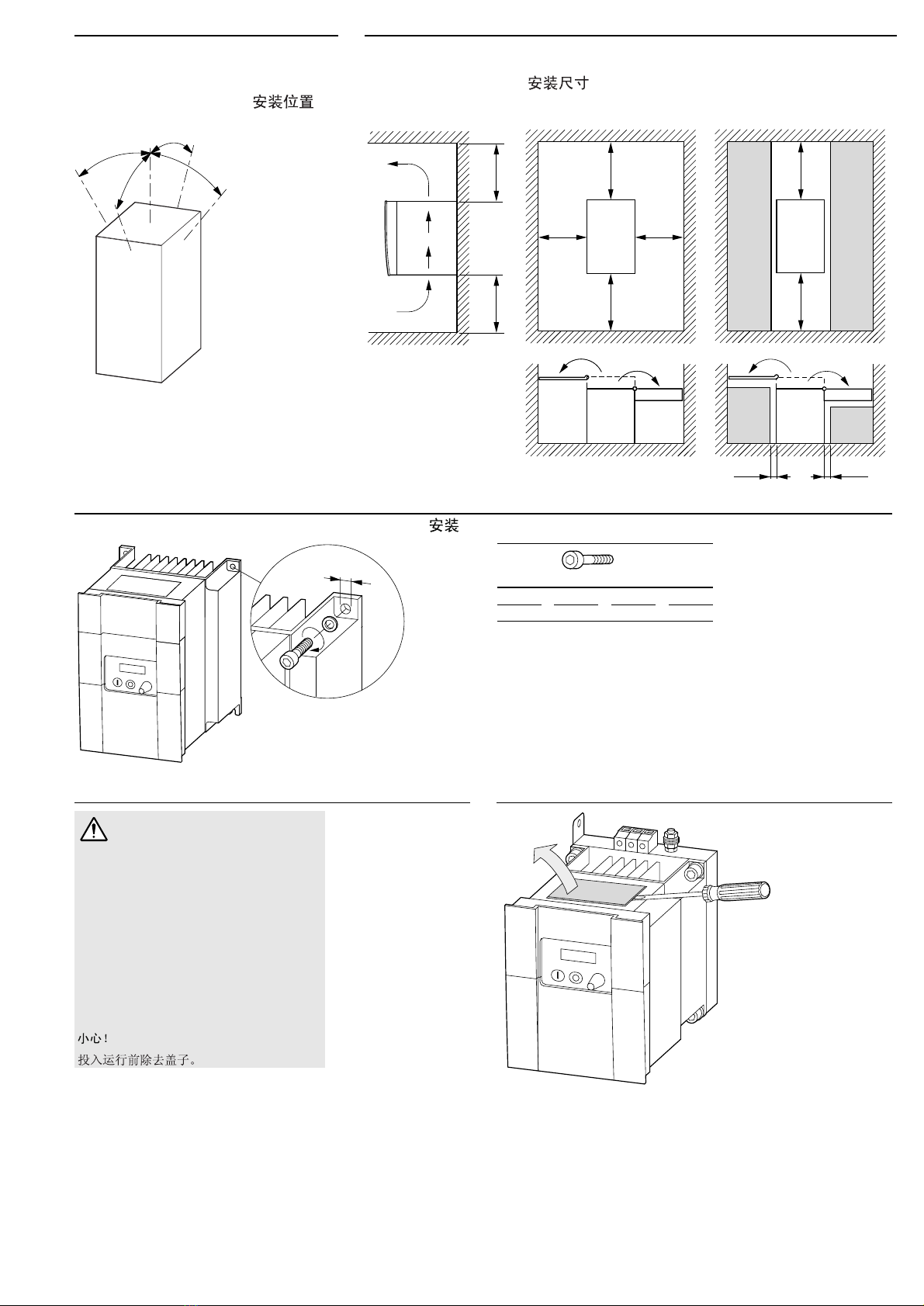
Vorsicht!
Im Geltungsbereich der EG-Richtlinien dürfen die Frequenzumrichter und
deren Zubehör nur dann in Betrieb genommen werden, wenn festgestellt
wird, dass die Maschine die Schutzanforderungen der Maschinenrichtlinie
89/392/EWG erfüllt.
¡Atención!
En el campo de aplicación de la normativa CE, los convertidores de frecuencia y
sus correspondientes accesorios sólo deberán ponerse en marcha cuando se asegure
que la máquina cumple con las exigencias de seguridad de la normativa de máquinas
89/392/CE.
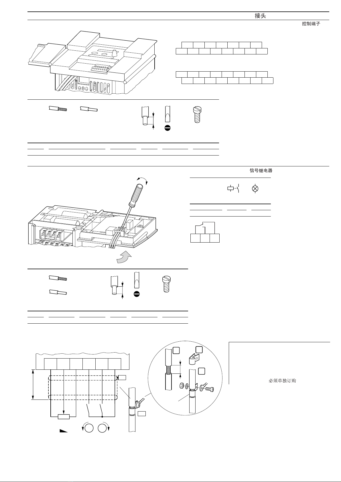
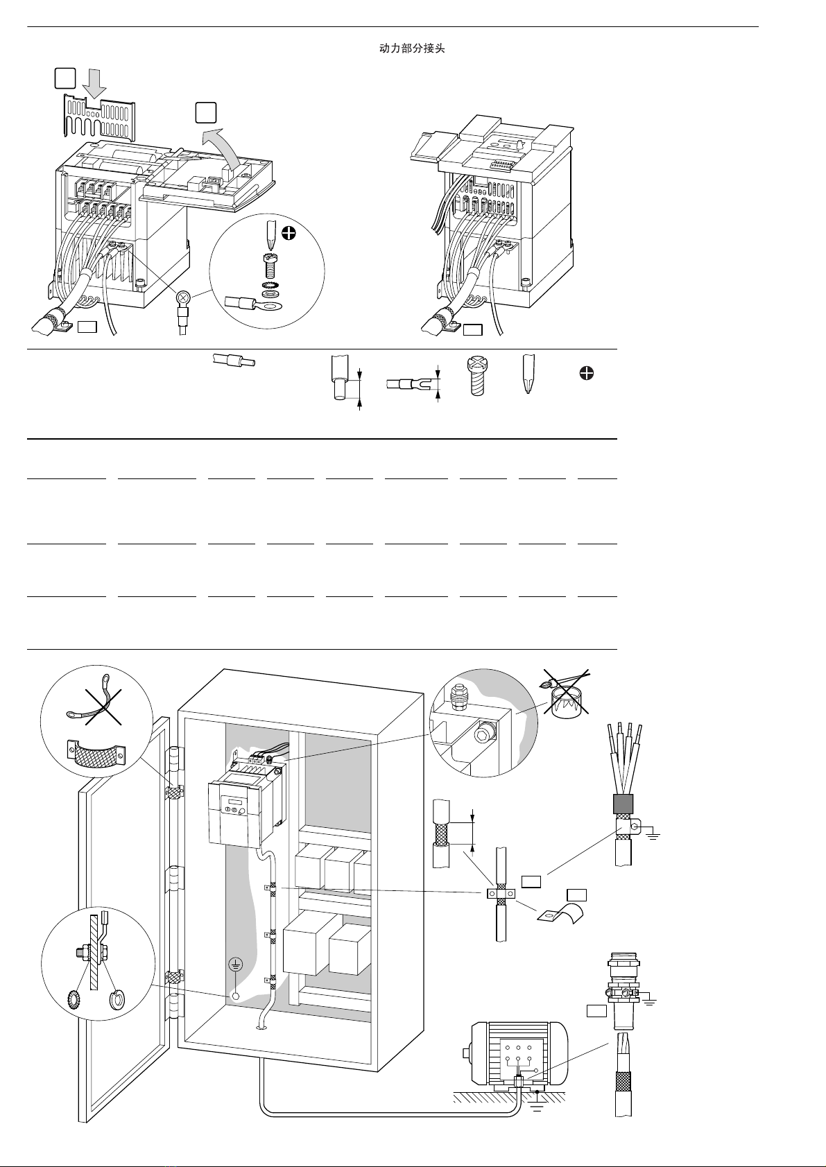
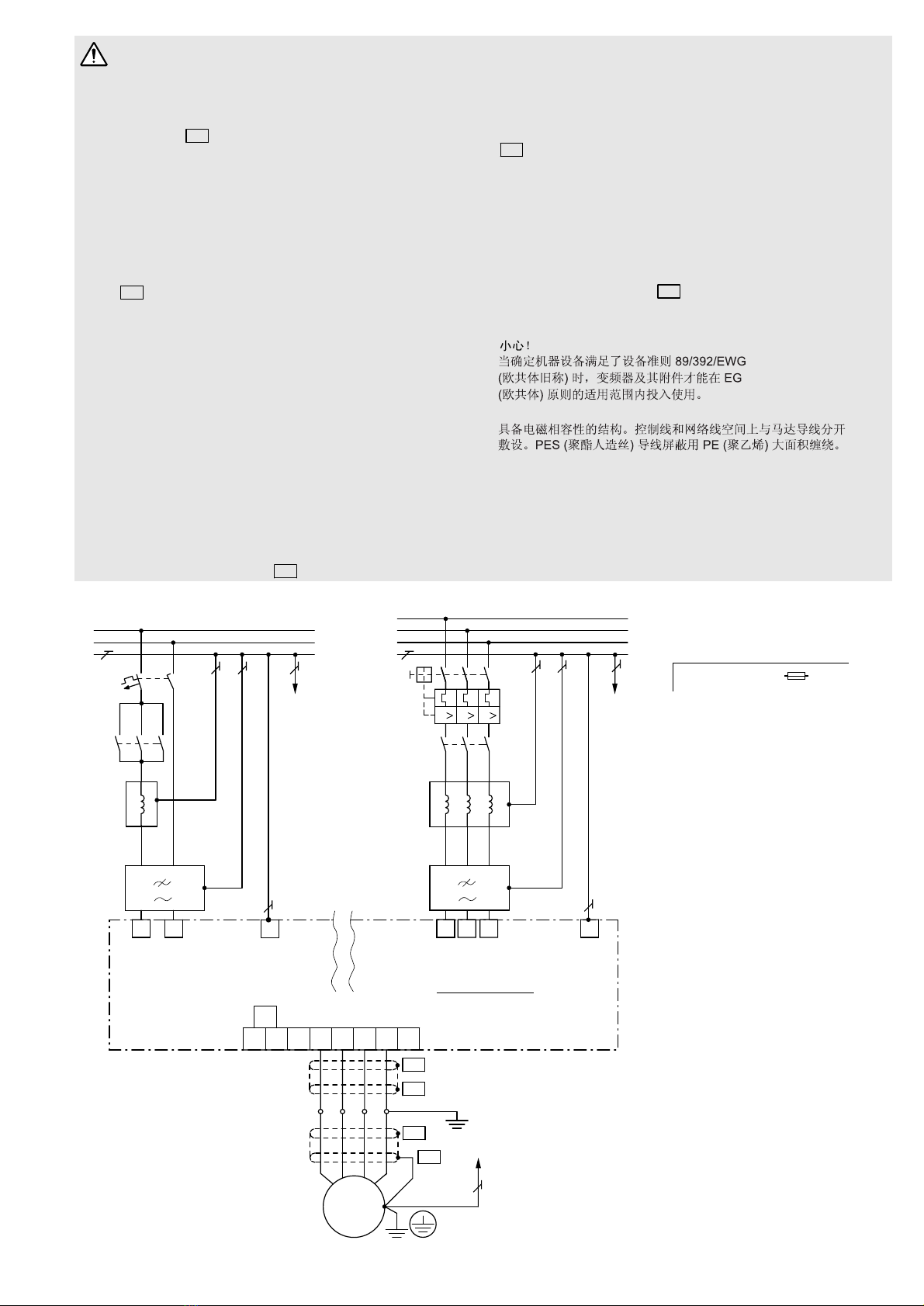
EMV-gerechter Aufbau. Steuer- und Netzleitungen räumlich getrennt von der
Motorleitung verlegen. Leitungsschirm großflächig mit PE verbinden. El montaje debe cumplir CEM. Los cables de mando y de conexión a red se deben
instalar independientemente del cable de conexión al motor. El cable apantallado
se debe conectar a masa utilizando una amplia superficie de contacto.
Caution!
Within the scope of the EU Directives, the frequency inverters and their accessories
may be commissioned only provided it is established that the machine fulfils the
protective requirements of Machine Directive 89/392/EWG.
Осторожно!
На территории действия Предписаний ЕС преобразователя частоты и его
принадлежности можно вводить в эксплуатацию только в том случае, если
будет установлено, что машина выполняет требования по защите согласно
Предписанию для машин 89/392/ЕЭС.
Ensure EMC-compliant installation. Lay control and communication cables spatially
separated from the motor cable. Ensure a large contact area connection
between cable screen and PE.
Сборка соответственно электромагнитной совместимости. Линии
управления и электросети прокладывать в пространственном отношении
отдельно от линии двигателя. cиловой экран соединять с PE по
большой площади.
Attention !
En application des directives européennes, les convertisseurs de fréquence et leurs
accessoires ne doivent être mis en service que s’il a été vérifié que la machine répond
bien aux exigences de la directive machines 89/392/EWG.
Montage conforme aux règles de la CEM. Eloigner les câbles de commande et de
réseau des câbles puissance. Relier le blindage au PE en assurant de grandes surfaces
de contact.
Attenzione!
Nel campo di validità delle direttive CEE i convertitori di frequenza e i loro accessori
possono essere messi in esercizio solamente se è verificato che la macchina soddisfa
i requisiti di sicurezza delle direttive macchine 89/392/CEE.
Montaggio secondo CEM. Disporre i cavi comandi e di alimentazione separati dal cavo
del motore. Collegare lo schermo del cavo con PE con un’ampia superficie.
PES PES
PES PES
PES
PE
L
N
PE
2
LN
1
L1
PE
PE
DF5-322...
DV5-322...
1 h230 V, 50/60 Hz
DF5-322...
DV5-322...
3 h230 V, 50/60 Hz
DF5-340...
DV5-340...
3 h400 V, 50/60 Hz
L
Z1
G1
N
W2
L1 L2 L3 PE
L1
L2
L3
PE
K1M
Q1
V2U2
L1 L2 L3
W1V1U1
L1
Z1
PE
PE
K1M
DC+
DC–
L+ UVWPE BR
PES
PES
PE
PES
PES
M
M1
X1
3 ~
PE PE
III
F1 hF1, Q1 =